Note: Descriptions are shown in the official language in which they were submitted.
CA 02344777 2001-04-24
Area Designing Apparatus and Method for Mobile Communication System
Background of the Invention
Field of the Invention:
The present invention relates to an area designing apparatus and
method for a mobile communication system, the area designing apparatus
having a means for calculating a transmission power of a signal transmitted
between a base station and each of a plurality of mobile station.
Description of the Prior Art:
A mobile communication system provides a communication service
l0 using a plurality of base stations disposed in the service area thereof. To
improve the quality of the communication service, the mobile
communication system has an area designing apparatus. The area
designing apparatus evaluates the communication quality of a signal
transmitted between each of a plurality of mobile stations and one of the
base stations. Corresponding to the evaluated result, the communication
service provider increases the number of base stations and changes designed
radio parameters.
The area designing apparatus randomly places a plurality of
communicating mobile stations in a radio zone of a specified base station
corresponding to traffic distribution information so as to designate the base
station that is radio linked to each of the mobile stations. The area
designing apparatus calculates the transmission power of a signal
1
CA 02344777 2001-04-24
transmitted between the base station and each of mobile stations that are
radio linked thereto and evaluates the communication quality of a signal
transmitted between the base station and each of the plurality of mobile
stations corresponding to the calculated result.
To consider the case that a signal that a specified mobile station
transmits interferes with a signal that another mobile station transmits, a
plurality of mobile stations are placed. In addition, since the transmission
power of a signal transmitted between the base station and each mobile
station varies depending on the position of each mobile station, the mobile
l0 stations are placed corresponding to traffic distribution information.
Thus,
the communication quality of the communication service is evaluated in
consideration of the traffic distribution.
Fig. 1 is a schematic diagram for explaining the theory of the
evaluation of the communication quality of a signal transmitted between
each of a plurality of mobile stations and a base station, the evaluation
being performed by an area designing apparatus of a conventional mobile
communication system. Fig. 1 shows base stations 1 and 2 disposed in the
service area of the communication service provider. The base stations 1
and 2 have radio zones 1a and lb, respectively. Mobile stations 21 to 23
are placed in the radio zone la. In reality, there are other base stations
and mobile stations along with the base stations 1 and 2 and the mobile
stations 21 to 23 shown in Fig. 1.
2
CA 02344777 2001-04-24
It is assumed that the mobile communication system uses code
division multiple access system (CDMA) that uses one frequency band for
each of the up link line and the down link line.
When each of the mobile stations 21 to 23 is in communication and
radio linked to the base station 1, the area designing apparatus calculates
the transmission power of a signal transmitted from the base station 1 to
each of the base stations 21 to 23 and the transmission power of a signal
transmitted from each of the mobile stations 21 to 23 to the base station 1.
In addition, corresponding to the calculated result, the area designing
l0 apparatus calculates the desired wave power of each desired wave signal
and the interference wave power of each interference wave signal
transmitted between each of the mobile stations 21 to 23 and the base
station 1 and obtains (each desired wave power / each interference wave
power). The communication quality is proportional to (each desired wave
power / each interference wave power). For example, when the ratio of
mobile stations that do not satisfy a predetermined threshold value of (each
desired wave power / each interference wave power) is large, the
communication provider disposes a new base station and changes the
designed radio parameters so as to improve the communication quality.
In this case, to obtain the desired wave power and the interference
wave power, the area designing apparatus designates the transmission
power of a signal transmitted through each radio line to an constant initial
3
CA 02344777 2001-04-24
value. In that state, the area designing apparatus randomly and
successively selects each radio line and changes the transmission power
thereof so that the communication quality of a signal transmitted through
the selected radio line satisfies a predetermined target value while the
transmission power does not deviate from the range of the predetermined
maximum transmission power and the predetermined minimum
transmission power. After the area designing apparatus have selected all
the radio lines and changed the transmission powers thereof, since a change
of the transmission power of a specified radio line causes the interference
l0 wave powers of the other radio lines, the communication qualities of the
radio lines other than the last selected radio line may deviate from the
desired target value even if the transmission powers do not deviate from the
range of the maximum transmission power and the minimum transmission
power.
For a radio line that has been earlier selected, even if the
transmission power of the radio line is in the range between the maximum
transmission power and the minimum transmission power, the difference
between the communication quality and the predetermined target tends to
become large. Thus, to decrease the difference, each radio line is
repeatedly selected and the transmission power thereof is repeatedly
increased and decreased so as to converge the transmission power and
evaluate the communication quality. Thus, the mobile communication
4
CA 02344777 2001-04-24
system using the code division multiple access method should evaluate the
communication quality in such a manner.
In addition, the communication quality of each mobile station placed
in an area with a predetermined size is evaluated. As a result, the
deterioration ratio which is a ratio of mobile stations that do not satisfy a
predetermined level is obtained. The communication qualities at positions
of a plurality of mobile stations and the deterioration ratios in a plurality
of
areas are displayed in colors as visual information on a map.
However, the communication qualities of mobile stations can be
l0 evaluated only at random positions thereof corresponding to traffic
distribution information. The number of positions at which communication
qualities can be evaluated is less in an area where the traffic density is low
than another area where the traffic density is high. In addition, the
positions at which the traffic qualities are evaluated are randomly
designated. Thus, it is desired to improve the area designing apparatus so
as to evaluate communication qualities at positions designated at any
constant intervals regardless of the traffic density. In addition, the same
number of evaluation results of communication qualities is required in each
area in order that the communication quality of each mobile station is
evaluated in each area having a predetermined size and the ratio of mobile
stations that do not satisfy a predetermined level of communication
qualities is obtained. However, since the mobile stations are placed at
5
CA 02344777 2004-08-04
74935-33
random corresponding to the traffic distribution
information, the number of evaluation results of the
communication qualities obtained in the individual areas
fluctuates. Thus, the statistical reliability of the
deterioration ratio calculated in each area varies
corresponding to the traffic density.
Summary of the Invention
Therefore, an object of the present invention is
to provide an area-designing apparatus that is used for a
mobile communication system and that allows communication
qualities at positions designated at any equal intervals to
be evaluated regardless of a traffic density. In addition,
another object of the present invention is to provide an
area-designing apparatus that is used for a mobile
communication system and that allows a deterioration ratio
to be obtained with a constant statistic reliability in each
area with any size.
According to a broad aspect, the invention
provides an area-designing apparatus having processing means
for simulating a CDMA mobile communication system, the
processing means comprising: means for placing on a map a
plurality of communicating mobile stations corresponding to
traffic distribution information; means for assigning, for
each mobile station, a base station to which the mobile
station is radio-linked; means for calculating transmission
power of a signal that each base station transmits to each
of the mobile stations that are radio-linked thereto so that
a ratio of reception power of a signal to reception power of
interferences converges to a predetermined value, said
reception power of a signal being that of a signal that each
mobile station receives from the base station radio-linked
thereto, said reception power of interferences being that of
6
CA 02344777 2004-08-04
74935-33
interferences that the same mobile station receives from the
base station radio-linked thereto and from each of the other
base stations, converges to a predetermined value; means for
successively selecting, while each base station is
transmitting the calculated transmission power signal, each
of a plurality of evaluation positions on the map which are
independent from positions at which the mobile stations are
placed on the map; and, means for calculating reception
power of a signal received by an additional evaluation
mobile station placed on the map at each selected evaluation
position, the signal being received from the base station
that the additional evaluation mobile station is radio-
linked thereto, and for calculating reception power of
interferences received by the additional evaluation mobile
station from all of the base stations including the base
station to which the additional evaluation mobile station is
radio-linked; wherein communication quality at each
evaluation position is evaluated corresponding to the
calculated reception signal power and the calculated
reception power of the interferences.
According to another broad aspect, the invention
provides an area-designing apparatus having processing means
for simulating a CDMA mobile communication system, the
processing means comprising: means for placing on a map a
plurality of communicating mobile stations so as to
correspond to traffic distribution information, the
apparatus comprising: means for assigning, for each mobile
station, a base station to which the mobile station is
radio-linked; means for calculating transmission power of a
signal that each mobile station transmits to the base
station that is radio-linked thereto so that a ratio of a
reception power of a signal to reception power of
interferences converges to a predetermined value, said
6a
CA 02344777 2004-08-04
74935-33
reception power of a signal being that of a signal that each
base station receives from each mobile station radio-linked
thereto, said reception power of interferences being that of
interferences that the same base station receives from the
other mobile stations; means for successively selecting,
while each mobile station is transmitting the calculated
transmission power signal, each of a plurality of evaluation
positions on the map which are independent from positions at
which the mobile stations are placed on the map; and, means
for calculating reception power of a signal received by the
base station from an additional evaluation mobile station
placed on the map at each selected evaluation position, the
signal being received from the additional evaluation mobile
station that the base station is radio-linked thereto, and
for calculating reception power of interferences that the
base station receives from mobile stations other than the
additional evaluation mobile station; wherein communication
quality at each evaluation position is evaluated
corresponding to the calculated reception signal power and
the calculated reception power of the interferences.
According to a further broad aspect, the invention
provides an area-designing method for simulating a CDMA
mobile communication system, comprising steps of: placing a
plurality of communicating mobile stations on a map so as to
correspond to traffic distribution information; assigning,
for each mobile station, a base station to which the mobile
station is radio-linked; calculating transmission power of a
signal that each base station transmits to each of the
mobile stations that are radio-linked thereto so that a
ratio of reception power to reception power of interferences
converges to a predetermined value, said reception power of
a signal being that of a signal that each mobile station
receives from the base station radio-linked thereto, said
6b
CA 02344777 2004-08-04
74935-33
reception power of interferences being that of interferences
that the same mobile station receives from the base station
radio-linked thereto and from each of the other base
stations; successively selecting, while each base station is
transmitting the calculated transmission power signal, each
of a plurality of evaluation positions on the map which are
independent from positions at which the mobile stations have
been placed on the map; and, calculating a reception power
of a signal received by an additional evaluation mobile
station placed at each selected evaluation position, the
signal being received from the base station that the
additional evaluation mobile station is radio-linked
thereto, and calculating reception power of interferences
received by the additional evaluation mobile station from
all of the base stations including the base station to which
the additional evaluation mobile station is radio-linked;
wherein communication quality at each evaluation position is
evaluated corresponding to the calculated reception signal
power and the calculated reception power of the
interferences.
According to a further broad aspect, the invention
provides an area-designing method for a CDMA simulating
mobile communication system, comprising steps of: placing a
plurality of communicating mobile stations on a map so as to
correspond to traffic distribution information; assigning,
for each mobile station, a base station to which the mobile
station is radio-linked; calculating transmission power of a
signal that each mobile station transmits to the base
station that is radio-linked thereto so that a ratio of
reception power of a signal to reception power of
interferences converges to predetermined value, said
reception power of a signal being that of a signal that each
base station receives from each mobile station radio-linked
6c
CA 02344777 2004-08-04
74935-33
thereto, said reception power of interferences being that of
interferences that the same base station receives from the
other mobile stations; successively selecting, while each
mobile station is transmitting the calculated transmission
power signal, each of a plurality of evaluation positions on
a map which are independent from positions at which the
mobile stations have been placed on the map; and,
calculating reception power of a signal received by the base
station from an additional evaluation mobile station placed
at each selected evaluation position, the signal being
received from the additional evaluation mobile station that
the base station is linked thereto, and calculating
reception power of interferences that the base station
receives from mobile stations other than the additional
evaluation mobile station; wherein communication quality at
each evaluation position is evaluated corresponding to the
calculated reception signal power and the calculated
reception power of the interferences.
According to a first aspect of the present
invention, there is provided an area-designing apparatus for
a mobile communication system, comprising: means for
placing a plurality of communicating mobile stations
corresponding to traffic distribution information; means for
deciding a base station to which each of the mobile stations
is radio-linked; means for calculating a transmission power
of a desired wave signal that each base station transmits to
each of the mobile stations that are radio-linked thereto;
means for successively selecting one from a plurality of
evaluation positions in a state that each of the base
stations is transmitting the desired
6d
CA 02344777 2001-04-24
wave signals and means for calculating a reception power of a desired wave
signal that an evaluation mobile station placed at each selected evaluation
position receives from the base station that is radio linked thereto and
reception powers of interference wave signals that the evaluation mobile
station receives from the base station that is radio linked thereto and from
each of the other base stations, wherein communication quality at each
evaluation position is evaluated corresponding to the calculated reception
power of the desired wave signal and the calculated reception powers of the
interference wave signals.
l0 According to a second aspect of the present invention, there is
provided an area designing apparatus for a mobile communication system,
comprising: means for placing a plurality of communicating mobile stations
corresponding to traffic distribution information means for deciding a base
station to which each of the mobile stations is radio linked means for
calculating a transmission power of a desired wave signal that each of the
mobile stations transmits to the base station that is radio linked thereto
means for successively selecting one from a plurality of evaluation positions
in a state that each of the plurality of mobile stations is transmitting the
desired wave signal means for calculating a reception power of a desired
wave signal that the base station that is radio linked to an evaluation
mobile station placed at each selected evaluation position receives from the
evaluation mobile station and reception powers of interference wave signals
7
CA 02344777 2001-04-24
that the base station that is radio linked to the evaluation mobile station
receives from the mobile stations other than the evaluation mobile station,
wherein the communication quality at the evaluation position is evaluated
corresponding to the calculated reception power of the desired wave signal
and the calculated reception powers of the interference wave signals.
In the area designing apparatus according to the first or second
aspect, a random deviation amount may be added to a propagation loss of a
signal transmitted between the evaluation mobile station placed at each
evaluation position and each base station, and corresponding to the
l0 resultant propagation loss, the reception power of the desired wave signal
and the reception powers of the interference wave signals may be calculated
so as to evaluate the communication quality at each evaluation position,
and the evaluation of the communication quality may be repeated and the
ratio that represents the number of evaluation results that do not satisfy a
predetermined level is obtained.
In the area designing apparatus according to the first or second
aspect, the communication quality at each evaluation position in an area
that contains some of the plurality of evaluation positions may be evaluated,
and a ratio that represents the number of evaluation results at the
evaluation positions in the area do not satisfy a predetermined level may be
obtained.
In the area designing apparatus according to the first or second
8
CA 02344777 2001-04-24
aspect, the evaluation positions may be decided so that some of the plurality
of evaluation positions are formed in a regular polygon shape.
The area designing apparatus according to the first or second aspect
may comprise: means for displaying the communication quality at each
evaluation position with visual information.
The area designing apparatus according to the first or second aspect
may comprise: means for displaying the ratio that represents evaluation
results that do not satisfy a predetermined level with the visual information.
The area designing apparatus according to the first or second aspect
l0 may comprise: means for inputting the traffic distribution information
means for storing the input traffic distribution information and means for
outputting the visual information.
These and other objects, features and advantages of the present
invention will become more apparent in light of the following detailed
description of the best mode embodiment thereof, as illustrated in the
accompanying drawings.
Brief Description of Drawings
Fig. 1 is a schematic diagram for explaining the theory of the
evaluation of a communication quality of a signal transmitted between each
of a plurality of mobile stations and a base station, the evaluation being
performed by an area designing apparatus used in a conventional mobile
communication system
9
CA 02344777 2001-04-24
Fig. 2 is a block diagram showing the structure of an area designing
apparatus according to a first embodiment of the present invention
Fig. 3 is a schematic diagram for explaining the theory of the
evaluation of the communication quality of a signal transmitted between
each of a plurality of mobile stations and a base station, the evaluation
being performed by an area designing apparatus shown in Fig. 2~
Fig. 4 is a flow chart showing the operation of the area designing
apparatus shown in Fig. 2~
Fig. 5 is a flow chart showing the operation of the area designing
apparatus shown in Fig. 2~ and
Fig. 6 is a flow chart showing the operation of an area designing
apparatus according to a second embodiment of the present invention.
Description of Preferred Embodiments
(The first embodiment)
Fig. 2 is a block diagram showing the structure of an area designing
apparatus for a mobile communication system according to the first
embodiment of the present invention. The area designing apparatus shown
in Fig. 2 comprises an inputting portion 101, a storing portion 104, a
processing portion 102, and an outputting portion 103. The inputting
portion 101 inputs information such as traffic occurrence range information,
map information, traffic distribution information, evaluation position
information, base station position information, and radio parameter
l0
CA 02344777 2001-04-24
information. The storing portion 104 stores each information that is input.
The processing portion 102 obtains the reception quality at the evaluation
position corresponding to each information stored in the storing portion 104.
The outputting portion 103 outputs the obtained reception quality.
The processing portion 102 comprises a mobile station placer 121, a
propagation loss calculator 122, and a linking base station decider123. The
mobile station placer 121 randomly places a plurality of communicating
mobile stations on for example a real map corresponding to input traffic
distribution information. The propagation loss calculator 122 selects a
l0 specified mobile station from the plurality of mobile stations placed on
the
map and calculates the propagation loss of a signal transmitted between the
selected mobile station and the base station corresponding to the input map
information. The linking base station decider 123 decides a base station
that is radio linked to each of a plurality of mobile stations corresponding
to
the calculated propagation loss.
The processing portion 102 further comprises a base station
transmission power calculator 124 and a mobile station transmission power
calculator 125. The base station transmission power calculator 124
calculates the transmission power of a signal that the base station
transmits to each of the plurality of mobile stations that is radio linked
thereto corresponding to the position and propagation loss of each of the
plurality of mobile stations. The mobile station transmission power
11
CA 02344777 2001-04-24
calculator 125 calculates the transmission power of a signal that each of the
plurality of mobile stations transmits to the base station that is radio
linked
thereto corresponding to the position and propagation loss of each of the
plurality of mobile stations.
The processing portion 102 further comprises a down link line power
ratio calculator 126, an up link line power ratio calculator 127, and a
controller 120. The down link line power ratio calculator 126 calculates
(desired wave power / interference wave power) of a signal of a down link
line that is received by a communicating mobile station that is placed at any
l0 evaluation position. The up link line power ratio calculator 127 calculates
(desired wave power / interference wave power) of a signal of an up link line
that a base station receives from a mobile station that is placed at any
evaluation position and that is radio linked thereto. The controller 120
controls the operation of the processing portion 102.
The traffic occurrence range information is information about the
range in which a traffic occurs on a real map. The map information is
altitude data of a land. The traffic distribution information is information
about a traffic amount that occurs per unit size of each specified area. The
evaluation position information is information about a plurality of
evaluation positions designated for obtaining communication qualities.
The base station position information is information that represents
the position of each of a plurality of base stations placed on a real map.
12
CA 02344777 2001-04-24
The radio parameter information is information such as the antenna gain of
an antenna disposed in each of the plurality of base stations, the maximum
value of the transmission powers of the down link lines, and the maximum
value of the transmission powers of the up link lines.
According to the first embodiment of the present invention, each of
intersections of a plurality of lines at intervals of 100 meters in the south -
north direction and a plurality of lines at intervals of 100 meters in the
east
- west direction are designated as evaluation positions on the map.
Alternatively, evaluation positions may be placed so that some of them form
l0 regular polygons in for example a honeycomb shape or delta shape. The
evaluation position information that is input through the inputting portion
101 can be freely changed by the user of the area designing apparatus such
as the communication service provider.
Next, according to the first embodiment of the present invention, a
method for evaluating the communication quality for a mobile
communication system using the code division multiple access (CDMA),
which uses one frequency band for each of an up link line and a down link
line, will be described.
Fig. 3 is a schematic diagram for explaining the theory of the
evaluation of the communication quality of a signal transmitted between
each of a plurality of mobile stations and a base station, the evaluation
being performed by the area designing apparatus shown in Fig. 2. Fig. 3
13
CA 02344777 2001-04-24
shows base stations 1 and 2 and mobile stations 21 and 22. The mobile
stations 21 and 22 are placed in a radio zone la of the base station 1. In
Fig. 3, reference numeral lb represents a radio zone of the base station 2.
The intersections of broken lines drawn in the east - west direction and the
south - north direction represent evaluation positions. In reality, there are
a plurality of base stations and mobile stations as well as the base stations
1 and 2 and the mobile stations 21 and 22 shown in Fig. 3.
In this example, the transmission power of a signal transmitted from
the base station 1 to the mobile station 21 is denoted by Pba. The
l0 transmission power of a signal transmitted from the mobile station 21 to
the
base station 1 is denoted by Pma. The transmission power of a signal
transmitted from the base station 1 to the mobile station 22 is denoted by
Pbb. The transmission power of a signal transmitted from the mobile
station 22 to the base station 1 is denoted by Pmb.
In this case, it is assumed that the reception power of a signal that
each of the mobile stations 21 and 22 receives from the base station 1 is less
than each of Pba and Pbb and that the propagation loss thereof varies
corresponding to the distance between each of the mobile stations 21 and 22
and the base station 1, the position of each of the mobile stations 21 and 22,
and so forth. In this example, the propagation loss between the base
station 1 and the mobile station 21 is denoted by Lal. The propagation
loss between the base station 1 and the mobile station 22 is denoted by Lb 1.
14
CA 02344777 2001-04-24
The propagation loss between the base station 2 and the mobile station 21
is denoted by La2. The propagation loss between the base station 2 and
the mobile station 22 is denoted by Lb2.
When the mobile stations 21 and 22 are in communication and they
are radio linked to the base station 1, the area designing apparatus
according to the first embodiment calculates the transmission power of a
signal transmitted from the base station 1 to each of the mobile stations 21
and 22 and the transmission power transmitted from each of the mobile
stations 21 and 22 to the base station 1.
l0 The area designing apparatus successively selects an evaluation
position, calculates the desired wave power and the interference wave power
of signals transmitted through each of an up link line and a down link line
of each mobile station at the selected evaluation position, and obtains (each
desired wave power / each interference wave power). In this case, the
calculated results of the transmission powers of signals transmitted
between the base station 1 and each of the mobile stations 21 and 22 are
used. The communication quality is proportional to (each desired wave
power / each interference wave power). When the ratio of evaluation
positions at which a predetermined threshold value of (each desired wave
power / each interference wave power) is not satisfied is large, the
communication provider disposes a new base station and changes designed
radio parameters so as to improve the communication quality.
CA 02344777 2001-04-24
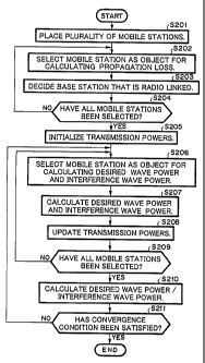
Figs. 4 and 5 are flow charts showing the operation of the area
designing apparatus shown in Fig. 2. First of all, traffic occurrence range
information, map information, traffic distribution information, evaluation
position information, base station evaluation position information, radio
parameter information, and so forth are input through the inputting portion
101, output to the storing portion 104, and temporarily stored to the storing
portion 104.
In response to an instruction supplied from the controller 120, the
mobile station placer 121 randomly places the plurality of mobile stations
l0 21 and 22 on a map as shown in Fig. 3 corresponding to traffic distribution
information stored in the storing portion 104 (at step 5201).
Thereafter, the controller 120 selects a mobile station as an object to
calculate a propagation loss (at step 5202). In this example, the controller
120 selects the mobile station 21. The propagation loss calculator 122
calculates the propagation loss of a signal transmitted between the base
station 1 and the mobile station 21 and the propagation loss of a signal
transmitted between the base station 2 and the mobile station 21
corresponding to map information stored in the storing portion 104. The
controller 120 decides a base station, between which and the mobile station
21 the propagation loss is minimum, as a base station that is radio linked to
the mobile station 21 (at step S203). In this example, since the mobile
station 21 is placed in the radio zone la of the base station 1, the
controller
16
CA 02344777 2001-04-24
120 decides the base station 1 as a base station that is radio linked to the
mobile station 21.
Thereafter, the flow advances to step 5204. At step S204, the
controller 120 determines whether or not the linking base station decider
123 has selected all the mobile stations. In this example, since the linking
base station decider 123 has selected only the mobile station 21, the flow
returns to step 5202. At step 5202, the linking base station decider 123
selects the mobile station 22. The linking base station decider 123 selects a
base station, between which and the selected mobile station 22 the
propagation loss is minimum (at step 5202). The propagation loss
calculator 122 calculates the propagation loss of a signal transmitted
between the base station 1 and the mobile station 22 and the propagation
loss of a signal transmitted between the base station 2 and the mobile
station 22 and decides a base station to which the mobile station 22 is radio
linked (at step 5203). In this example, since the mobile station 22 is placed
in the radio zone la of the base station 1, the linking base station decider
123 decides that the base station 1 is a base station to which the mobile
station 22 is radio linked. Thereafter, the flow advances to step S204. At
step 5204, the controller 120 determines whether or not the linking base
station decider 123 has selected all the mobile stations. In this example,
since the linking base station decider 123 has selected both the mobile
stations 21 and 22, the flow advances to step S205.
17
CA 02344777 2001-04-24
Steps 5205 to S209 are executed by the base station transmission
power calculator 124 and the mobile station transmission power calculator
125. At each step, the base station transmission power calculator 124 and
the mobile station transmission power calculator 125 calculate the
transmission power of each signal transmitted by the base station 1 and the
mobile stations 21 and 22.
More definitely, the base station transmission power calculator 124
and the mobile station transmission power calculator 125 set the
transmission powers Pba and Pbb and the transmission powers Pma and
l0 Pmb to initial values Pb0 and PmO, respectively, so as to calculate the
transmission powers Pba and Pbb of signals transmitted from the base
station 1 to the mobile stations 21 and 22 through down link lines and the
transmission powers Pma and Pmb of signals transmitted from the mobile
stations 21 and 22 to the base station 1 through up link lines (at step 5205).
Thereafter, the base station transmission power calculator 124 selects
a mobile station as an object to calculate the reception power of a desired
wave signal (desired wave power) and the reception power of an interference
wave signal (interference wave power) transmitted to/from for example the
base station 1 (at step 5206). In this example, first of all, the base station
transmission power calculator 124 selects the mobile station 21.
When the reception power of the desired wave signal that the mobile
station 21 receives from the base station 1 is denoted by Dba and the
18
CA 02344777 2001-04-24
reception power of the interference wave signal that the mobile station 21
receives is denoted by Uba, they can be expressed as follows.
Dba = Pba / Lal
Uba = Ptl / Lal + Pt2 / La2
(where Ptl represents the sum of the transmission powers of signals
transmitted from the base station 1 to mobile stations that are radio linked
thereto minus the transmission power of a signal transmitted to the local
station through a down link line (thus, Pt1 = Pba + Pbb - Pba = Pbb)~ Pt2
represents the sum of transmission powers of signals transmitted from the
base station 2 to mobile stations that are radio linked thereto (since there
is
no mobile station which is radio linked to the base station 2, Pt2 = 0).
When the reception power of the desired wave signal transmitted
from the mobile station 21 to the base station 1 is denoted by Dma and the
reception power of the interference wave signal transmitted from the mobile
station 21 to the base station 1 is denoted by Uma, they can be expressed as
follows.
Dma = Pma / La 1
Uma = Pmb / Lb 1
The base station transmission power calculator 124 and the mobile
station transmission power calculator 125 calculate the desired wave
powers Dba and Dma and the interference wave powers Uba and Uma (at
step S207). The base station transmission power calculator 124 updates
19
CA 02344777 2001-04-24
the transmission power Pba so that (Dba / Uba) approaches a predetermined
value Rb. The mobile station transmission power calculator 125 updates
Pma so that (Dma / Uma) approaches a predetermined value Rm (at step
S208).
The updated results are stored to memories such as RAMS (not
shown) of the base station transmission power calculator 124 and the mobile
station transmission power calculator 125. When an updated transmission
power is going to be greater than the predetermined maximum value, the
transmission power may be restricted to the maximum value. Likewise,
when the updated transmission power is going to be less than the
predetermined minimum value, the transmission power may be restricted to
the minimum value. Thereafter, the flow advances to step 5209.
Thereafter, the base station transmission power calculator 124 determines
whether or not it has selected all the mobile stations. In this example,
since the controller 120 has selected only the mobile station 21, the flow
returns to step S206. At step S206, the base station transmission power
calculator 124 selects the mobile station 22.
Thereafter, the flow advances to step 5207. At step S207, the base
station transmission power calculator 124 and the mobile station
transmission power calculator 125 calculate the desired wave power Dbb (_
Pbb / Lbl) of the mobile station 22, the interference wave power Ubb (= Ptl'
/ Lbl + Pt2 / Lb2) of the mobile station 22, the desired wave power Dmb (_
CA 02344777 2001-04-24
Pmb / Lbl) of the signal transmitted from the mobile station 22 to the base
station 1, and the reception power Umb (= Pma / Lal) of the interference
wave signal transmitted from the mobile station 22 to the base station 1.
At step 5208, the base station transmission power calculator 124
updates the transmission power Pbb so that (Dbb / Ubb) that is the ratio of
the calculated desired wave power and the calculated interference wave
power approaches the predetermined value Rb. The mobile station
transmission power calculator 125 updates the transmission power Pmb so
that (Dmb / Umb) that is the ratio of the calculated desired wave power
l0 Dmb and the interference wave power Umb approaches the predetermined
value Rm.
Thereafter, the flow advances to step 5209. At step 5209, the base
station transmission power calculator 124 determines whether or not it has
selected all the mobile stations. In this example, since the base station
transmission power calculator 124 has selected all the mobile stations, the
flow advances to step S210. At step S210, the base station transmission
power calculator 124 and the mobile station transmission power calculator
125 calculate (Dba / Uba), (Dbb / Ubb), (Dma / Uma), and (Dmb / Umb) that
are ratio of each desired wave power and each interference wave power.
As was described, since the following relations are satisfied:
Uba=Ptl/La1+Pt2/La2
Ptl = Pba + Pbb - Pba = Pbb
21
CA 02344777 2001-04-24
Pt2 = 0,
thus, the relation Uba = Pbb / La1 is satisfied.
In addition, since the relation Uma = Pmb / Lbl is satisfied, when
Pbb and Pmb are changed, the interference wave powers Uba and Uma of
signals transmitted through a down link line and an up link line between
the base station 1 and the mobile station 21 are changed corresponding
thereto.
Thereafter, the controller 120 determines whether or not the ratios of
the desired wave powers Dba, Dbb, Dma, and Dmb and the interference
l0 wave powers Uba, Ubb, Uma, and Umb, respectively, of signals transmitted
through up link lines and down link lines between the base station 1 and
each of the mobile stations 21 and 22 are within the permissible ranges
around the predetermined values Rb and Rm (at step 5211). In this
example, the permissible ranges are for example t 5 % around the
predetermined values.
When there is a radio line whose power ratio deviates from the
permissible ranges around the predetermined values, the controller 120
determines that the convergence condition is not satisfied. Thereafter, the
flow returns to step 5206. Thus, loop from step 5206 to step S210 is
repeated. Thereafter, the flow advances to step 5211. At step 5211, when
there is no radio line whose power ratio deviates from the permissible
ranges around the predetermined values, the controller 120 determines that
22
CA 02344777 2001-04-24
the convergence condition is satisfied. The processing portion 102 stores
the obtained Pba, Pbb, Pma, and Pmb to the storing portion 104 and
completes the process shown in Fig. 4. However, when the transmission
power of a radio line is the same as the predetermined maximum value or
the predetermined minimum value, such radio line is excluded from the
determination of the convergence condition at step 5211. Thereafter, the
flow advances to step 5301 shown in Fig. 5.
The reason why a radio line whose transmission power is the same as
the prescribed maximum or minimum power is excluded from the
l0 determination of the convergence condition is that there may be a case
where the power ration do not converges within the permissible ranges
around the predetermined value.
Steps 5301 to 5305 shown in Fig. 5 are executed by the down link line
power ratio calculator 126 and the up link line power ratio calculator 127.
More definitely, one evaluation position is selected from the radio zone la of
the base station 1. It is assumed that a communicating mobile station (not
shown) is placed as an evaluation mobile station at the evaluation position
(at step 5301).
In the same manner as steps 5202 and S203, a base station that is
radio linked to the evaluation mobile station is decided (at step 5302). In
addition, desired wave powers and the interference wave powers of signals
transmitted through an up link line and a down link line between the
23
CA 02344777 2001-04-24
decided base station and the selected evaluation mobile station are
calculated (at step S303).
The desired wave powers are calculated with a predetermined
maximum value of transmission powers of signals transmitted through the
individual radio lines. The interference wave powers are calculated for
example in the same manner as step 5207.
Thereafter, (desired wave power / interference wave power) is
calculated (at step S304). At step S305, it is determined whether or not all
evaluation positions have been selected. When all the evaluation positions
l0 have not been selected, the flow returns to step S301. When all the
evaluation positions have been selected, the process shown in Fig. 5 is
completed. In such a manner, the ratio of the desired wave power and the
interference wave power at each of all the evaluation positions is calculated.
At step S303, a desired wave power is calculated with a
predetermined maximum value of transmission powers of individual radio
lines. At step 5304, with such a desired wave power, the power ration of
(desired wave power / interference wave power) is calculated. Thus, the
power ratio is the maximum value corresponding to the maximum value in
the permissible range of the transmission power. With the power ratio, the
communication quality of a mobile station at each evaluation position can
be evaluated.
In reality, the communication quality is proportional to the power
24
CA 02344777 2001-04-24
ratio. Thus, using for example three threshold values, evaluated results of
the communication qualities can be categorized into four ranks
corresponding to the calculated power ratio. When the ranks of the
communication qualities are correlated with colors, the user of the area
designing apparatus of the communication provider or the like can visually
know the regional distribution of ranks of the communication qualities.
The communication quality at each evaluation position in an area
that contains some of a plurality of evaluation positions may be evaluated.
The ratio of evaluation positions at which a predetermined communication
l0 quality is not satisfied may be calculated. The ratio may be displayed with
visual information correlating with colors. Alternatively, the average of
the ratios of desired wave powers and interference wave powers may be
calculated.
For example, the distance between evaluation positions is designated
corresponding to the distance between base stations. When the distance
between base stations is around 1 km, it is preferred that the distance
between evaluation positions is at most around 100 meters so as to allow
service area information to be displayed in colors. In reality, the distance
between evaluation positions may be designated in a range from 50 meters
to 200 meters.
The generated visual information is output from the outputting
portion 103. The communication provider or the like can increase the
CA 02344777 2001-04-24
number of base stations and change the designated radio parameters
corresponding to the visual information. In addition to the outputting
portion 103, a displaying portion that displays the generated visual
information may be disposed.
As was described above, according to the first embodiment of the
present invention, while a mobile stations that are placed corresponding to
traffic distribution information is communicating with base stations, an
evaluation mobile station is temporarily placed at each of evaluation
positions placed at intervals of a constant distance, so that the
l0 communication quality at each evaluation position is evaluated. Thus, the
communication quality of the entire service area can be evaluated without a
deviation while considering the influences of other radio lines.
In addition, according to the first embodiment of the present
invention, since the communication quality at each evaluation position in an
area that contains some of a plurality of evaluation positions is evaluated,
the statistical reliability of the evaluated result is not affected by the
number of mobile stations placed in each area corresponding to the traffic
distribution information. Thus, the evaluated result of the communication
quality with the constant statistical reliability can be obtained with a
predetermined number of evaluation positions. In addition, visual
information corresponding to the evaluated result can be generated.
(The second embodiment)
26
CA 02344777 2001-04-24
Fig. 6 is a flow chart showing the operation of an area designing
apparatus according to the second embodiment of the present invention.
Steps shown in Fig. 6 are executed by the down link line power ratio
calculator 126 and the up link line power ratio calculator 127. The
structure of the area designing apparatus 6 according to the second
embodiment is the same as the structure of the area designing apparatus
shown in Fig. 2. Before the operation shown in Fig. 6 is performed, the
operation shown in Fig. 4 is performed.
after steps 5201 to 5211 are executed like the first embodiment, one
l0 evaluation position is selected from the radio zone la of the base station
1.
It is assumed that a communicating mobile station (not shown) is placed as
an evaluation mobile station at the evaluation position (at step 5401).
In the same manner as steps S202 and 5203, a base station, between
which and the evaluation mobile station the propagation loss is the
minimum, is selected as a base station that is radio linked to the evaluation
mobile station (at step S402). In addition, the desired wave powers and the
interference waves powers of signals transmitted through a~ up link line
and a down link line between the decided base station and the selected
mobile station are calculated (at step 5403).
2o According to the second embodiment, at steps 5402 and S403, a
random deviation amount is added to a propagation loss of a signal
transmitted between the evaluation mobile station and the base station.
27
CA 02344777 2001-04-24
The resultant propagation loss is used. This is because even if the
propagation path between each base station and an evaluation mobile
station is the same, a disturbing substance such as a building that is
present on the propagation path affects the propagation loss.
Corresponding to the resultant propagation loss, the base station that is
radio linked to the evaluation mobile station may be changed and the
desired wave power and the interference wave power may be varied.
Thereafter, (desired wave power / interference wave power) is
calculated (at step S404). At step 5405, it is determined whether or not the
l0 loop from step S402 to S404 has been repeated a predetermined number of
times (for example, 100 times). When the determined result at step 5405
represents that the loop has not been repeated the predetermined number of
times, the flow returns to step 5402 and steps 5402 to 5404 are repeated.
The random variation amount that is added to the propagation loss at
step 5402 is obtained using an independent random number whenever the
loop is repeated. When the determined result at step S405 represents that
the loop has been repeated the predetermined number of times, the flow
advances to step 5406. At step 5406, the ratio of the number of times that
(desired wave power / interference wave power) obtained at step 5404 is less
than a predetermined reference value to the number of times that is
(desired wave power / interference wave power) is calculated is obtained.
Thereafter, the flow advances to step S407. At step S407, it is
28
CA 02344777 2001-04-24
determined whether or not the loop from steps 5401 to 5406 has been
executed-for each of all the evaluation positions. When the determined
result at step 5407 represents that the loop from steps S401 to 5406 has not
been executed for all the evaluation positions, the flow returns to step 5401.
In contrast, when the determined result at step S407 represents that the
loop from steps S401 to S406 has been executed for all the evaluation
positions, the process shown in Fig. 6 is completed.
Like the first embodiment, the evaluated result may be output as
visual information or displayed on a displaying portion.
l0 As was described above, according to the second embodiment, the
ratio of the desired wave power to the interference wave power is obtained
for each of evaluation positions a predetermined number of times. The
deterioration ratio of which each power ratio is less than the predetermined
reference value is calculated. Thus, the statistical reliability of the
deterioration ratio at each evaluation position becomes constant irrespective
of the traffic density and so forth. Consequently, the deterioration ratio
can be obtained for each area with a predetermined size with a constant
statistical reliability.
As was described above, according to the present invention, the
communication quality at each evaluation positions placed at intervals of
any distance can be obtained while influences of signals transmitted and
received between a plurality of mobile stations placed corresponding to an
29
CA 02344777 2001-04-24
area distribution of a predicted traffic density and a base station are
considered. In addition, the deterioration ratio can be obtained for each
area having any size such as each evaluation position with a constant
statistical reliability.
Although the present invention has been shown and described with
respect to the best mode embodiment thereof, it should be understood by
those skilled in the art that the foregoing and various other changes,
omissions, and additions in the form and detail thereof may be made therein
without departing from the spirit and scope of the present invention.
l0