Note: Descriptions are shown in the official language in which they were submitted.
CA 02344813 2001-04-06
WO 00/11372 PCT/US99/16521
1
GEAR SYSTEM HAVING NESTED MODULES
SPECIFICATION
Field of the Invention
This invention relates generally to gear systems
and particularly to gear systems known as planetary
gear systems.
Backcrround of the Invention
In many power drive systems ranging from very
large industrial and power industry systems to small
battery powered toys, the basic conversion of energy
to useful power occurs within a device that is in
essence rotary. Thus while reciprocating engines are
prevalent in the form, for example, of internal
combustion engines or the like, their useful output is
generally converted to a rotary power. Similarly,
engines such as turbines or motors such as electric
motors operate to produce rotary power. In many power
utilization systems, or power producing systems, the
optimum speed of the power producing or energy
converting device is different from the optimum speed
of the utilization device. For example, in systems
powered by electric motors, a relatively small motor
may be used running at high speed to power a load or
utilization device requiring substantially more torque
than the small high speed motor can produce. In such
systems, a speed reduction gear set is commonly used
to divide the speed down for eventual use due to the
corresponding torque multiplication which occurs. The
use of gear systems to trade speed versus torque has
CA 02344813 2001-04-06
WO 00/11372 PCT/US99/16521
2
been basic in the design of such systems and is well
known. In essence, as rotational power is coupled
between a power producing device such as a motor and a
utilization device such as a drive wheel or a vehicle,
two basic types of systems emerge. The first is often
referred to as "speed reduction" gear system in which
the rotational speed output of a high speed motor is
reduced by a series of gears to a lower speed while
the torque is correspondingly multiplied up. The
second system is the converse of the speed reduction
gear in which the rotational output of a slower motor
is increased in speed by a plurality of gears with a
corresponding multiple for loss of torque.
Despite the great variance of gear systems to
suit various industry needs, one of the most flexible
and pervasive gear systems is known as a "planetary"
gear system. The name for such planetary gear systems
arises out of the arrangement of gears which in some
sense is similar to the rotation of planets about the
sun. Thus such gear systems are often also referred
to as "sun" gears. In such systems, a plurality of
gears are rotatably supported on fixed posts at radial
positions from a center. The gears are spaced and of
such size that a center gear may be inserted into the
center of the gear array and engage all of the
planetary gears. The planetary gear system further
includes a ring gear encircling the outer portions of
the planetary gears. The coupled portions of the gear
system are the ring gear and the center gear, both of
which engage the planetary gears. Thus speed
reduction occurs when the center gear is the driven
power input gear and the ring gear is the output gear.
Conversely, speed increase is accomplished when the
outer ring gear is the power driven gear and the
center gear is coupled to the load.
CA 02344813 2001-04-06
WO 00/11372 PCT/US99/16521
3
The ruggedness and flexibility of such gear
systems has allowed designers to utilize planetary
gear systems in a wide range of applications extending
from heavy industrial and commercial equipment to
miniaturized toys powered by small battery driven
motors. Despite this wide range of use and
adaptability in each instance, the foregoing
advantages are equally realized making the planetary
gear system a popular choice by designers.
Not surprisingly in view of the advantages
described above, planetary gear systems are found
throughout the various arts as practitioners endeavor
to utilize them. For example, U.S. Patent 5,240,462
issued to Mochizuki et al sets forth a PLANETARY
REDUCTION GEAR having pairs of partial planetary
gears, two partial internal gears, and a sun gear in
which one of the partial gears is fixed to the input
shaft or to the casing while the other gear is loosely
connected to the input shaft or the casing by a spiral
coupling. The spiral coupling allows the partial gear
to move in a spiral direction. Means are provided for
pushing the partial gear in the axial direction moving
the partial gear.
U.S. Patent 848,244 issued to Horstmann sets
forth a VARIABLE SPEED GEAR AND REVERSING MECHANISM
utilizing a planetary gear apparatus in which the gear
ratio is changeable.
U.S. Patent 4,186,626 issued to Chamberlain sets
forth a WHEEL FINAL DRIVE ASSEMBLY in which a two
stage or double reduction planetary gearing mechanism
is.positioned within wheel hubs of a vehicle and
connected to the vehicle drive wheels. A drive axle
CA 02344813 2001-04-06
WO 00/11372 PCT/US99/16521
4
shaft for interconnecting a vehicle power train
differential and gearing mechanism together with a
separate part hollow hub having positioning faces
containing an axially positioning gears of the
mechanism is used.
U.S. Patent 3,815,445 issued to Gorrell sets
forth a VARIABLE SPEED PLANETARY TRANSMISSION
including a succession of planetary gear trains
adapted to provide a relatively uniform step or
percentage change between speed ratios.
U.S. Patent 4,334,440 issued to Fonck sets forth
an AUTOMATIC TRANSMISSION providing a continuously
varying speed characteristic using a plurality of
planetary gear sets commonly coupled in pairs and
having different gear ratios to vary the speed
reduction or multiplication.
U.S. Patent 2,529,423 issued to Schou sets forth
a TRANSMISSION MECHANISM in which a planetary gear
system utilizes a beveled gear driving a plurality of
smaller beveled gears in a four-sided arrangement to
couple operative power.
U.S. Patent 5,012,693 issued to Enomoto et al
sets forth a DRIVE MECHANISM FOR REAR-VIEW MIRROR
ASSEMBLY OF MOTOR-DRIVEN FOLDING TYPE which includes
an electric motor fixed on a mirror housing which in
turn is supported rotatably on a shaft fixed to the
mirror base. The mirror base is secured to a vehicle
body such that it may be turned between normal and
retracted positions by the drive mechanism.
U.S. Patent 5,136,197 issued to Hallett sets
forth a REACTION CONTAINMENT DRIVE FOR POWER TOOL
CA 02344813 2001-04-06
WO 00/11372 PCT/US99/16521
having a motor supporting a rotatable case within the
tool casing and an internal drive shaft. A planetary
gear set is an integral portion of the drive.
5 U.S. Patent 5,171,194 issued to Shen sets forth a
BIFURCATED VARIABLE RATIO TRANSMISSION having a
plurality of planetary gear sets arranged in stages
for altering the torque flow from the motor to the
load.
U.S. Patent Re. 32,386 issued to Hunter sets
forth a SPRINKLER SYSTEMS having a fluid pressure
controlling device within a sprinkler head supporting
a pop-up nozzle which is actuated by fluid pressure.
An impeller is actuated by the fluid flow to rotate
the nozzle and thus rotate the spray of fluid
therefrom.
U.S. Patent 5,503,586 issued to Suto sets forth a
STEERING APPARATUS utilizing an extremely simple gear
.system in which a pair of output gears may be
controlled so as to rotate in the same or opposite
directions. The gear system is particularly useful as
the steering system for a toy vehicle.
While the foregoing described prior art devices
have provided improvements in their various arts, and
in some instances enjoyed commercial success, there
remains nonetheless a continuing need in the art for
evermore improved, and efficient gear coupling
systems.
Summary of the Invention
Accordingly, it is a general object of the
present invention to provide an improved gear system.
CA 02344813 2001-04-06
WO 00/11372 PCT/US99116521
6
It is a more particular object of the present
invention to provide an improved gear system which is
particularly well suited to toys, dolls, and
entertainment products. It is a still more particular
object of the present invention to provide an improved
gear system which may be readily adapted to a variety
of gear ratio needs.
In accordance with the present invention, there
is provided a gear system comprising: a plurality of
gear modules each having, a housing having a plurality
of planetary gears supported by the housing, a rotor
having an internal ring gear engaging the planetary
gears and an output gear, and attachment means for
securing each of the gear modules to another of the
gear modules in the plurality of gear modules such
that its output gear engages the plurality of
planetary gears of another of the gear modules.
Brief Description of the Drawinc.~s
The features of the present invention, which are
believed to be novel, are set forth with particularity
in the appended claims. The invention, together with
further objects and advantages thereof, may best be
understood by reference to the following description
taken in conjunction with the accompanying drawings,
and in which:
Figure 1 sets forth a perspective view of an
exemplary gear system module;
Figure 2 sets forth a perspective assembly view
of the module of Figure 1; and
CA 02344813 2001-04-06
WO 00/11372 PCTNS99/16521
7
Figure 3 sets forth a section view of a plurality
of nested gear modules constructed in accordance with
the present invention.
Description of the Preferred Embodiment
Figure 1 sets forth a gear module constructed in
accordance with the present invention and generally
referenced by numeral 10. Gear module 10 includes a
generally cylindrical housing 11 supporting a
plurality of forwardly extending spring clips 14, 15,
16, and 17 which in turn define end portions having a
gripping edge 24, 25, 26, and 27, respectively.
Spring clips 14 through 17 are preferably fabricated
of a resilient spring material such as resilient
plastic or spring steel or the like. Housing 11
further defines an interior cavity 13 within which a
generally cylindrical ring gear rotor 30 is received.
Ring gear rotor 30 further supports a forwardly
extending center gear 31. In accordance with the
fabrication of module 10 set forth below in greater
detail, and as is seen in Figure 3, rotor 30 defines
an interior ring gear 32 which is received upon a
plurality of planetary gears (gears 41 through 44 seen
in Figure 2). In accordance with this fabrication,
rotor 30 is rotatably supported within interior cavity
13 and is rotatable in either direction as indicated
by arrows 36. The important aspect to note within
Figure 1 is the manner in which gear module 10 forms a
single stage which, as is described below, may be
combined with other similar modules in a stacked
arrangement using the attachment of spring clips 14
through 17 to provide a succession of gear modules to
form a gear system. In its preferred fabrication,
gear module 10 is fabricated of substantially rigid
components and with the exception of spring clips 14
CA 02344813 2001-04-06
WO 00/11372 PCT/US99/16521
8
through 17 which are resilient, the remainder of gear
module 10 is preferably fabricated of relatively rigid
material such as molded plastic or composite material
or steel as required for a particular application.
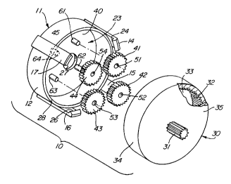
Figure 2 sets forth a perspective assembly view
of module 10 showing ring gear rotor 30 in partial
section. As described above, module 10 includes a
housing 11 having a generally cylindrical shape and
defining a cylindrical wall 12. Housing 11 further
defines a generally planar back wall 40 supporting a
plurality of posts 61, 62, 63, and 64 which receive
and rotatably support a plurality of planetary gears
41, 42, 43, and 44. Gears 41 through 44 are secured
to posts 61 through 64 in a rotatable attachment in
which posts 61 through 64 are received within
apertures 51 through 54 formed respectively in gears
41 through 44.
Back wall 40 further defines a center aperture 45
which is aligned with the center line of the
arrangement of planetary gears 41 through 44.
Gear module 10 is completed by ring gear rotor 30
which, as described above, is generally cylindrical
and defines an outer face 35 and an outer wall 34. As
is also described above, rotor 30 supports a center
gear 31 extending forwardly from outer face 35. As
can be seen by the broken section of Figure 2, ring
gear rotor 30 defines an interior cavity 33 and an
internal ring gear 32. In accordance with
conventional ring gear fabrication, internal ring gear
32 will be understood to extend the entire
circumference of ring gear rotor 30. With planetary
gears 41. through 44 received upon posts 61 through
64, rotor 30 is assembled to housing 11 such that
CA 02344813 2001-04-06
WO 00/11372 PCT/US99/16521
9
planetary gears 41 through 44 each engage internal
ring gear 32. In this fabrication, and as is better
set forth below in Figure 3, the resulting assembly
allows the insertion of a center gear identical to
center gear 31 through aperture 45 of back wall 40 to
mutually engage each of planetary gears 41 through 44.
In planetary gear systems, the center gear commonly
coupled to the plurality of planetary gears is
referred to as the "sun" gear.
In operation, the completed and assembled gear
module formed by housing 11, gears 41 through 44, and
ring gear rotor 30 produces the module shown in Figure
1 in which rotation of rotor 30 produces corresponding
rotations of gears 41 through 44. Conversely, and in
accordance with the anticipated use of the present
invention, a gear substantially identical to gear 31
is inserted through aperture 45 engaging gears 41
through 44. The resulting gear system of module 10
provides rotation of ring gear rotor 30 in response to
such rotation of an inserted center gear. Conversely,
rotation of ring gear rotor 30 produces a rotation of
the inserted center gear.
It will be apparent to those skilled in the art
that ring gear rotor 30 is securely joined to center
gear 31. Thus in essence, center gear 31 provides the
output gear of gear module 10. It will also be
appreciated, and as is better seen in Figure 3, that
module 10 once completed is configured to receive an
identical gear module in a nesting arrangement in
which center gear 31 becomes the input gear passing
through the aperture formed in the next gear module in
the manner shown in Figure 3 as center gear 31 passes
through aperture 86 of housing 81 of module 80.
CA 02344813 2001-04-06
WO 00/i 1372 PCTNS99/16521
The speed and torque relationship between the
input gear inserted through center aperture 45 and the
output gear provided by center gear 31 is determined
by the relative sizes of the center gear, the
5 planetary gears, and the internal ring gear of the
module. Thus for any given fabrication of module 10,
there exists a drive characteristic such as speed
reduction and torque multiplication which, in essence,
defines the gear module. It will also be noted that
10 successive gear modules having defined characteristics
of gear ratio and torque ratio are multiplied when two
or more gear modules are nested and engaged as set
forth below in Figure 3.
Figure 3 sets forth a section view of a planetary
gear system utilizing a plurality of gear modules
coupled in a serial or stacked configuration. In the
example shown in Figure 3, a motor 70 fabricated in
accordance with conventional fabrication techniques,
includes an output shaft 71 supporting an output gear
72. Figure 3 is intended to illustrate the nested or
stacked configuration of a number of substantially
identical gear modules to produce an overall gear
ratio between output gear 72 of motor 70 and the final
output gear of the end module (gear 134 of module
110). As mentioned above, the final ratio of speed
and torque provided by the combined gear modules shown
in Figure 3 is the multiplication of each gear module
ratio. It will be apparent, therefore, that the
number of modules which are assembled to form the
complete gear system operated by motor 70 is not
limited to the three modules shown in Figure 3. On
the contrary, Figure 3 is intended to illustrate an
indefinite number of modules continuing in succession
in the same manner as modules 10 and 8o are coupled
and engaged which indefinite number extends from motor
CA 02344813 2001-04-06
WO 00/11372 PCTNS99/16521
11
70 to an end cap 140 at the opposite end of the gear
system.
More specifically, and as described above, module
10 includes a generally cylindrical housing il having
a back wall 40 and an interior cavity 23. Back wall
40 further defines a center aperture 45 and a
plurality of forwardly extending posts 61 through 64
(posts 62 and 64 seen in Figure 2). Housing 11
further defines an edge 28 and a plurality of
forwardly extending spring clips such as spring clips
14 and 16. Spring clip 14 defines a gripping edge 24
while spring clip iG defines a gripping edge 26.
Within housing 11, a ring gear rotor.30 defines
an interior cavity 33 and a center gear 31. Ring gear
rotor 30 further defines an internal ring gear 32
extending about the outer wall of ring gear rotor 30.
Module 10 is assembled in the manner described above
in Figures 1 and 2 and is completed by the insertion
of ring gear rotor 30 into interior cavity 23 of
housing 11 such that ring gear 32 engages planetary
gears 41 through 44 (gears 42 and 44 seen in Figure
2). Motor 70 and shaft 71 are positioned with respect
to module 10 such that output gear 72 is inserted
through aperture 45 and commonly engages each of
planetary gears 41 through 44 (gears 42 and 44 seen in
Figure 2). Thus the combination of motor 70, shaft
71, and output gear 72 operatively coupled to gears 41
through 44 of module 10 together with the assembly of
ring gear rotor 30 into interior cavity 23 completes a
gear module in which a gear ratio of speed and torque
is defined between output gear 72 of motor 70 and
center gear 31 of rotor 30.
CA 02344813 2001-04-06
WO 00/11372 PCT/US99/16521
12
If desired, a single module may be used in the
manner in which gear module 10 is assembled to output
gear 72 if desired. In such case, end cap 140 is
substituted for module 80 to complete the gear system.
For purposes of illustration, however, and in
accordance with an important aspect of the present
invention, the inventive gear system is not limited to
a single gear module but rather may be enhanced by the
attachment of one or more additional modules. For
purposes of illustration, a gear module 80 which is
substantially identical to gear module 10, is secured
to gear module 10 by the cooperation of edge 28 of
housing 11 and spring clips 14 through 17 (clips 13
and 17 shown in Figure 2).
More specifically, module 80 includes a generally
cylindrical housing 81 having a cylindrical wall 94
and a center aperture 45. Housing 81 supports a
plurality of forwardly extending posts such as posts
96 and 98 which support planetary gears 97 and 99 in a
rotatable attachment. Housing 81 further defines an
edge 82 and a plurality of forwardly extending spring
clips such as spring clips 90 and 91. It will be
apparent to those skilled in the art that in the
preferred embodiment of the present invention, housing
81 supports a greater plurality of forwardly extending
spring clips similar to those shown in Figure 2 for
module 10. However, the number of spring clips for
any given module is subject to variation should the
user desire in meeting certain design requirements.
It is equally feasible to select nested or stacked
gear modules which are constructed in accordance with
gear module 10 but which have different gear sizes to
produce different gear ratios. However, in the
preferred fabrication of the present invention, gear
CA 02344813 2001-04-06
WO 00/I1372 PCT/US99116521
13
module 80 is substantially identical to gear module
10.
Module 80 further includes a ring gear rotor 83
having an internal ring gear 95 and a center gear 85.
As was the case in the assembly of module 10, ring
gear rotor 83 is received upon the plurality of
planetary gears such as gears 97 and 99 in engagement
with internal ring gear 95.
The multiple module gear system shown in Figure 3
provides a plurality of stacked or nested gears
coupled between module 10 and the final gear module
110. Thus each successive module is secured to the
preceding module by the engagement of spring clips
having gripping edges and the outer edge of the
succeeding housing. Thus module 80 having spring
clips 90 and 91 which define gripping edges 92 and 93
will be understood to couple to and engage the next
succeeding gear module in the manner in which spring
clips 14 and 16 engage housing 81 of module 80.
Module 110 together with end cap 140 show the
cooperation of the last or end most module and end cap
140. Assuming a module preceding module 110 supports
a center gear 100, module 110 includes a housing 111
defining an aperture 113 through which center gear 100
extends in the manner described above for modules 10
and 80. Module 110 is preferably formed substantially
identical to module 10 and thus includes a housing 111
supporting a plurality of posts such as posts 125 and
131, each of which supports a rotatable planetary gear
such as gears 124 and 130. Module 110 further
includes a ring gear rotor 132 having an internal ring
gear 133. Once again, as described for previous
modules, ring gear rotor 132 is received within
CA 02344813 2001-04-06
WO 00/11372 PCT/US99/16521
14
housing 111 such that internal ring gear 133 engages
the planetary gears of the module such as gears 124
and 130. Housing 111 includes a plurality of
forwardly extending spring clips such as spring clips
120 and 122 having respective gripping edges such as
edges 121 and 123. Ring gear rotor 132 further
includes a forwardly extending center gear 134.
To complete the assembly of the gear system
provided by modules 10 through 110, an end cap 140 is
secured to housing 111 of module 110 to maintain the
captivity of ring gear rotor 132 within housing 111.
Thus end cap 140 is generally cylindrical in shape and
defines a center aperture 142, a forward edge 141, and
a back 143. As is shown in Figure 3, the assembly of
end cap 140 to module 110 is carried forward in
substantially the same manner as assembly between
successive gear modules in that the spring clips of
module 110 such as clips 120 and 122 are received upon
the outer surface of end cap 140 and snap-fit thereto
through the engagement of the respective gripping
edges of the spring clips such as edges 121 and 123 of
spring clips 120 and 122.
With the entire gear system assembled in the
manner shown in Figure 3, the gear ratio or ratio of
speed and torque between output gear 72 of motor 70
and the final module gear shown as center gear 134 of
module I10 is determined by the multiplication of the
individual ratios of each module. Thus for example,
if modules 10, 80, and 110 form the entire combination
gear system, and if each is a 4 to 1 speed reduction
gear set, the overall gear ratio of the system is 64
to 1. That is to say four times four times four. If
two gear modules are used in the system and each has a
CA 02344813 2001-04-06
WO 00/11372 PCT/US99/16521
4 to 1 gear ratio, then the system exhibits a 16 to 1
overall gear ratio.
Once again, it will be understood that different
5 gear ratios may be provided by the various modules
which are nested or stacked together in accordance
with the present invention. However, once again it
must be mentioned that the preferable fabrication of
the present invention is that in which the individual
10 gear models are substantially identical both in
structure and in gear ratio. This facilitates the
high volume production of a great number of identical
gear modules which may then be combined in the
appropriate number in a given fabrication or design to
15 produce the overall gear ratio desired. While the
module of the present invention may be fabricated
using virtually any sufficiently rigid material, it
has been found extremely advantageous to utilize the
present invention module gear system using low cost
injection molded plastic components which are
relatively strong and rigid, relatively quiet in their
operation, and which are well suited to low cost, high
volume production.
It will be apparent to those skilled in the art
that the use of the present invention modulized gear
system is not limited to the illustrated use in which
a motor drives the gear module input and a gear shaft
forms its output. As with many gear systems, the
system of the present invention is bidirectional in
that the roles may be reversed between input and
output. Thus, for example, power may be applied to
center gear 134 in the system of Figure 3 and the
driven output gear may take the place of output gear
72 of motor 70. In such case, motor 70 may be any
load such as a generator or lifting device without
CA 02344813 2001-04-06
WO 00/11372 PCT/US99/165Z1
16
departing from the spirit and scope of the present
invention.
While particular embodiments of the invention
have been shown and described, it will be obvious to
those skilled in the art that changes and
modifications may be made without departing from the
invention in its broader aspects. Therefore, the aim
in the appended claims is to cover all such changes
and modifications as fall within the true spirit and
scope of the invention.