Note: Descriptions are shown in the official language in which they were submitted.
CA 02344979 2001-04-25
DRAIN PUMP MOUNTED PRESSURE SWITCH
FOR A WASHING MACHINE
BACKGROUND OF THE INVENTION
The present invention relates to a method and
apparatus for controlling the liquid level in a washing
machine.
A typical washing machine controls the water fill
level of the tub by use of an air dome, including a
pressure switch in communication with a sealed tube.
The open end of the tube is in communication with the
bottom of the wash tub and extends upward toward the
pressure switch. As water enters the wash tub and the
sump, water enters the opening of the air dome hose
and, as the water level rises, the air pressure in the
sealed tube increases and ultimately trips the pressure
switch. When the pressure switch trips, the washing
machine stops filling. One example of a typical air
dome is disclosed in U.S. Pat. No. 3,397,716.
One major problem with prior art air domes occurs
when water enters the air dome hose. When water does
enter the air dome hose, the water does not always come
out due to the vacuum caused by the sealed hose. When
this happens, the fill level of the washing machine
increases since a greater fill level is required to
trip the pressure switch. The fill level required to
trip the pressure sensor will increase by an amount
equal to the length of the water column trapped in the
air dome hose. In other words, if six inches of water
are trapped in the air dome hose, the level at which
the washing machine will quit filling is increased by
six inches. It is possible that the increased fill
level will cause the washing machine to overflow.
1
CA 02344979 2003-12-30
A common way that water becomes trapped in the air
dome hose is when a small amount of water is left in
the sump at the bottom of the wash tub. When the
washing machine is tipped, for moving or maintenance
for example, water will flow into the hose and will not
come out. When this happens, the next time the washing
machine is filled, the water level required to trip the
pressure switch will be greater by an amount equal to
the amount of water trapped in the air dome hose.
Another problem associated with prior art air dome
hoses, such as that disclosed in patent 5,964,001, is
the formation of condensation in the small diameter
tube extending between the air dome and the pressure
switch. Such condensation forms as a result of changes
in the water temperature from hot to cold. Such
condensation is hard to drain from the small diameter
tube due to surface tension. Eventually, the
condensation can migrate upwardly along the tube to the
switch, and cause failure of the switch.
Another problem can arise if the pressure switch
is mounted above the tub, as in the '001 patent. If
there is a leak in the air dome, there will be no
change in air pressure within the dome in response to
changing water levels. Therefore, the switch will not
actuate, leading to overflow of the washing machine
tub.
Accordingly, a primary feature of the present
invention seeks to provide a pressure switch for
controlling the water level in a washing machine
without the problems associated with the prior art.
Another feature of the present invention seeks
to provide an air dome pressure switch which is mounted
to the drain pump of the washing machine.
2
CA 02344979 2003-12-30
Another feature of the present invention seeks to provide
a pressure switch which is mounted below the tub so as to be
actuated by water pressure in the event of an air leak in the
air dome.
A further feature of the present invention seeks to
provide a pressure switch which is mounted adjacent the air
dome so as to minimize or preclude formation of condensation.
Another feature of the present invention seeks to provide
a sensor for controlling water level in washing machine tub,
which is mounted independently of the tub.
A further feature of the present invention seeks to
provide a sensor for controlling water level in a washing
machine, which is economical to manufacture, and effective and
durable in use.
These and other aspects will become apparent from he
following description of the invention.
SUN~iARY OF THE INVENTION
The invention in one broad aspect pertains to a pressure
switch assembly for controlling water level in a washing
machine, the machine including a cabinet with a base, a tub
mounted in the cabinet, a drain pump with a water inlet line
in fluid communication with the tub and a water outlet line
for discharging water from the tub. The assembly comprises: an
air dome in fluid communication with the inlet line of the
pump; and a pressure switch mounted directly on the air dome
and being in fluid communication therewith so as to sense air
pressure in the air dome. Preferably, the pressure switch is
angularly disposed relative to the air dome to allow
condensation to drain from the pressure switch.
Another aspect of the invention provides a device for
controlling water level in a washing machine having a wash tub
and a pump with an inlet and outlet for draining water from
the tub, comprising: an air pressure sensor mounted on the
pump; an air dome disposed between the air pressure sensor and
the pump inlet so that the air pressure sensor senses air
pressure changes in the air dome resulting from water level
3
CA 02344979 2003-12-30
changes in the tub.
Further, the invention provides a pump and air dome
assembly for controlling water level in a washing machine,
comprising a pump housing, a water inlet leading to the pump
housing, a water outlet directed away from the pump housing,
and an air dome formed on the water inlet and an air pressure
sensor connected to the air dome for sensing air pressure
within the air dome. In one aspect, a support bracket extends
from the pump housing for mounting the air pressure sensor,
l0 whereas in another aspect, the pump housing, water inlet,
water outlet and air dome are integrally formed.
More particularly, the water level control pressure
switch of the present invention is mounted to the drain pump
of a washing machine, independently of the washing machine
tub. An air dome extends from the water inlet line of the
pump, so as to be partially filled with water during the fill
cycle of the washing machine. The pressure switch is mounted
directly to the air dome. The switch is angularly disposed to
allow condensation to drain away from the switch. Since the
pressure switch is mounted to the drain pump below the tub of
the washing machine, in the event of an air leak in the air
dome, the switch will still be actuated by water pressure,
thereby preventing overflow of the tub. The
30
3A
CA 02344979 2001-04-25
pump housing, pump inlet, pump outlet, and air dome are
integrally formed.
BRIEF DESCRIPTION OF THE DRAWINGS
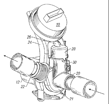
Figure 1 is a perspective view of the pressure
switch of the present invention mounted upon a drain
pump of a washing machine.
Figure 2 is an end view of the switch and pump
assembly.
Figure 3 is a side elevation view of the pump and
switch assembly.
Figure 4 is a bottom plan view of the pump and
switch assembly.
DETAILED DESCRIPTION OF THE DRAWINGS
The present invention is directed towards a sensor
or pressure switch 10 adapted to control the water
level in a washing machine tub. The switch 10 is
mounted upon the drain pump 12 of the washing machine.
The pump I2 is secured to the base 14 of the washing
machine cabinet (not shown). The pump 12 includes a
plurality of feet 16 adapted to extend through keyholes
18 in the base 14 and twist lock to secure the pump 12
to the base 14. The pump 12 includes a water inlet
line 20 and a water outlet line 22. A motor I3 is
operatively connected to the circuitry of the washing
machine to control operation of the pump 12. The pump
12 includes a housing 21 and an impeller 23.
The switch 10 is angularly mounted upon a support
bracket 24. The switch 10 includes an air inlet 26
which is connected to a cap 28 on a stand pipe 30.
Preferably, the support bracket 24, stand pipe 30, pump
inlet 20, pump outlet 22 and pump housing 21 are
4
CA 02344979 2001-04-25
integrally formed of molded plastic. The feet 16 may
also be integrally formed with the housing 21. The
stand pipe 30 has a relatively large diameter and is in
fluid communication with the water inlet line 20 of the
pump 12, so as to be partially filled with water during
the fill cycle of the washing machine. The stand pipe
30 functions as an air dome. The water inlet 20 of the
pump 12 is connected to the water outlet opening of the
washing machine tub, such that changes in water level
within the tub produce a corresponding change of the
air pressure within the air dome stand pipe 30. The
air pressure changes are sensed by the switch 10, which
is actuated so as to control the water level in the
tub.
In operation, at the beginning of the wash cycle,
the wash tub will begin filling the water. The pump 12
is not actuated during the water fill cycle. As the
water level increases in the tub, the pressure of the
air inside the air dome 30 increases in proportion to
the water level, via water in the inlet 20 and stand
pipe 30. When the air pressure reaches a predetermined
level, as sensed by the switch 10, the switch is
actuated to stop the flow of water into the tub.
The relatively large diameter of the stand pipe 30
minimizes or precludes the formation of condensation
resulting from changing water temperatures in the inlet
26 of the switch 10. Also, the angular orientation of
the switch 10 on the bracket 24 allows any condensation
which forms to drain from the air inlet 26.
If an air leak develops in the stand pipe or air
dome 30, for example, from a failed seal between the
cap 28 and the stand pipe or air dome 30, water
pressure in the inlet line 20 and stand pipe 30 will
5
CA 02344979 2001-04-25
eventually actuate the switch 10, since the switch 10
is located beneath the tub. Preferably, the switch 10
is a diaphragm-type switch, with the electrical
contacts being on the opposite side of the diaphragm
from the air inlet 26, such that in the event of an air
leak, water will not damage the switch.
In conventional horizontal axis washing machines,
the tub is hung from the cabinet and floats upwardly
and downwardly in response to the load in the tub.
Since the sensor or pressure switch 10 of the present
invention is mounted to the drain pump 12 on the base
14 of the cabinet, movement of the tub due to varying
clothes loads provides a relative difference in height
between the tub and air dome 30, therefore varying the
air pressure within the air dome 30. Accordingly, as
the tub drops with a heavier load of laundry, the
pressure in the air dome 30 is reduced, causing the
pressure switch 10 to be actuated later so as to
provide additional water in the tub for the larger
load. Conversely, with the light load, the tub remains
at a higher elevation, such that the switch will be
activated earlier, thereby providing less water to a
lighter laundry load. Thus, varying water levels are
provided within the tub depending upon the load size,
with the present invention functioning as a load
sensor.
The preferred embodiment of the present invention
has been set forth in the drawings and specification,
and although specific terms are employed, these are
used in a generic or descriptive sense only and are not
used for purposes of limitation. Changes in the form
and proportion of parts as well as in the substitution
of equivalents are contemplated as circumstances may
6
CA 02344979 2001-04-25
suggest or render expedient without departing from the
spirit and scope of the invention as further defined in
the following claims.
7