Note: Descriptions are shown in the official language in which they were submitted.
CA 02345194 2001-04-25
Lxpress Mail #EJ532340698US
Case No. 12239/78053 -1- Mailed on 5-5-2000
STRAPPER WITH IMPROVED WINDING AND CUTTING ASSEMBLY
Field of the Invention
This invention pertains to strapping machines. More particularly, the
present invention pertains to an improved drive arrangement for a strapping
machine including a rewind member and cutting arrangement.
Background of the Invention
Strapping machines are in widespread use for applying a strap, such as a
plastic strap, in a tensioned loop around a load. A typical strapping machine
includes a strap chute for guiding the strap around the load, a strapping head
through which the leading end of the strap is fed, and a strap dispenser to
dispense a desired length of strap from a coil of strap material.
The strapping head carries out a number of functions. It advances the
strap along the chute around the load until the leading end returns to the
strapping head and retracts or rewinds the strap from the chute to produce
tension in the strap around the load. The strapping head typically includes an
assembly for securing the strap in the tensioned loop around the load such as
by
welding the strap to itself at its overlapping portions.
A typical strapping head includes a pair of advancing rollers for
advancing the strap through the strapping head and a pair of retraction
rollers for
retracting the strap to, for example, take-up the strap. The head also
includes a
winder or tensioner that rewinds or takes up the strap after it is positioned
around the load so as to apply a tension in the strap. In one known
configuration, the winder includes a split-type rotating element that has a
channel or slot formed therethrough to essentially define split halves of the
winder. The split halves are fixed relative to one another and the strap
traverses
through the slot between the halves. Upon an appropriate signal, the winder is
actuated and rotates to tension the strap.
CA 02345194 2006-02-16
-2-
In a typical winder anrangement, the strap is not in tension until it passes
over itself around the winder, thus creating sufficient friction to prevent
the strap
from slipping through the winder slot. It has been observed that often, the
winder must rotate in excess of 360 degrees, and with some types of readily
compressible loads, it must rotate more than 720 degrees to provide sufficient
friction to begin tensioning and to provide the appropriate tension on the
strap.
In known strapping heads, the winder is positioned intermediate the feed
and retraction rollers. An arrangement such as this disclosed in U.S. Patent
No.
4,605,456 which patent is assigned to the assignee of the present application
and
may be referred to for further details. Although the strapping machine
disclosed
in this patent functions well, it does have certain drawbacks. For example, it
has
been found that in known strapping machines, the strap may not automatically
refeed after faulted strap is ejected following a jam in the machine or after
significant rewinding following load compression. It has also been found that
in
known strapping head configurations, adjustments may also be necessary in
order to accommodate varying gauges of the strap material. It has fiu-ther
been
found that the rewinding length may be limited due to structural constraints
of
the strapping head, winder and drive arrangement.
Accordingly, there exists a need for a strapping machine having a winder
that commences effective tensioning of the strap without the strap having to
wind over itself. Desirably, such a winder is effective over a range of strap
gauges and can be used with highly compressible loads. More desirably, such a
winder permits positioning the winder within the strapping head so as to take
advantage of automatically refeeding the strap through the strapping heading
following faulted strap ejection.
Summarv of the Invention
A strapping machine for positioning a strap material around an
associated load and tensioning the strap material around the load includes a
CA 02345194 2001-04-25
-3-
frame for supporting the load, a chute positioned on the frame for receiving
the
strap material and orienting the strap material around the load, a strap
supply and
a strapping head for extracting the strap from the supply, feeding the strap
through the chute around the load, passing the strap from the chute around the
load, retracting and tensioning the strap.
The strapping head includes feed rollers and retraction rollers for feeding
and retracting the strap and a winder for tensioning the strap around the
load.
Preferably, the winder includes a rotating head portion having a stationary
element and a pivotal element, cach defining an outer surface around which the
strap material is wound. The stationary and pivotal elements define a slot
therebetween for receiving the strap material. Each element defines a gripping
portion at about a respective end that is opposingly facing the other of the
gripping portions.
The pivotal element is pivotal between an open position in which the
gripping portions are spaced from one another and a closed position in which
the
gripping portions cooperate with one another to engage and secure the strap
material therebetween. The winder rotates from a home position in which the
winder is in the open position and an other than home position in which the
winder is in the closed position to exert a tension in the strap. In a most
preferred embodiment, the winder is positioned between the feed and retraction
rollers and the strap supply.
In a preferred winder, the pivotal element is biasedly mounted to the head
portion into the closed position and includes a projection extending from the
pivotal
element for maintaining the pivotal element in the open position when the
winder is
in the home position.
The winder includes a drive assembly for rotating the winder liead portion.
Preferably, the winder includes a winder biasing element, such as a clock-type
spring for returning the winder to the home position.
CA 02345194 2001-04-25
-4-
The strapping machine can include one or more intermediate stop plates
positioned between the winder head portion and the frame. The intermediate
stop
plates pennit greater than 360 degree rotation of the winder relative to the
strapping
machine.
A preferred embodiment of the strapping machine includes a cam having a
feed surface, a retraction surface and an intermediate surface and a linkage
assembly for actuating the feed rollers, the retraction rollers and the
winder. The
preferred linkage includes a single cam-contacting linkage arm configured to
bear
against the cam.
The linkage is configured to move the feed rollers into engagement with the
strap material and to move the retraction rollers out of engagement with the
strap
material when the cam-contacting linkage arm bears against the feed surface.
The
linkage is further configured to move the retraction rollers into engagement
with
the strap material and to move the feed rollers out of engagement with the
strap
material when the cam-contacting linkage arm bears against the retraction
surface.
The linkage further moves the feed rollers and the retraction rollers out of
engagement with the strap material when the cam-contacting linkage arm bears
against the intermediate surface.
To this end, the linkage assembly includes a second linkage arm configured
to bear against the single, cam-contacting linkage arm. The cam-contacting
linkage
ann is configured to move the feed rollers into and out of engagement with the
strap material and the second linkage arm is configured to move the retraction
rollers into and out of engagement with the strap material.
A most preferred embodiment of the strapping machine includes a cutting
assembly positioned between the feed rollers and the retraction rollers. The
cutting
assembly includes a stationary anvil and a rotating cutting blade defining a
pivot.
The cutting assembly further includes a drive assembly having a motor and a
cam-
follower mounted thereto.
CA 02345194 2006-02-16
-5-
A linkage member is operably mounted to the rotating cutter and has an
elongated slot
formed therein. The cam-follower is configured for receipt in and movement
through the
elongated slot. Actuation of the motor moves the cam-follower through the
elongated slot to
rotate the blade into engagement with the anvil. The blade engages the anvil
when the cam-
follower is at about a farthest-most position from the pivot.
In a preferred embodiment, the retraction rollers engage the strap following
actuation
of the cutting assembly. Most preferably, an ejection chute disposed between
the feed rollers
and the retraction rollers, and the faulted strap is ejected by the retraction
rollers through the
chute.
One feature of the invention pertains to a winder for a strapping machine that
positions
a strap material around a load and tensions the strap material around the
load. The winder
includes a rotating head portion having a stationary element and a pivotal
element, the
stationary and pivotal elements each defining an outer surface around which
the strap material
is wound and defining a slot therebetween for receiving the strap material.
The stationary and
pivotal elements each define a gripping portion at about respective ends
opposingly facing one
another, the pivotal element being pivotal between an open position in which
the gripping
portions are spaced from one another and a closed position in which the
gripping portions
cooperate with one another to engage and secure the strap material
therebetween. The
rotating head portion includes a biasing element for biasing the head portion
into the closed
position.
In one aspect, the winder rotates from a home position in which the winder is
in the
open position and an other than home position in which the winder is in the
closed position.
In another aspect the winder rotates from a home position in which the winder
is in
the open position and an other than home position in which the winder is in
the closed
position, the winder including a projection extending from the pivotal element
for maintaining
the pivotal element in the open position when the winder is in the home
position, and for
maintaining the winder in the home position.
The invention also comprehends a strapping machine for positioning a strap
material
around an associated load and tensioning the strap material around the load,
comprising a
frame for supporting the load, a chute positioned on the frame for receiving
the strap material
CA 02345194 2006-02-16
-5A-
and orienting the strap material around the load, and a strap supply. A
strapping head is
provided for extracting the strap from the supply, feeding the strap through
the chute around
the load, passing the strap from the chute around the load, retracting and
tensioning the strap.
The strapping head includes feed rollers and retraction rollers for feeding
and retracting the
strap and a winder for tensioning the strap around the load the winder
includes a rotating head
portion having a stationary element and an element movable toward and away
from the
stationary element, the stationary and movable elements each defining an outer
surface around
which the strap material is wound and defining a slot therebetween for
receiving the strap
material. The movable element is movable between an open position in which the
strap freely
moves through the slot and a closed position in which the stationary and
movable elements
cooperate with one another to engage and secure the strap material
therebetween. The winder
rotates from a home position in which the winder is in the open position and
an other than
home position in which the winder is in the closed position to engage and
secure the strap in
the slot.
Other features and advantages of the present invention will be apparent from
the
following detailed description, in conjunction with the appended claims.
Brief Description of the Figures
FIG. 1 is front view of a strapping machine illustrating, generally the
components and
arrangement thereof, the machine shown with a strapping head embodying the
principles of
the present invention;
FIG. 2 is a front perspective view of the strapping head, the strapping head
shown
with portions of the frame removed for clarity of illustration, the head
further shown without
strap material positioned therein;
FIG. 3 is a front/side perspective view of the strapping head of FIG. 2 shown
with
other portions of the frame removed for clarity of illustration, this view
shown with strap
material traversing through the head in a normal travel path;
FIG. 4 is a rear perspective view of the strapping head of FIG. 3, again
illustrated with
portions of the frame removed for clarity of illustration;
FIG. 5 is a front perspective view of the winder and intermediate stop plate,
the
winder being shown in partial cross-section;
CA 02345194 2001-04-25
-6-
FIG. 6 is an exploded view of the winder also shown with an
intermediate stop plate; and
FIGS. 7a-d are schematic views of the relative rotation of the winder and
stop plate shown through about 720 degrees of revolution; and
FIG. 8 is rear schematic view of the strapping head illustrating the
positions of the cutter linkage as it moves through one cutting and eject
cycle.
Detailed Description of the Preferred Embodiments
While the present invention is susceptible of embodiment in various forms,
there is shown in the drawings and will hereinafter be described a presently
preferred embodiment with the understanding that the present disclosure is to
be
considered an exemplification of the invention and is not intended to limit
the
invention to the specific embodiment illustrated.
Referring to the figures and in particular, to FIG. 1, there is shown a
strapping machine 10 having a strapping head 12 embodying the principles of
the
present invention. The strapping machine 10 includes generally a workstation
14
such as the illustrated tabletop on which the load may be rested during the
strapping
operation. The machine 10 further includes a chute 16 around which the strap S
is
advanced during the strapping operation and one or more strap dispensers 18
from
which the strap S is dispensed to the strapping head 12. The overall
arrangement
and operation of such a strapping machine 10 is disclosed in U.S. Patent Nos.
4,605,456 and 5,299,407.
The strapping head 12 is that portion of the machine 10 that withdraws or
pulls the strap S from the dispenser 18, feeds the strap S through the chute
16,
grasps the leading edge of the strap so as to bring it into contact with a
trailing
portion, and tensions the trailing portion so as to compress the load.
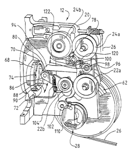
Referring now to FIGS. 2-4, the strapping head 12 includes a frame 20, a
plurality of feed rollers 22a,b and a plurality of retraction rollers 24a,b.
In the
illustrated embodiment, two such feed rollers 22a,b and two such retraction
rollers
CA 02345194 2001-04-25
-7-
24a,b are shown. In this embodiment, one of the feed rollers is a driven
roller 22a
while the other is an idler roller 22b that rotates only in frictional
cooperation with
its associated, driven roller 22a. Likewise, one of the retraction rollers is
a driven
roller 24a and the other is an idler roller 24b that rotates only in
frictional
cooperation with its associated driven roller 24a. The driven rollers 22a, 24a
are
driven by, for example, the exemplary belts drives 26. Those skilled in the
art will
recognize other arrangements by which the rollers 22a, 24a can be driven.
The strapping head 12 includes a biased, pivotal winder 28 that cooperates
with the feed and retraction rollers 22, 24. As shown in FIGS. 2-3, the winder
28 is
disposed in close proximity to the feed and retraction rollers 22, 24. Unlike
known
strapping machines, which position the winder between the feed and retraction
rollers, in a preferred embodiment of the present machine 10, the winder 28 is
positioned upstream of the feed and retraction rollers 22, 24. For purposes of
the
present discussion, upstream shall mean that side of the strapping head 12
from
which the strap S material is fed (i.e., between the strapping head 12 and the
dispensers 18) and downstream shall mean that side of the strapping head 12 to
which the strap S is fed, (i.e., toward and around the chute 16).
As provided above, the winder 28 functions to produce tension in the strap
S after the strap S is fully distributed around the load, and the "slack" in
the strap S
has been taken-up (i.e., after the strap S has been retracted). For example,
after the
strap S has been positioned around the load and in overlapping relation with
itself,
the retraction rollers 24a,b are actuated to retract the strap S to take-up
any slack in
the strap. The winder 28 is then actuated to further pull the strap S. In this
manner,
it exerts a tension in the strap S which compresses or bundles the load.
To this end, in the illustrated embodiment, the winder 28 is shown as having
a generally circular profile, that is defined by a pair of generally
semicircular
elements 30, 32 forming a slot or channel, as indicated at 34, between the
elements
30, 32. The slot 34 is sized to accommodate a range of strap gauges
(thicknesses)
CA 02345194 2001-04-25
-g-
and to permit the strap to move freely through the slot 34 during the feeding
and
retraction operations of the strapping machine 10.
Unlike known rewinding devices, which include stationary halves mounted
on a rotating shaft, the present winder 28 includes a stationary element 30
and a
pivotal or hinged element 32. Referring now to FIGS. 5-6, the stationary
element
30 is mounted to (or formed as part of) a back plate 36 which in turn is
mounted to
or formed as part of a shaft 38 about which the winder 28 rotates. The pivotal
or
hinged element 32 pivots relative to the stationary element 30 about a pivot
pin 40
positioned at the upstream side, as indicated at 42, of the winder 28. The
stationary
and pivotal elements 30, 32 define a variable gap therebetween. At the
upstream-
most side 42 of the winder 28, the stationary and pivotal members 30, 32
define
gripping portions 44, 46 that grip or pinch the strap S therebetween during
the
winding operation.
The pivotal element 32 is biased by, for example, a coil spring 48, into a
position so that the stationary and pivotal element gripping portions 44, 46
contact
one another, i.e., are biased into a closed position. The pivotal element 32
includes
an upper stop pin 50 that extends fully through a notched opening 52 in the
back
plate 36. The upper stop pin 50 is configured to contact an intermediate stop
plate
54, discussed below, to maintain the pivotal element 32 in the open position
during
strap S feed and retraction operations. The notched opening 52 in the back
plate 36
permits the pivotal element 32 to be maintained in the open position when the
winder 28 is at the home position.
To permit the winder 28 to rotate more than 360 degrees without
interference by the upper stop pin 50 preventing such rotation, the
intermediate stop
plate 54 is mounted between the winder 28 and the frame 20. The intermediate
stop plate 54 rotates about the winder shaft 38 and includes a winder stop 56
and a
frame stop 58. These stops 56, 58 extend in opposing directions,
longitudinally
from about a periphery 60 of the stop plate 54. An exemplary plate 54 is
illustrated
CA 02345194 2001-04-25
-9-
in FIG. 6. The winder stop 56 is that stop against which the upper stop pin 50
bears
to maintain the winder 28 open in the home position.
The winder 28 further includes a winder spring 62, such as the exemplary
clock-type spring that is mounted to the shaft 38 to return the winder 28 to
the
home position after the winding operation.
Again, also unlike known strapping heads, the present strapping head 12
utilizes a single cam 68 having a plurality of camming surfaces 70, 72, 74 for
actuating a linkage arrangement 76 that engages and disengages the feed and
retraction rollers 22, 24. The linkage arrangement 76 is better seen in the
rear view
of the strapping head 12 in FIG. 4. As will be recognized by those skilled in
the art,
the feed and retraction rollers 22, 24 are driven in opposite directions from
one
another, and either the feed 22 or retraction 24 rollers are engaged with the
strap S
at any given time. That is, if the feed rollers 22 are engaged with the strap
S to feed
the strap S, the retraction rollers 24 are disengaged from the strap S.
Conversely,
when the retraction rollers 24 are engaged with the strap S to take up slack
or
retract the strap S, the feed rollers 22 are disengaged from the strap S.
Additionally, when the winder 28 is used to tension the strap S, both the
feed and retraction rollers 22, 24 are disengaged from the strap S. As such,
any one
of the three strap engaging portions of the strapping head 12 (the feed
rollers 22, the
retraction rollers 24 and the winder 28) operate on the strap S at any one
time.
The present linkage 76 operably connects these operated system portions
using a single cam 68 and a single cam-contacting bearing 80 to effectuate
proper
sequencing and operation of the strapping head 12. Referring to FIG. 4, the
linkage
76 includes a first or feed roller linkage arni 86 that is moved between an
engaged
position and a disengaged position (as indicated by the arrows at 88 and 90,
respectively), to engage and disengage the feed rollers 22, respectively. The
feed
roller linkage arm 86 pivots about a first pivot 92. A second or retraction
roller
linkage ann 94 pivots about a second pivot 96 between an engaged position and
a
disengaged position (as indicated by the arrows at 98 and 100, respectively)
to
CA 02345194 2001-04-25
-10-
engage and disengage the retraction rollers 24. The cam-contacting bearing 80
is
positioned on the feed roller linkage arm 86.
The cam 68 includes three operating surfaces. A first (highest or feed)
surface 70 urges the feed roller linkage 86 into the engaged position 88. An
eccentric secondary linkage 102 (FIG. 2) is mounted on and operably connected
to
the feed roller linkage 86. The idler feed roller 22b is mounted to the
eccentric
secondary linkage 102 and is brought into contact with the strap S to suppress
the
strap S against the driven feed roller 22a. The eccentric secondary linkage
102 is
biasedly connected to the feed roller linkage 86, by, for example, a coil
spring 104,
to assure that sufficient pressure is maintained on the strap S by the driven
feed
roller 22a so that the strap S is properly fed through the strapping head 12
and chute
16. When the cam-contacting bearing 80 bears on the second or third operating
surfaces (home or intermediate 72, and retraction or lowest surfaces 74,
respectively), the feed roller linkage 86 moves to the disengaged position 90
to
disengage the feed rollers 22a,b from one another and from the strap S.
The retraction roller linkage arm 94 rests on a second portion 82 of the cain-
contacting bearing 80 and is biased so that it maintains contact with this
portion 82
of the bearing 80. The retraction roller linkage arm 94 is connected to a
carriage
106 that pivots about the frame 20 at the second pivot 96 and biases the
linkage 94
against the bearing portion 82 and biases the retraction rollers 24a,b into
the
engaged position. Unlike the feed roller 22 arrangement, the driven retraction
roller
24a is moved into and out of contact with the idler roller 24b.
When the cam-contacting bearing 80 bears on the feed or home surfaces 70,
72 (highest and intermediate surfaces, respectively), the retraction roller
linkage 94
moves to the disengaged position 100 to disengage the driven retraction roller
24a
from the idler roller 24b and the strap S. As will be understood from a study
of the
figures, the retraction linkage 94 in these two positions is urged upwardly,
as
indicated by the arrow at 100, which pivots the retraction carriage 106 to
move the
driven retraction roller 24a away from the idler roller 24b. Converselv, when
the
CA 02345194 2001-04-25
-I1-
cam-contacting bearing 80 bears on the lowest or retraction surface 74, the
retraction linkage 94 moves downwardly, as indicated by the arrow at 98,
which, in
turn, moves the driven retraction roller 24a into contact with the strap S to
suppress
the strap S between the retraction rollers 24a,b to retract or take-up the
strap S.
During the rewinding or tensioning portion of the strapping cycle, the cam-
contacting bearing 80 again bears on the cam retraction surface 74 which moves
feed roller 24b into the disengaged position 90. During this portion of the
cycle,
the retraction rollers 24a,b must also be disengaged from one another and from
the
strap S. To this end, with reference to FIGS. 3 and 5-6, a second bearing 110
rides
along an outer periphery of the winder 28 and the intermediate stop plate 54.
As
the winder 28 begins to rotate, the second bearing 110 is urged out of a small
depression 112, 114 in each of the wiinder 28 and intermediate plate 54
peripheries.
The depressions 112, 114 are aligned with the second bearing 110 when the
winder
28 and the intermediate stop plate 54 are in the winder home position. The
second
bearing 110, which is mounted to the feed roller linkage 86, urges the feed
roller
linkage 86 upward which in turn moves the retraction roller linkage arm 94
upward.
The upward movement of the retraction roller linkage arm 94 moves the
retraction
rollers 24a,b into the disengaged position. The winder 28 then continues to
rotate
clockwise as seen in FIG. 5.
Referring now to FIGS. 5 and 7a-d, as the winder 28 moves off of the home
position as seen in FIG. 7a, the upper stop pin 50 moves out of contact with
the
intermediate plate winder stop 56. This permits the spring 48 to move the
winder
pivotal element 32 into the closed or gripping position. The friction
developed
between the gripping portions 44, 46 of the winder 28 and the strap S causes
the
winder 28 to immediately commence tensioning the strap S, without the strap S
having to wind onto itself to develop the necessary friction. The pivotal
configuration of the winder 28 further enhances the gripping of the strap S.
As the
winder 28 begins to rotate clockwise as seen in FIG. 5, the strap S exerts a
force F
on the pivotal element 32 that is tangential to the winder 28 and in a
direction
CA 02345194 2001-04-25
-12-
opposite to the rotation of the winder 28. This force F translates to a
increased
pressure applied to the strap S at the gripping portions 44, 46.
Referring again to FIGS.7a-d, the winder 28 and intermediate stop plate 54
are configured so that the winder 28 can rotate, in the winding mode, greater
than
360 degrees. As seen in FIG. 7a, as the winder 28 begins to rotate, the upper
stop
pin 50 moves off of a first side 56a of the winder stop 56 on the plate 54. As
the
winder 28 continues to rotate, approaching a 360 revolution (FIG. 7b), the
stop pin
50 contacts a second side 56b of the winder stop 56 which permits further
rotation
of the winder 28 and rotates the plate 54 (FIG. 7c). Continuing beyond the
first 360
degree revolution, as the winder 28 and stop plate 54 approach 720 degrees of
revolution (FIG. 7d), the frame stop 58 coritacts a stub or like projection
116
extending from the frame 20 which stops the winder 28 and plate 54. This
provides
a limit to rotation, which is advantageous from a machine 10 control
standpoint.
As will be recognized by those skilled in the art, additional intermediate
stop plates 54 can be positioned between the winder 28 and the frame 20 to
permit
rotation of the winder 28 beyond about 720 degrees. Each additional
intermediate
stop plate 54 provides an additional about 360 degrees of rotation. For
example, a
winder 28 having two intermediate plates 54 can rotate about 1080 degrees (360
degree rotation for the winder 28 plus 360 degree rotation for each of the two
intermediate stop plates 54). Those skilled in the art will recognize that the
degree
of rotation is slightly less than 360 degrees because of that portion of the
arc that is
needed to accommodate the winder and frame stops 56, 58, respectively.
In the next operational step, the strap S is grasped at about the location at
which the leading and trailing portions overlap. The leading and trailing
portions
of the strap are welded or otherwise joined to one another around the load to
maintain the load under compression. After the strap is fixed, e.g., welded
around
the load, the free end of the strap is cut and the load is removed from the
strapping
machine 10. This step of the operation is more fully disclosed in the
aforementioned U.S. Patent No. 4,605,546. Subsequently, the winder spring 62
CA 02345194 2001-04-25
-13-
returns the winder 28 to the home position, and the strapping machine 10 is
readied
for strapping a next load.
The strapping head 12 is configured so that in the event of a fault, the
strapping head 12 will sense the fault, automatically cut the strap S upon
receipt of
a fault signal and eject the strap from the machine 10. The head 12 will then
automatically refeed the strap S to ready the machine 10 for a next load. Such
an
arrangement for automatic fault-strap ejection is fully disclosed in Bell,
U.S. Patent
No. 5,640,899, which patent is assigned to the assignee of the present
application
and is incorporated by reference herein.
A cutter 78 includes a stationary cutting portion or anvil 120 and a rotating
cutting portion or blade 122. During normal strapping operations, the anvil
120
and blade 122 are spaced from one another and the strap S passes between them.
Upon receipt of a fault signal, the feed rollers 22a,b are disengaged from the
strap
S, and the cutter 78 is actuated. Referring to FIGS. 2, 4 and 8, the cutter 78
is
mounted to the frame 20 by an eccentric linkage arrangement 124. A pivot 126
of
the linkage 124 rotates a stub shaft 128 to which the cutting blade 122 is
attached.
The linkage 124 includes an elongated slot 130 at about a distal end 132 of
the
linkage 124 spaced from the pivot 126. The cutter drive includes a gear-type
motor
134 that rotates a shaft 136 having a cam-follower 138 mounted to an end
thereof.
The cam-follower 138 is positioned within the linkage slot 130. When the
cutter 78
is in the "rest" state (as indicated at 140), the cam-follower 138 is
positioned within
the slot 130 near to the pivot 126.
When the cutter 78 is actuated, the motor 134 drives the cam-follower 138
in an arc. As the cam-follower 138 moves through this arcuate path, it
traverses
through the slot 130 from the rest position 140, at which it is near to the
pivot 126,
to a position farthest from the pivot 126 (or a "cut" position as indicated at
142),
while at the same time rotating the linkage 124. The rotational movement of
the
linkage 124 brings the cutting blade 122 into contact with the anvil 120,
which in
turn severs the strap S positioned between the blade 122 and the anvil 120.
CA 02345194 2001-04-25
-14-
Following the cutting portion of.the cycle, the cam-follower 138 continues
through
its cycle to an eject position (as indicated at 144) and the retraction
rollers 24a,b are
actuated and engage the faulted strap to eject the strap through an eject
chute
provided in the head 12.
Following the cutting operation, as will be understood by those skilled in
the art, although the faulted strap S has been ejected from the head 12, it is
only that
portion of the strap downstream from the cutter 78 that has been ejected. The
strap
up to the cutter 78, including the strap that is present in the winder 28 and
between
the feed rollers 22a,b remains in place and intact during the ejection cycle.
Thus,
after the ejection cycle, the feed rollers 22a,b actuate to automatically
refeed the
strap S through the head 12 to ready the machine 10 for a next load.
As can be seen in FIGS. 2 and 8, the cutter linkage 124 is configured so that
the actual cutting or severing operation (that point at which the blade 122
meets the
anvil 120 with the strap S between them) is carried out taking maximum
mechanical advantage of the linkage arrangement 124. At the point at which the
blade 122 and anvil 120 meet, the cam-follower 138 is at the farthest-most
point of
the elongated slot 130. Thus, because the blade 122 is at about the pivot 126
of the
linkage 124, the cutting force is applied at a maximum or near maximum
distance
(i.e., with a greatest moment) between the blade 122 and the force.
From the foregoing it will be observed that numerous modifications and
variations can be effectuated without departing from the true spirit and scope
of the
novel concepts of the present invention. It is to be understood that no
limitation
with respect to the specific embodiments illustrated is intended or should be
inferred. The disclosure is intended to cover by the appended claims all such
modifications as fall within the scope of the claims.