Note: Descriptions are shown in the official language in which they were submitted.
CA 02345447 2001-06-13
SYSTEM FOR AUTOMATIC ON/OFF CYCLING OF MH LAMPS
TO PROMOTE PASSIVE END OF LIFE
TECIiI~IICAL FIELD
This invention relates to electrical assemblies for luminaires and, in
particular, to an electrical assembly adapted to automatically turn off a
light source
so as to promote passive end of life light source failure in response to
thermal
cycling.
BACKGROUND ART
Indoor suspended lighting fixtures such as those used in warehouse
and other commercial and retail settings typically utilize high intensity
discharge
(HID) lamps because of their superior efficiency and high light output. As
those
skilled in the art will recognize, however, these lamps and other high wattage
light
sources have been found to be susceptible to non-passive end of life failure
particularly when operated continuously for all or a substantial part of their
useful
life.
Non-passive lamp failures generally occur in response to crack
propagation of the associated arc tube. Specifically, when the internal arc
tube ages
and develops minute faults, the lamp may crack thus allowing the high pressure
to
force hot arc tube fragments through the outer glass jacket. If the associated
luminaire is not suitably enclosed, falling arc tube fragments may, of course,
pose
a danger to personnel and property. Because many luminaires are not enclosed,
non-
passive end of life light source failure continues to be an issue of great
concern to
lamp manufacturers and lighting designers.
To prevent non-passive light source failures, high intensity discharge
lamp manufacturers recommend periodic cycling of all Lamps. Where lamps are
CA 02345447 2001-03-26
WO 00/72639 PCT/US00/13558
used in applications that run continuously, lamp manufacturers require regular
cycling typically once a week.
In operation, the high wattage light source such as, for example, an
HID lamp, is periodically cycled off and then back on. An arc tube that has
developed a weakness will fail during the cool down and subsequent warm up
cycle
because of the additional', thermal contraction and expansion stresses
experienced by
the arc tube. To accomplish the required cycling of these lamps, the owner of
the
facility must de-energize then re-energize an entire electrical circuit.
Because in
many applications the lamps are running continuously, however, such cycling
interrupts the facility's operation. Unless timers are attached to each
circuit, there
is also the possibility that an owner or her representative will not perform
this
cycling on a regular basis.
Consequently, a need exists for an improved electrical assembly for
a luminaire which is adapted to automatically off a light source so as to
promote
passive end of life light source failure and substantially reduce or eliminate
danger
to personnel arid properly especially in open luminaire applications.
:DISCLOSURE OF INVENTION
It is a principal object of the present invention to provide an improved
luminaire and electrical assembly adapted to promote passive end of life light
source
failure.
It is a further object of the present invention to provide such an
electrical assembly which is adapted to turn off the associated lamp.
It is a further object of the present invention to provide such an
electrical assembly which is adapted to interrupt power to the associated lamp
for
predetermined periods of time.
-2-
CA 02345447 2001-03-26
WO 00/72639 PCT/US00/13558
It is yet a further object of the present invention to provide such an
electrical assembly which is adapted to interrupt power to the associated lamp
at
predetermined or random times thereby reducing or eliminating the associated
design
and labor costs of installing special wiring for an array of luminaires.
It is still a further object of the present invention to provide such an
electrical assembly which is adapted to interrupt power to the associated lamp
for
predetermined or random durations.
Still further, it is an object of the present invention to provide an
electrical assembly which is adapted to turn off the lamp at predetermined or
random
periods of time for predetermined or random durations by shorting it out.
In carrying out the above objects and other objects, features, and
advantages of the present invention, there is provided an improved electrical
assembly for a luminaire. The assembly includes a ballast adapted to power a
light
source and an automatic relay device. The automatic relay device is provided
in
electrical communication with the ballast and is adapted to receive power from
a
power source such as a utility feed. In operation, the relay device interrupts
power
to the ballast and thus the light source for predetermined periods of time so
as to
promote passive end of life light source failure in response to thermal
cycling of the
light source.
In an alternative embodiment, the light source itself is shorted out.
This is typically, but not necessarily, accomplished by placing the relay
device in
parallel with the secondary circuit of the ballast.
The cycling provided by the invention is typically, but not necessarily,
random. Such cycling allows individual lamps or groups thereof to be
temporarily
de-energized without disrupting the application such as would occur if entire
lighting
circuits were powered off.
-3-
CA 02345447 2001-03-26
WO 00/72639 PCT/US00/13558
BRIEF DESCRIPTION OF DRAWINGS
FIGUP;E 1 is a schematic diagram of a representative array of
luminaires using the electrical assembly of the present invention;
FIGURE 2 is a block diagram of the electrical assembly of the present
invention; and
FIGURE 3 is a block diagram of an alternative embodiment of the
present invention.
BEST MODE FOR CARRYING OUT THE INVENTION
Referring to Figure 1 of the drawings, there is shown a schematic
diagram of a representative array of luminaires each having a light source
such as,
for example, an HID lamp and including an electrical assembly of the present
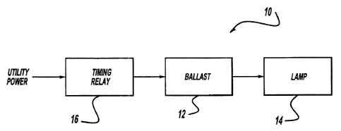
invention shown in more detail in Figure 2. Electrical assembly 10 includes a
ballast
12 adapted for electrical communication with a light source such as a High
Intensity
Discharge (HID) lamp 14. Electrical assembly 10 further includes an automatic
relay
device 16 which is provided in electrical communication with ballast 12 and is
adapted to receive power from a power source such as utility feed 18.
In keeping with the invention, relay device 16 is placed in each
luminaire of array 20 to cycle the lamp 14 off and back on so as to fulfill
the lamp
manufacturer's requirements and recommendations. Relay 16 is typically, but
not
necessarily, serially connected (back-to-back) SCRs (not shown). In a
preferred
embodiment, relay device 16 is designed to have predetermined random cycling
on-periods ranging from approximately 100 to 500 hours or any other suitable
cycling time. At these random intervals, the relay 16 interrupts power to the
ballast
12 thereby extinguishing the HID lamp 14. Power may be restored within a
predetermined period of time such as, for example, one minute. Because of the
characteristics of the high wattage lamp and, in particular, the HID lamp
illustrated,
-4-
CA 02345447 2001-03-26
WO 00/72639 PCT/US00/13558
it will not re-ignite until the arc has cooled to the point that the ballast
voltage can
break down the associated internal gasses. As those skilled in the art will
recognize,
this process can range anywhere from 4-15 minutes or longer depending upon the
specific luminaire dcaign. This cool-down period thus fulfills the lamp
manufacturer's cycling requirements and recommendations so as to minimize, if
not
eliminate, non-passive failures without the owner's intervention. In any case,
the
"off" time can be set to meet the requirements of the lamp manufacturer.
Electric;~l assembly 10 of the present invention is adapted to control
each associated luminaire individually. Relay 16 is therefore designed to have
a wide
range of random cycling times that vary with each device. This will ensure
that
multiple luminaires wily not be interrupted at the same time thus minimizing
localized
reduced illumination problems. While it is, of course, possible that more than
one
luminaire in an array 20 may be off at the same time, the probability is low
that
adjacent luminaires such as luminaires 22 and 24, 26 and 28, or 30 and 32,
etc. will
have overlapping interruption. If even the low probability of overlapping
interruption periods is of concern, an alternative embodiment is disclosed
herein
wherein a variety of relays may be used in an associated luminaire array each
having
more precise timing intervals of different values. In this manner, luminaires
using
relays of the same time interval may be located in an application such that
the outage
time may be coordinated with the operation of the facility .
The mixture of timing intervals will ensure that an entire section of an
array will not have overlapping interruption periods. Moreover, the precise
interval
of this approach will allow owners and users to predict with specificity when
power
interruptions will occur. While, of course, functional, this alternative
embodiment
will require substantial additional design and labor so as to ensure that
luminaires are
installed in compliance with an associated outage pattern. While such
attention to
detail in the installation of general lighting equipment is not the norm, it
may, of
course, be required depending upon the desired application.
In keeping with the invention, relay device 16 may also be
programmable to achieve the desired outage pattern or patterns. For example,
relay
-5-
CA 02345447 2001-03-26
WO 00/72639 PCTNS00/13558
16 may be designed to have different (predetermined) or random future turn off
times
and durations. That is, it randomizes or is pre-set for its next turn off time
and/or
duration following each turn off event.
If overlapping interruption is not a concern but desired, electrical
assembiy 10 of the present invention can, of course, be adapted to control
groups of
luminaires in array 20. In this manner, relay 16 will be provided in
electrical
communication with a plurality of luminaires such as luminaires 22-28.
With reference to Figure 3, there is shown a schematic of an
alternative embodiment of the present invention wherein the relay device is
configured to directly short the lamp. As shown, relay 16' is connected in
parallel
with secondary coil 34 of ballast 12' so as to short lamp 14' . This
arrangement
would typically find application in HID circuits where the secondary coil 34
of
ballast 12' is current limited. In such cases, the current handled by the
relay device
16' will thus be less than in the above embodiment wherein relay 16 is used to
control the primary coil of the ballast.
The benefit of this alternative embodiment is that the relay 16' is
normally "off" in this configuration, and only handles current for a limited
period of
time, approximately 1_'i minutes each week. When the relay 16 is in the
primary of
the ballast, it is essentially "on" all the time. Since the relay 16' is off
most of the
time, it will run cool resulting in improved reliability.
A second benefit derives from the failure modes of this type of device.
Solid state relays are most suitable for this type of switching (because of
cost reasons
related to the need for random timing), and attention must be paid to their
failure
mode. The power output stage of a solid state relay are back-to-back SCRs, and
they
normally fail in a shorted manner. In most cases, the relay device 16 will
stop
conducting for one direction of the AC power, resulting in a half wave
rectification
condition. For a transformer, this causes high currents that would probably
cause
a fuse to blow. This is a desirable result, since it would indicate to the
user that the
relay had failed and needs maintenance.
-6-
CA 02345447 2001-03-26
WO 00/72639 PCT/US00/13558
Howevf:r, in some instances both SCRs may fail shorted, which would
allow the ballast to operate normally. For a device that is to turn off
luminaires to
avoid permanent "on" situations, a failure mode where the relay keeps the
ballast
"on" is not entirely desirable. With the relay shorting out the lamp, as in
the
alternative embodiment, either failure mode (one or both SCR failures) would
force
the lamp to go out and indicate maintenance is required.
Still further, there is another benefit of the relay device 16' being in
the secondary 34 of the ballast 12' . Since the relay 16' requires a power
source to
operate, the configuration where the relay 16 is in the primary requires a
wide range
of operating voltages to be compatible with utility voltages of 120 to 480
volts.
Since the secondary o~f the ballast has a much more consistent voltage present
(especially across the range of HID lamps), the relay 16' may be designed for
a more
narrow-range of power voltages.
For those lamps that require a pulse to ignite the lamp, the relay I6'
will "see" the pulses across its output during lamp starting. These 2,000 to
4,000
volt pulses must be addlressed in the relay design through the use of snubbers
{not
shown) or other suitable voltage limiting devices.
While embodiments of the invention have been illustrated and
described, it is not intended that these embodiments illustrate and describe
all
possible forms of the invention. Rather. the wordy used 1n the cnerifiratinn
o~E.
words of description rather than limitation, and it is understood that various
changes
may be made without departing from the spirit and scope of the invention.