Note: Descriptions are shown in the official language in which they were submitted.
CA 02345608 2001-03-27
WO 00/19955 PC'T/US99I22167
ABSORBENT ARTICLE HAVING INTEGRAL WICKING BARRIERS
Background of the Invention
To prevent leakage of body exudates from absorbent articles such as feminine
care pads or napkins and disposable diapers, it is desirable that the exudates
not reach
the edges of the absorbent material in the article. A "center fill" strategy
is desirable for
leakage control, wherein fluids are preferentially held in a central region of
the article.
Further, absorbent articles with center fill strategies are desirable for the
clean
appearance they offer and the reduced wetted area in contact with skin.
Unfortunately, in
traditional absorbent articles, there is generally no barrier to bulk flow or
capillary wicking
from the target region to the edges of the article.
Efforts to prevent leakage from the sides of absorbent articles include using
fluid
impervious cuffs and flaps. These added barriers are costly and do not prevent
fluid from
reaching the edge of the absorbent article, though they can be effective in
reducing
leakage in some absorbent articles.
Central meltblown strips and other narrow strips of absorbent material have
been
added to the body side of absorbent articles to promote center filling of the
articles.
However, meltblown strips interfere with absorption of fluid into the
absorbent cellulosic
portions of the article and can hold wet fluid near the skin. Other efforts at
controlling fluid
intake to promote central filling have used narrow strips of cellulosic ar
other absorbent
material with a horizontal barrier between the strip and the underlying
absorbent core.
The horizontal barrier material for delaying wicking provides vertical
isolation of the central
strip from the absorbent core, but does not prevent flow out of the sides of
the wetted strip
or toward the sides of the article. Further, the horizontal fluid barrier
often occupies a
significant portion of the article's surface area and can result in
ineffective use of the
underlying absorbent core.
Embossing has also been used to promote longitudinal fluid flow, but
embossments generally are not successful in preventing lateral wicking and in
promoting
true center fill. Furthermore, heavy embossing can be an ineffective use of
absorbent
material since the embossed regions are typically highly densified, generally
having little
pore volume for absorption of fluid.
Longitudinal chambers have also been used wherein each channel or chamber of
absorbent material is completely isolated from the next by means of impervious
or flow
-- 1 --
CA 02345608 2001-03-27
WO 00/19955 PCT/US99/22167
restricting walls. In some cases, however, isolated chambers represent a poor
use of
absorbent material as one chamber may become overloaded and overflow onto the
cover,
resulting in smearing and inefficient use of the absorbent material in other
chambers.
Successful use of isolated chambers requires improvements for prevention of
chamber
overflow, prevention of undesirable surface transport and smearing, and
improved use of
the absorbent material in the absorbent article. Further, prior attempts at
isolated flow
chambers are generally complex in execution, costly, and may suffer from poor
product
integrity. Improved approaches are needed that can be mass produced for low
cost while
achieving high levels of performance.
In general, what is needed is an improved means for promoting center fill and
reducing flow toward the edges of the absorbent article for leakage reduction
that offers
improved feel and appearance of the article while also reducing smearing or
other forms
of failure.
Summar~of the Invention
In one aspect, the present invention resides in an absorbent article having a
longitudinal direction, a transverse direction, a vertical direction
substantially normal to
both the longitudinal and transverse directions, and a body side, the
absorbent article
comprising:
a) an absorbent core having a body side surface, the core comprising an outer
absorbent member having a central void open toward the body side of the
absorbent article, and a central absorbent member disposed over the central
void of the outer absorbent member and extending into the void; and
b) a wicking barrier disposed between the outer absorbent member and the
central absorbent member, the wicking barrier comprising a vertical component
and a horizontal component, the vertical component spanning a vertical
distance between the outer absorbent member and the central absorbent
member, and the horizontal component spanning a horizontal distance on the
body side surface of the absorbent core.
In another aspect, the invention resides in an absorbent article having a body
side,
the absorbent article comprising an absorbent core having a body-side surface
and
comprising an outer absorbent member and a central absorbent member having a
perimeter, and a wicking barrier spanning a vertical distance disposed along
at least a
portion of the perimeter of the central absorbent member, the wicking barrier
also
__ 2 __
CA 02345608 2001-03-27
WO 00/19955 PCT/US99/22167
comprising a horizontal component residing on the body-side surface of the
absorbent
core.
In another aspect, the invention resides in an absorbent article having a
longitudinal direction, a transverse direction, and a vertical direction
substantially normal
to both the longitudinal and transverse directions, a crotch region, and a
body side, the
absorbent article comprising:
a) an absorbent core having a body side surface, the absorbent core comprising
a central absorbent member surrounded by a outer shaping member with a
central void for receiving the central absorbent member;
b) a baffle layer beneath the central absorbent member; and
c) a wicking barrier disposed between the outer shaping member and the central
absorbent member, the wicking barrier comprising a vertical component and a
horizontal component, and the horizontal component spanning a horizontal
distance on the body side surface of the outer shaping member.
In another aspect, the invention resides in an absorbent article with a
longitudinal
direction, a transverse direction, a vertical direction substantially normal
to both the
longitudinal and transverse directions, a body side, and a garment side, the
absorbent
article comprising:
a} an absorbent core having a central absorbent member and an outer absorbent
member, the outer absorbent member having a central void defined therein for
receiving at least a portion of the central absorbent member, whereby an
interface is defined between the central absorbent member and the outer
absorbent member; and
b) a wicking barrier, desirably a single-ply wicking barrier, disposed along
the
interface between the central absorbent member and the outer absorbent
member, the wicking barrier spanning a vertical distance in the absorbent
article and having a variable liquid permeability such that the liquid
permeability
of the wicking barrier is lower near the body side and higher near the garment
side.
The wicking barrier can extend downward from the surface of the absorbent core
to span a vertical distance less than the vertical distance of the interface,
or, alternatively,
can extend substantially along the entire vertical distance of the interface
and is provided
with apertures or openings away from the body side of the absorbent core such
that fluid
passing through the wicking barrier must follow an elongated or tortuous path
to pass out
of the central absorbent member. The wicking barrier can also be provided with
a
__ 3 __
CA 02345608 2001-03-27
WO 00/19955 PCT/US99/22167
horizontal component on or near the surface of the absorbent core spanning a
horizontal
distance to reduce the likelihood of contact between the outer absorbent
member and the
central absorbent member when the article is laterally compressed or bunched
together in
use.
In another aspect, the invention resides in an absorbent article with a crotch
region, a longitudinal direction, a transverse direction, and a vertical
direction substantially
normal to both the longitudinal and transverse directions, the absorbent
article comprising:
a) an absorbent core having a central absorbent member and an outer shaping
member, the outer shaping member having a central void defined therein for
receiving at least a portion of the central absorbent member, whereby an
interface is defined between the central absorbent member and the outer
shaping member, the interface spanning a vertical distance, the outer shaping
member suitably having a thickness of at least about 1 mm, an edge width of
at least about 2 mm, and a basis weight of at least about 100 gsm; and
b) a wicking barrier disposed along the interface between the central
absorbent
member and the outer absorbent member.
In another aspect, the invention resides in an absorbent article comprising an
absorbent core comprising an outer absorbent member and a central absorbent
member,
the outer absorbent member having a central void therein for receiving an
insert, and the
central absorbent member being inserted into the central void, and a wicking
barrier
between the outer absorbent member and the central absorbent member, the
wicking
barrier spanning a vertical distance that can be substantially as great as the
thickness of
the central absorbent member or can be less than the thickness of the central
absorbent
member. The central void can be a hole that passes completely through the
outer
absorbent member, or can be a depressed region within a contiguous,
uninterrupted outer
absorbent member. Desirably, the wicking barrier comprises a horizontal
component that
serves as a ledge on the surface of the absorbent core. In one embodiment, the
central
void longitudinally divides the outer absorbent member into two discontiguous
sections. In
other embodiments, the outer absorbent member is divided by the central void
in the
crotch region, but the outer absorbent member may be contiguous in the front
or back
portions of the article (i.e., the central void does not extend substantially
beyond the
crotch region).
In another aspect, the present invention resides in an absorbent article
comprising
a composite absorbent core having a center, the absorbent core having a body
side
surface and comprising a central absorbent member and a surrounding outer
absorbent
__ 4 __
CA 02345608 2001-03-27
WO 00/19955 PCT/US99/22167
member, wherein a plurality of vertically oriented segments of hydrophobic
material in the
central absorbent member define liquid wicking pathways from the center of the
central
absorbent member to the outer absorbent member.
In another aspect, the invention resides in an absorbent article comprising a
backsheet and a concentric absorbent structure attached to the backsheet, the
concentric
absorbent structure having a thickness and comprising multiple alternating
concentric
layers of barrier material and absorbent material, wherein the barrier
material substantially
spans the thickness of the concentric absorbent structure.
In another aspect, the invention resides in a method for producing an
absorbent
article having a central absorbent member, the method comprising:
a) preparing an outer absorbent member, wherein the outer absorbent member
has a central void;
b) deposing a Payer of a flexible barrier material over the central void; and
c) inserting a section of absorbent material into the central void and over
the
barrier material to form a central absorbent member, such that a portion of
the
barrier material separates the central absorbent member from the outer
absorbent member along a vertical distance.
The above method may further comprise deposing a backsheet beneath the
absorbent core; deposing a topsheet above the absorbent core; and attaching a
portion of
the topsheet to a portion of the backsheet.
In another aspect, the invention resides in a method for producing an
absorbent
article having a central absorbent member, a garment side, and a body side,
the method
comprising:
a) preparing an outer shaping member having a first portion and a second
portion
with a central void between the first portion and the second portion, wherein
the central void has a vertical depth and the outer shaping member has a
surface comprising a wicking barrier that spans at least a portion of the
vertical
depth of the central void; and
b) inserting an absorbent material into the central void of the outer shaping
member to form a central absorbent member.
In yet another aspect, the invention resides in a method of preparing an
absorbent
article comprising a concentric absorbent structure with multiple vertical
wicking barriers
interposed between layers of absorbent material, the method comprising:
a) superposing at least one layer of a barrier material onto at least one
layer of
absorbent material to form a multilayered structure;
__ 5 __
CA 02345608 2001-03-27
WO 00/19955 PCTNS99/22167
b) rolling the multilayered structure about a rolling axis to form a spiral
wound roll;
c) slicing a portion of the spiral wound roll substantially normal to the
rolling axis
to form a substantially concentric absorbent structure; and
d) attaching the substantially concentric absorbent structure to a backsheet.
Brief Description of the Drawin4s
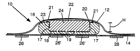
FIG. 1A and 1B depict a cross-section of a sanitary napkin of the present
invention.
FIG. 2 depicts a cross-section of a sanitary napkin of the present invention
having
two absorbent components in the central absorbent member.
FIG. 3A and 3B depict a cross-section of a sanitary napkin of the present
invention
having three absorbent components in the central absorbent member.
FIG. 4A and 4B depict a cross-section of a sanitary napkin of the present
invention
having a contoured central absorbent member.
FIG. 5A and 5B show a diaper having a central absorbent member surrounded by
a moat.
FIG. 6 depicts a cross-section of a sanitary napkin wherein barrier material
is
wrapped around the upper surface of the central absorbent member.
FIG. 7A and 7B and 7C depict a cross-section of an absorbent article with a
central absorbent member and an outer absorbent member, with a wicking barrier
that
does not pass beneath the central absorbent member.
FIG. 8 is a top view of a sanitary napkin having a central absorbent member
concentrically surrounded by an outer absorbent member.
FIG. 9 is a top view of a sanitary napkin having a central absorbent member
separated from the outer absorbent member by longitudinal barrier zones.
FIG. 10 is a top view of a sanitary napkin comprising a spiral wound composite
with barrier material between successive layers.
FIG. 11 shows a layer of a spiral wound composite.
FIG. 12 shows a spiral wound roll from which a spiral wound composite is cut.
FIG. 13 shows a length of heterogeneous barrier material having multiple
permeability or wicking zones for use in a spiral wound composite.
FIG. 14 shows a feminine care pad with wings having a shaped spiral wound
composite layer.
__g__
CA 02345608 2001-03-27
WO 00/19955 PCTNS99/22167
FIG. 15 shows a top view of a sanitary napkin with multiple wicking barriers
arranged to provide a labyrinth-like tortuous pathway for radially outward
wicking from the
target area of the central absorbent member.
FIG. 16A and 16B show a cross-section of an absorbent article according to the
present invention wherein the central absorbent member can expand
substantially when
wetted.
FIG. 17 shows a cross-section of an absorbent article according to the present
invention wherein the central absorbent member comprises multiple longitudinal
bands of
absorbent material for improved wicking in the longitudinal direction.
FIG. 18A and 18B show cross-sections of an absorbent article comprising a
protruding loop of cover material to form a runoff barrier near the periphery
of the central
absorbent member.
FIG. 19A and 19B show cross-sections of an absorbent article comprising
multiple
protruding loops of cover material to form runoff barriers an the body-side
surface.
FIG. 20A and 20B show two exemplary forms of loops of cover material having
multiple folds.
FIG. 21 shows the top view of several sanitary napkins described in the
Examples,
also showing embossed lines.
FIG. 22A and 22B depict an absorbent article with two layers of film serving
as the
wicking barrier.
FIG. 23 depicts an absorbent article with two layers of film serving as the
wicking
barrier, wherein the outer absorbent member is largely encased in impervious
material.
FIG. 24A and 24B depict an absorbent article with a single wicking barrier
extending to the longitudinal sides of the absorbent core in the crotch
region.
FIG. 25A and 25B depict embodiments in which the central absorbent member
comprises an absorbent layer wrapped around a second layer of absorbent
material.
FIG. 26 depicts an absorbent article in which the topsheet wraps the edges and
undersides of the outer absorbent member to permit the outer edges of the
absorbent
core to flex away from the backsheet.
FIG. 27 depicts an embodiment similar to FIG. 26 in which the topsheet further
wraps the edges and underside of the central absorbent member to permit its
edges to
flex away from the backsheet.
FIG. 28 depicts a cross-section of an absorbent article wherein the wicking
barrier
wraps around the outer absorbent member and runs along the garment side of the
article,
serving as a backsheet.
__7_-
CA 02345608 2001-03-27
WO 00/19955 PCTNS99122167
FIG. 29 depicts a cross-section of an absorbent article having a unitary
shaping
member surrounding a central absorbent member.
FIG. 30 depicts a commercial maxipad.
FIG. 31 depicts the modified maxipad of FIG. 30 after a wicking barrier has
been
added according to the present invention.
FIG. 32 depicts a transverse cross-section of a sanitary napkin according to
the
present invention.
Detailed Description of the Invention
To fully achieve a center-fill effect for fluid in an absorbent article such
as a
sanitary napkin or diaper, it has been discovered that excellent results are
obtained when
a central absorbent member is properly isolated from a surrounding outer
absorbent
member of the article, such that fluid communication between the absorbent
members is
reduced, impeded, or prevented. The isolation can be achieved with barrier
material
spanning a vertical distance between a central absorbent member and a
surrounding
outer absorbent member to interfere with wicking of fluid (or other forms of
flow) from the
center of the absorbent article toward the edges of the article.
Alternatively, the outer
absorbent member may be replaced with a resilient outer shaping member that
need not
be absorbent. Further, the barrier material desirably can also span a
horizontal distance
on the surface of the absorbent core of the article for reduced leakage and
improved
control of fluid flow. The horizontal component of the wicking barrier serves
as a ledge on
the absorbent core with multiple desirable functions, hereafter described.
The vertical wicking barriers isolate absorbent members of the absorbent core
for
reduced leakage to the side without the disadvantage offered by horizontal
barriers or
horizontal transfer delay layers of making absorbent material in the center of
the article
less accessible to incoming flow. Specifically, the wicking barriers isolate
or partially
isolate a central absorbent member from the surrounding portions of an outer
absorbent
member such that in-plane or lateral wicking of fluid is impaired, and thus
can be termed
"wicking barriers to lateral flow." The term "lateral," as used herein, refers
to the in-plane
flow directions in an absorbent article, particularly the direction of flow
from the central
portions of an absorbent core toward the outer edges of the article,
particularly the
longitudinal edges. More specifically, in-plane flow from the center to the
outer regions of
an absorbent core can be termed "radially outward flow." The use of vertical
wicking
barriers permits any desired portions of the body side surface of each
absorbent
__ g __
CA 02345608 2001-03-27
WO 00/19955 PCT/US99/22167
component to remain available for fluid intake and generally provides for more
efficient
use of absorbent material.
In most embodiments of the present invention, the flow isolating effect within
the
absorbent core is achieved at least in part because the wicking barrier spans
a vertical
distance between the central absorbent member and the surrounding portion of
the
absorbent core (i.e., the outer absorbent member, which may surround the
entire central
absorbent member or only surround its edges in the crotch region or other
region where
lateral leakage is likely), thus giving a vertical component to the barrier.
Therefore, the
barriers can also be termed "vertical wicking barriers" due to the vertical
component of the
geometry. The vertical component of the wicking barrier spans a vertical
distance that is
desirably of at least about 20 percent, more desirably of at least about 50
percent, suitably
of at least about 70 percent, and up to about 100 percent of the average
thickness of the
central absorbent member.
The central absorbent member can lie within a depression or void within a
surrounding outer absorbent member or can lie substantially above the outer
absorbent
member and can also serve as the primary absorbent material of the absorbent
article. It
has also been discovered that isolation of a central absorbent member can be
achieved
without promoting overflow of liquid entering the central absorbent member due
to
excessive saturation and without promoting surface smearing. This can be
achieved by
providing tortuous pathways for fluid flow from the target area to the
surrounding
absorbent material, thus permitting fluid to move toward the outer absorbent
member
when the absorbent capacity of the central absorbent member is approached, but
whereby such radially outward flow is delayed or impeded by the tortuous
pathways.
Wicking barriers with vertical components establish the tortuous or labyrinth-
like flaw
pathways by which fluid in the center of an absorbent core can gradually move
toward the
outer absorbent member of the pad in a way that reduces leakage and enhances
utilization of the absorbent material.
In one class of related embodiments, the wicking barrier does not completely
separate the adjacent zones of absorbent material but prevents radially
outward flow (flow
from the center of the pad to the edges, especially the longitudinal edges of
the article) in
the upper regions of the absorbent zones near the user's body, while
permitting some
degree of radially outward flow through tortuous pathways or labyrinth-like
pathways,
preferably pathways remote from the body side or upper surface of the
absorbent core,
such that the outer absorbent member or regions of the article can serve a
useful
absorbent function, such as providing a source of additional absorbent
capacity when the
main absorbent capacity of the central absorbent member is exceeded, or
serving as an
__ g __
CA 02345608 2001-03-27
WO 00/19955 PCTNS99/22167
indicator that the article should be replaced. For example, a wicking barrier
comprising an
impervious film may form a wall around a central absorbent insert placed
within a hole in
an outer absorbent member, but still permit some radially outward flow away
from the
body side surface if the lower portions of the film away from the body side
surface are
provided with apertures through which fluid can flow when the central
absorbent member
becomes saturated.
While the wicking barriers can interfere with wicking flow, wherein capillary
forces
move the fluid, the wicking barriers naturally can impede more rapid flow as
well, including
gushes of flow driven by hydraulic pressure or gravitational force. Thus, the
flow isolation
effect of the wicking barrier is not limited to wicking flow alone.
One problem known with previous attempts at isolating longitudinal chambers of
absorbent material has been surface smearing of the fluid, typically due to a
single
isolated chamber becoming saturated with fluid and then forcing additional
fluid to flow
along the surface of the article to other chambers or to the edges of the
article. If the
primary fluid pathway from one absorbent region or member to the next is along
the
surface of the article, smearing is likely. Likewise, complete isolation of an
absorbent
member can keep that member wet and provide discomfort to the user and result
in
inefficient use of the absorbent material of the article. Accordingly, surface
smearing and
oversaturation of the target region of the absorbent article can be reduced by
any or all of
the following: 1 ) redistributing the mass and/or the absorbent capacity in
the absorbent
article such that the central absorbent member has substantially greater basis
weight
and/or absorbent capacity than the outer absorbent member of the absorbent
article, and
desirably also has a greater thickness to ensure preferential contact of fluid
with the
central absorbent member; 2) providing flow pathways from the central
absorbent
member to the surrounding or adjacent outer absorbent member or regions that
are
remote from the surface of the absorbent article such that fluid flow from one
member to
the next is possible by a route other than along the surface, such as by
openings in the
wicking barrier away from the upper surface of the article, and desirably by a
tortuous
route that delays lateral wicking enough for effective center fill without
promoting overflow
or oversaturation; 3) providing a horizontal component to the barrier material
such that a
portion of the barrier material resides on the surface of the absorbent core
in addition to
the portion spanning a vertical distance between adjacent absorbent members,
thus
forming "ledges" of barrier material near the surface of the absorbent article
(desirably
beneath the cover but above the absorbent core).
The development of vertical wicking barriers with horizontal components on the
body-side surface of the absorbent core of an absorbent article is believed to
offer many
-- 10 --
CA 02345608 2001-03-27
WO 00119955 PCT/US99/22167
advantages previously unavailable in absorbent articles. First, the horizontal
component is
especially effective in preventing wicking contact between the central
absorbent member
and the adjacent outer absorbent member. If a vertical barrier ends abruptly
at the surface
between two adjacent chambers, there is the possibility that wicking contact
between the
two chambers will be established at the upper surface of the article,
especially if the article
is laterally compressed or bunched together in use or if the article
experiences in-plane
shear that can move the upper layers of one absorbent member toward other
absorbent
members in the absorbent article. Even a small region of contact between
adjacent
absorbent members can result in undesired lateral wicking, and since the fluid
flow
between the two members in that case will be primarily along the surface,
surface
smearing is a possibility. A horizontal component, or ledge, at the top of the
vertical
wicking barrier can greatly increase the effectiveness of the wicking barrier
and isolate the
upper regions of the adjacent absorbent members, thus reducing the chances of
surface
smearing and preventing undesired flow toward the edges of the article, from
whence the
fluid may leak and soil the wearer's clothes.
Second, the ledge can redirect flow toward the central absorbent member,
increase the center-fill effect, and increase the effective size of the
central absorbent
member. Particularly desirable is a hydrophobic ledge around or along the
central
absorbent member extending away from the central absorbent member and toward
the
edges of the article, spanning a short horizontal distance, and preferably a
distance
approximately equal to a characteristic drop size of the fluid being absorbed.
For many
absorbent articles, the horizontal distance spanned is desirably between about
0.3 millimeters (mm} and about 5 mm, and specifically between about 0.5 mm and
about
3 mm, more specifically between about 1 mm and about 2.5 mm, and alternatively
between about 0.2 mm and about 2 mm. When fluid is deposited on such a ledge,
the
fluid can be redirected toward the central absorbent member instead of flowing
into the
underlying outer absorbent member. Desirably, the ledge lies on the outer
absorbent
member and helps redirect fluid toward the central absorbent member. This is
especially
effective when the central absorbent member is more elevated than the outer
absorbent
member, so that fluid on the ledge is likely to contact the elevated, adjacent
central
absorbent member. However, in one embodiment, the ledge can extend
substantially all
the way to the longitudinal edges of the crotch region of the outer absorbent
member. In a
related embodiment, the ledge can substantially cover all of the body side
surface of the
outer absorbent member outside the perimeter of the central absorbent member.
This is
particularly helpful when the central absorbent member is sufficiently sized
and placed to
receive essentially all of the liquid received by the absorbent article so
essentially none
-- 11 --
CA 02345608 2001-03-27
WO 00/19955 PCT/US99/22167
falls on the ledge. In this manner, the ledge can provide excellent wicking
isolation of the
central absorbent member from the outer absorbent member even under extreme
bunching of the article during dynamic use.
Third, the ledge can provide increased stability, strength, and resiliency to
an
absorbent article. This is particularly so when the ledge is adhesively or
otherwise
attached to the cover or topsheet of an absorbent article andlor to one or
more elements
of the absorbent core. A problem in some previous attempts at providing
isolated
chambers in an absorbent article is that a film or other barrier between
adjacent chambers
eliminates the fiber-fiber bonding or entanglement between fibers that holds
an absorbent
core together, resulting in an absorbent core which can come apart, separate,
or fail either
in tension or compression or during bending. In the present invention, the
ledge of the
wicking barrier is easily attached to the cover and can further be attached to
either or both
of the central absorbent member and the outer absorbent member adhesively, by
thermal
or ultrasonic bonds, or by other attachment means known to one skilled in the
art. By
geometric considerations alone, a wicking barrier with a ledge can effectively
hold the
central absorbent member in place between the wicking barrier and the cover
when the
ledge is attached to the cover or to the surface of the outer absorbent
member.
Fourth, the ledge of the wicking barrier can serve important visual roles. It
can help
the wearer with proper placement by clearly marking the intended target zone,
particularly
if the wicking barrier has a color such as pink or blue that contrasts well
with the
absorbent material of the core. It can provide an important visual cue to the
user that a
central absorbent member exists and that the article provides a center fill
strategy. The
visible "protection zone" can increase user confidence in the article and can
provide an
improved clean appearance to the article, even after use. Further, if the
(edge is at least
somewhat opaque, it can mask incipient lateral flow from the central absorbent
member to
the outer absorbent member. Thus, a desirable wicking barrier material can be
a thin,
flexible polyolefin film or nonwoven layer, such as a web having a basis
weight less than
40 grams per square meter (gsm) and desirably less than 25 gsm, optionally
comprising
coloring agents and desirably comprising pigments ar fillers such as titanium
dioxide or
calcium carbonate for opacity.
In addition, surface smearing can be reduced with the use of a cover material
that
is especially well suited for the vertical barriers and vertical barriers with
horizontal
components of the present invention. Such a cover material comprises an
inherently
hydrophilic basesheet with a three-dimensional topography, further comprising
hydrophobic matter deposited on the uppermost portions of the basesheet. Such
covers
are disclosed in the commonly owned copending US patent application, Ser.
__ 12 __
CA 02345608 2001-03-27
WO 00/19955 PCTNS99/22167
No. 08/997,287, "Dual-zoned Absorbent Webs," filed Dec. 22, 1997, by Chen et
al., herein
incorporated by reference in its entirety. A three-dimensional, wet resilient
tissue, for
example, with a crosslinked silicone material on the uppermost regions of the
surface, can
provide an excellent dry feel while permitting good fluid entry into an
absorbent
basesheet. If the upper region of the underlying central absorbent member
comprises a
densified airlaid strip or other material having higher capillary pressure
than the
hydrophilic basesheet of a dual-zoned cover, then fluid can be pulled
effectively from the
basesheet of the cover into the absorbent core, resulting in small stain sizes
and
exceptionally dry feel.
Tortuous pathways from the central absorbent member to the outer absorbent
member can be provided in a variety of ways. A single layer of hydrophobic
barrier
material between the central absorbent member and the surrounding outer
absorbent
member can comprise small apertures, slits, or holes remote from the body side
of the
absorbent article such that fluid entering the central absorbent member must
travel
downward through a substantial portion of the thickness of the central
absorbent member
before having access to openings leading to absorbent material outside the
central
absorbent member. The apertures or flow openings desirably are not present in
the crotch
region of the article, but can be placed closer to the longitudinal ends of
the central
absorbent member such that wicking through the apertures only occurs after
fluid has
been wicked longitudinally in the central absorbent member toward its ends,
and then the
fluid will still be remote from the crotch region where leakage tends to be
more
problematic in most absorbent articles. More complex and tortuous pathways can
be
created through the use of barrier material arranged in a spiral design from
the central
portions of the absorbent article to the outer regions, such that fluid in the
center must
wick along a spiral path in the plane of the article to reach the outer
regions of the article.
Likewise, barrier material may be arranged to define a labyrinth-like pathway
from the
central portions of the article to the outer regions, such that in-plane
wicking can occur but
only along a complex route. Combinations of labyrinth-like pathways and
apertures or
openings in selected portions of the barrier material can be used.
The barrier material may be impervious or may be permeable to liquid or, in
one
embodiment, has a variable permeability, particularly a vertical gradient in
permeability
and/or porosity such that the lowest permeability or porosity of the barrier
material is
found near the body side of the absorbent core or the absorbent article and
the highest
permeability is near the garment side of the absorbent core or the absorbent
article, with
the permeability or porosity of the barrier material increasing with vertical
distance from
-- 13 --
CA 02345608 2001-03-27
WO 00/19955 PCTNS99/ZZ167
the body side to the garment side such that lateral flow is most strongly
hindered near the
body side and least hindered near the garment side.
Possible uses of the present invention include absorbent articles for intake,
distribution, and retention of human body fluids. Examples include feminine
care pads and
related catamenial devices or sanitary napkins, including "ultra-thin" pads
and pantiliners
and maxipads. Examples of ultra-thin sanitary napkins are disclosed in US Pat.
Nos. 4,950,264 and 5,009,653 issued to Osborn; and US Patent No. 5,649,916,
issued
July 22, 1997 to DiPalma et al., each of which are herein incorporated by
reference in
their entireties. Likewise, the present invention can be applied to diapers,
disposable
training pants, other disposable garments such as swimming garments,
incontinence
articles, bed pads, sweat absorbing pads, shoe pads, bandages, helmet liners,
wipes and
wipers, or other absorbent articles. The present invention can also be
incorporated in
articles adapted for particular portions of garments to be worn on the human
body,
gaskets for ostomy bags, and medical absorbents and wound dressings. The
articles of
the present invention provide significant leakage protection, fluid center-
fill absorptive
performance, and other desirable attributes for absorbent articles.
For feminine care pads in particular, the present invention offers surprising
advantages in terms of comfort and fit. When the central absorbent member and
the outer
absorbent member are physically separate members, the transverse compressive
stiffness of the article is greatly reduced. In other words, the article can
bend between the
user's thighs more easily and feels less stiff. Placing longitudinal slits in
the central
absorbent member is also helpful in reducing transverse stiffness. Further,
the presence
of a wicking barrier between the two absorbent members can enhance the ability
of one
absorbent member to move relative to another, as by sliding along the wicking
barrier
during transverse compression, especially if the wicking barrier is not
adhesively attached
to both absorbent members across the wicking barrier's entire surface, or if
the wicking
barrier is adhesively attached to no more than one absorbent member. Thus, the
wicking
barrier can provide additional freedom of movement and freedom of deformation
to the
absorbent members for reduced stiffness and better body fit. The presence of a
wicking
barrier with a vertical component in the crotch region, which separates the
central
absorbent member and outer absorbent member and allows folding or motion
therebetween, appears especially useful in promoting a W-shape geometry of
sanitary
napkins when compressed in use which can rise toward the body for better
intake of fluid
and better fit in general. Further still, the center-fill strategy made
possible by the present
invention can be used to generally ensure that the outer absorbent member
remains dry
-- 14 --
CA 02345608 2001-03-27
WO 00/19955 PC'T/US99/Z2167
under typical usage conditions, which in turn allows the outer absorbent
member to better
maintain its shape and to help hold the pad in a comfortable and effective
position.
Indeed, recognizing that the primary absorbent material in the central
absorbent
member can provide substantially all of the absorbent capacity needed for many
absorbent articles such as a feminine care pad (typically 7 milliliters (ml)
of fluid will be
absorbed, with a high end of about 15 ml), the outer absorbent member can be
used to
achieve several important functions other than absorbency. Either as a ring of
material
around the central absorbent member or as a pair of longitudinal bands
surrounding the
central absorbent member longitudinally, the outer member helps define the
shape of the
article, particularly when attached adequately to the wearer's panties. In
conventional
sanitary napkins, the article can become excessively bunched or compressed
when
wetted, but by maintaining the outer absorbent member in a dry state, it can
maintain its
shaping and body fit functions throughout use. Thus, the outer absorbent
member can
serve as a shaping and body fit element as well as a "cradle" to hold the
central absorbent
member and the wicking barrier in place. In fact, these functions can be
achieved whether
the outer member is absorbent or not, though it is desirable that the outer
member be
absorbent to take up fluid that might not be successfully held by the central
absorbent
member. Nevertheless, in one embodiment of an absorbent article such as a
feminine
care pad designed to maintain good body fit and provide leakage protection,
the outer
member need not be absorbent at all but can be a flexible frame member capable
of
holding the wicking barrier and central absorbent member in place. Thus, an
outer
shaping member can be used instead of an outer absorbent member, though it is
preferred that the outer member be absorbent.
The shaping member can be porous, such as a ring of a polyurethane foam; a
polyethylene foam such as the product known as VOLARAT"' 2a polyethylene foam,
obtained from Voltek Corp., of Lawrence, Mass.; or a foam rubber material
(e.g., foamed
styrene butadiene), foamed silicones, or foamed vinyl plastics. Several such
foams can be
obtained from Woodbridge Foam Fabricating, Inc., located in Chattanooga,
Tennessee,
from the E. N. Murray Company, Inc., located in Denver, Colorado, and Astro-
Valcour,
Inc., located in Glens Falls, New York. Foam materials desirably have a
density of about
0.02 grams per cubic centimeter (g/cc) to about 0.1 glcc. The foam material
desirably is
treated to be absorbent andlor hydrophilic, but need not be hydrophilic. In
the case of a
closed-cell foam or a foam with an impervious skin on the outer surface, the
surface of the
foam itself can serve as a wicking barrier having both a vertical component
and a
horizontal component on the bodyside surface of the shaping member. Thus; in
general,
the shaping member can comprise an integral wicking barrier or can have an
additional
-- 15 --
CA 02345608 2001-03-27
WO 00/19955 PCTNS99/22167
polymeric barrier provided on its surface, or can be separated from the
central absorbent
member by a separate layer of barrier material serving as a wicking barrier.
In one related embodiment, the wicking barrier and the outer shaping member
are
also integral with a backsheet and can be composed from a single piece of
impervious
material. The backsheet then also can serve as the baffle layer beneath the
central
absorbent member. For example, a single section of shaped flexible closed cell
foam,
desirably comprising an external impervious skin, can be shaped to provide a
thin central
layer under the central absorbent member, expanding away from the longitudinal
centerline to provide thicker regions outside the central absorbent member
that serve as
the outer portions of the outer shaping member. (The thin central portion is a
bridging
portion between the outer portions.) Since the central absorbent member is
contained by
the outer shaping member (within the central sides of the outer portions and
above the
underlying thin bridging region of the foam body), there is no need for an
additional
backsheet, assuming the foam is truly impervious or comprises an impervious
skin.
In general, for embodiments with an impervious or nonabsorbent outer shaping
member, a separate backsheet is not necessary. Nevertheless, some form of a
baffle
layer must exist beneath the central absorbent member to prevent leakage. If a
substantially liquid impervious outer shaping member is used and is
contiguous, e.g.,
comprises first and second outer portions joined by a relatively thin (thinner
than the outer
portions) bridging member, then the outer shaping member itself can serve as
the baffle
layer and can replace the function of a backsheet, if desired. If a complete
hole rather
than merely a depression exists in the central portion of the outer shaping
member for
receiving the central absorbent member, then a separate baffle layer must be
used. This
can be a liquid impervious backsheet, a portion of which serves as the baffle
layer
beneath the central absorbent member, or it can be the wicking barrier if it
runs beneath
the central absorbent member to prevent leakage of fluid toward the garment
side of the
article, or it can be a separate layer of impervious or hydrophobic material
such as a
flexible polymer film, including material integrally attached to the central
absorbent
member such as a thermoplastic flm, or an impervious coating or layer of
adhesive. In
any case, the construction of the article generally serves to isolate fluid in
the central
absorbent member for a true center-fill effect and prevent or reduce
substantial fluid
contact with the outer shaping member, while providing a conformable article
that can fit
against the body in use.
An outer shaping member comprising foam or other materials can be preshaped to
conform suitably to the body. Examples of materials and methods for preparing
conformable, resilient shaped members are disclosed in US Patent No.
5,591,150, issued
-- 16 -
CA 02345608 2001-03-27
WO 00/19955 PCT/US99/22167
Jan. 7, 1997 to Olsen et al., herein incorporated by reference in its
entirety. The outer
shaping member can comprise absorbent materials, particularly cellulose, such
as a
regenerated cellulose foam or stabilized fluff pulp or air laid wood fibers,
stabilized with
thermoplastic fibers, crosslinkers, or wet strength agents, and may be
preshaped or can
be planar. Desirably, the outer absorbent member comprises densified fluff
pulp,
stabilized air laid pulp, or the soft pulp sheets disclosed in US Patent No.
5,562,645,
issued Oct. 8, 1996 to Tanzer et al., herein incorporated by reference in its
entirety, and
desirably has a density less than 0.2 g/cc and more specifically less than 0.1
g/cc, and
most specifically less than 0.07 g/cc. Coform, a meltblown air-formed
combination of
meltblown polymers, such as polypropylene, and absorbent staple fibers, such
as
cellulose, can also be used. The outer shaping member can be a composite
element,
such as a layer of cellulosic fibers joined to a polymeric foam Layer. In one
embodiment,
the outer shaping member is extensible such that its size can be adjusted for
improved fit.
The outer shaping member can also be biodegradable and/or flushable, if
desired.
Further, the central absorbent member can be detachable to permit disposal and
replacement with a new central absorbent member, rather than discarding the
entire
article.
In one embodiment, the outer shaping member can comprise gas-filled bubbles
sealed inside polymeric material, such as air bubbles sealed between two
layers of a
polymeric film similar to a bubble wrap material commonly used for protection
of articles
during shipment. The gas-filled bubbles can be optimized in size and shape to
conform to
the body and provide shaping, cushioning, and gasketing functions, while
preventing
wicking from the central absorbent member. In such embodiments, the width of
the central
absorbent member desirably should be no more than 2 to 4 cm, and the shaping
member
should have a thickness of at least about 2 mm, desirably from about 2.5 mm to
7 mm,
with a width (distance from the edge of the outer absorbent member to the
outer
longitudinal side of the shaping member) of at least 1 mm and desirably at
least about
3 mm. The shaping member in such embodiments can comprise one or more gas-
filled
bubbles having a volume of at least about 0.2 cubic centimeters, desirably at
least about
0.5 cubic centimeters, and more desirably at least about 1 cubic centimeter.
As with the outer absorbent member, the outer shaping member desirably
promotes good body conformability. When used in sanitary napkins or feminine
pads, for
example, the outer shaping member desirably promotes a W-fold geometry in the
crotch
region when the pad is worn. Thus, the size, thickness, stiffness, and
geometry of the
outer shaping member should be adjusted to permit it to flex in use into a W-
fold when
combined with the other components of the absorbent article. Design principles
given
__ 17 __
CA 02345608 2001-03-27
WO 00/19955 PCTNS99/22167
herein for embodiments comprising an outer absorbent member can generally be
applied
to embodiments comprising an outer shaping member, in addition to explicit
teachings
herein for the outer shaping member.
For best comfort, the outer shaping member or outer absorbent member desirably
should be soft, resilient and easily compressible. The resiliency should be in
the range of
about 15 percent to about 60 percent rebound, preferably about 15 percent to
about 50
percent and more preferably about 15 percent to about 35 percent, as
determined by the
ASTM Test Method D3574-91 procedure H. Compressibility should be in the range
of
about 0.69 kPa (0.1 pounds per square inch (psi)) to about 13.8 kPa (2 psi) at
50% compression, preferably from about 2.1 kPa (0.3 psi) to about 11.7 kPa
(1.7 psi) at
50% compression and most preferably from about 3.45 kPa (0.5 psi) to about
10.3 kPa
(1.5 psi) at 50% compression, as determined by the ASTM Test Method D3574-91
procedure C.
Generally, the outer shaping member has a thickness of at least about 1 mm,
specifically at least about 2 mm, more specifically at least about 3 mm, and
most
specifically from about 3 mm to about 7 mm. Desirably, the average thickness
of the
shaping member is at least about 20 percent of the average thickness of the
central
absorbent member, and more specifically is at least about 30 percent of the
average
thickness of the central absorbent member. The thickness of the outer shaping
member
can also be greater than that of the central absorbent member. For example,
the average
thickness of the central absorbent member can lower by at least about 20
percent or at
least about 50 percent than the average thickness of the outer shaping member.
The "edge width" of the outer shaping member, defined herein as the lateral
distance along a continuous portion of the outer shaping member along the
transverse
centerline, specifically from the inner edge (adjacent the central absorbent
member) of the
outer shaping member to the outer edge thereof, is desirably at least about 2
mm and
specifically at least about 3 mm, more specifically at least about 4 mm. For
example, a
7 cm wide rectangular foam section with a 5 cm wide central depression therein
for
receiving a central absorbent member would have an edge width of 1 cm.
In a preferred embodiment, the outer shaping member is also an outer absorbent
member comprising cellulosic fibers, the outer absorbent member being
substantially
surrounded by impervious material (e.g., the wicking barrier and the
backsheet) such that
the absorbent material remains substantially dry in use. In one embodiment,
the wicking
barrier completely covers the body-side surface of the outer absorbent member
and forms
a seal with the backsheet in the region between the outer absorbent member and
the
central absorbent member and, optionally, is attached to the backsheet
adjacent the outer
__ 1 g __
CA 02345608 2001-03-27
WO 00/19955 PCT/US99/22167
periphery of the outer absorbent member. Small apertures may be provided in
the wicking
barrier to permit some fluid intake into the outer absorbent member when the
central
absorbent member is heavily saturated, but ordinarily the outer absorbent
member will
remain dry. The apertures may be provided only near the longitudinal ends of
the central
absorbent member such that fluid cannot wick directly toward the crotch region
of the
outer absorbent member. Thus, the outer absorbent member primarily serves to
provide
comfort and body fit, while providing a substrate on which the wicking barrier
can rest to
resist fluid flowing out of the article.
The absorbent articles of the present invention can comprise a topsheet or a
backsheet or both a topsheet and a backsheet, or other means to provide
integrity to the
article and comfort on the body side surface. An article can be made without a
topsheet
and/or without a backsheet, particularly if other components are present to
provide
suitable integrity of the product and liquid barrier functions. For example, a
wicking barrier
can be attached to the central absorbent member by attachment means including
adhesives, ultrasonic bonds, threads, fiber-fiber entanglement, hook and loop
structures,
embossments, thermal bonds, elastic ligaments, and other means known in the
art to hold
the central absorbent member in place. The wicking barrier may also be
attached to the
outer absorbent member or outer shaping member by similar attachment means to
hold it
in place. Thus, the restraining or integrity-providing effect of the topsheet
and backsheet
in normal absorbent articles could be replaced by a wicking barrier suitably
attached to the
other components of the article. The wicking barrier may also wrap the outer
absorbent
member or outer shaping member to hold it in place and provide a liquid
barrier function
around or beneath that member. Comfort, softness, and dry feel functions of a
conventional topsheet can be replaced by using suitable absorbent materials,
particularly
those that have been provided with additional hydrophobic material on the
surface of the
absorbent material to permit fluid intake yet provide a dry feel against the
skin. Tufts of
hydrophobic fibers attached to the absorbent core or spaced apart, elevated
mounds of
silicone material or other hydrophobic material on the surface may simulate
the function of
apertured films or nonwoven webs without necessarily forming a separate
topsheet.
Densified airlaid webs with sufficient integrity and optionally a portion of
hydrophobic
fibers on the surface can also be used for direct contact with the skin.
Traditional topsheet
materials such as nonwoven webs or apertured films can also be used to cover
only a
portion of the absorbent article, such as covering only the central absorbent
member or
only the outer absorbent member or outer shaping member. Likewise, backsheet
material
may be present on only a portion of the garment side of an article, such as
beneath the
central absorbent member where it can serve as a baffle layer. In many
embodiments of
-- 19 --
CA 02345608 2001-03-27
WO 00/19955 PCT/US99/22167
the present invention, however, it is likely that topsheets and backsheets
will be used.
Useful guidelines for both topsheets and backsheets now follow.
The topsheet has a body-facing side and a core-facing side. The body-facing
side
of the topsheet generally farms at least a portion of the body surface of the
article. The
topsheet should permit liquids to readily transfer through its thickness
toward the
absorbent core. The topsheet can comprise any fluid pervious cover material
known in the
art, such as nonwoven webs or apertured films, or other materials such as
hydrophilic wet
laid basesheets treated with portions of hydrophobic matter, including those
of Chen et al.
in commonly owned copending application, "Dual-zoned Absorbent Webs", Ser.
No. 08/997,287, filed Dec. 22, 1997, previously incorporated by reference.
Nonwoven
webs used to produce a topsheet can include layers of spunbond material,
meltblown
material, and combinations thereof. The nonwoven webs may be apertured or
slitted webs
or provided with treatments for improved wettability, including corona
discharge treatment,
or treatments for improved flow permeability, such as hydroentangling or
aperturing or
microembossing. Creping of the nonwoven web using methods known in the art can
desirably improve softness, appearance, and performance of the topsheet. The
topsheet
can comprise a layer of a perf-embossed or apertured film on the body side
bonded to a
layer of a nonwoven web, preferably treated to be hydrophilic, on the core
side. Similarly,
the topsheet can comprise two or more nonwoven layers or film and nonwoven
layers that
have been co-apertured to provide apertures suitable for rapid intake of
viscous or
viscoelastic fluids and to improve wicking contact with underlying absorbent
materials.
Examples of suitable co-apertured materials are disclosed in US Patent No.
5,188,625,
issued Feb. 23, 1993 to Van /ten et al., herein incorporated by reference in
its entirety. If
apertured, the topsheet can have about 5 to about 60 percent open area and a
thickness
of about 0.01 to about 0.1 mm for a film or from about 0.03 to 0.5 mm for a
fibrous
nonwoven web.
The topsheet desirably is flexible and nonirritating to the wearer's skin. As
used
herein the term "flexible" refers to materials which are compliant and readily
conform to
the shape of the body or respond by easily deforming in the presence of
external forces.
Preferably the topsheet is not noisy, to provide discretion for the wearer.
The topsheet
desirably can be somewhat opaque to hide the bodily discharges collected in
and
absorbed by the absorbent core. The topsheet can further exhibit good
strikethrough and
a reduced tendency to rewet, permitting bodily discharges to rapidly penetrate
the
topsheet to the core, but not allowing such discharges to flow back through
the topsheet
to the skin of the wearer.
__ 2p _-
CA 02345608 2001-03-27
WO 00/!9955 PCT/US99/22167
If desired, the topsheet can be sprayed with a surfactant to enhance fluid
penetration to the absorbent core. The surfactant should typically be nonionic
and should
be nonirritating to the skin. A surfactant density of about 0.01 milligrams
per square
centimeter of topsheet area is suitable. A suitable surfactant is sold by the
Glyco Chemical, Inc. of Greenwich, Conn., as PEGOSPERSET"" 200 ML surfactant.
Exemplary topsheets can be made in accordance with US Pat. No. 5,533,991,
issued Jul. 9, 1996 to Kirby et al.; US Pat. No. 4,342,314 issued Aug. 3, 1982
to
Radel et al. and US Pat. No. 4,463,045 issued Jul. 31, 1984 to Ahr et al., all
of which are
incorporated herein by reference. The topsheet may comprise an additional
transfer layer
to help direct fluid into the absorbent core, as disclosed, for example, in US
Pat.
No. 4,397,644, issued Aug. 9, 1983 to Matthews et al., herein incorporated by
reference.
The topsheet need not have uniform properties but can be preferentially more
permeable or liquid pervious or wettable over the central absorbent member
than it is
elsewhere. For example, the topsheet may be substantially porous and wettable
over the
central absorbent member but substantially nonwetting over the outer absorbent
member.
Particularly when the topsheet is adhesively attached to the outer absorbent
member
such that it remains in contact with the body-side surface of the outer
absorbent member
when in use, an impervious or nonwettable or low permeability section of the
topsheet
over the outer absorbent member can also serve the role of a horizontal
component in the
wicking barrier, though it is more desirable that the horizontal component of
the wicking
barrier be integral with the vertical component.
The topsheet and the backsheet may be adhesively attached to the absorbent
core. Useful principles for adhesively attaching topsheets or other lamina to
absorbent
cores comprising comminuted fibers are disclosed in US Patent No. 4,573,986,
issued
Mar. 4, 1986 to Minetola et al., herein incorporated by reference in its
entirety.
In the embodiments requiring a separate backsheet, the backsheet should strong
enough for handling and flexible enough to fit body contours comfortably. The
backsheet
has a care-facing side and a garment side. At least a portion of the core-
facing side of the
backsheet will ordinarily face the core. The backsheet may be any flexible,
liquid
impervious material that prevents discharges collected by the absorbent
article, such as a
sanitary napkin, from escaping the absorbent article and soiling the
undergarments and
clothing of the wearer. Preferably, the backsheet is not noisy, to provide
discretion for the
wearer. The backsheet can also be impervious to malodorous gases generated by
bodily
discharges, so that the malodors do not escape and become noticed by the
wearer and
others. The backsheet can comprise any material known in the art of absorbent
articles,
__ 21 __
CA 02345608 2001-03-27
WO 00/19955 PCT/US99/22167
including polymeric films, low-permeability nonwoven webs, cloth layers
desirably
comprising an impervious layer or film, or polymer-tissue composites.
The backsheet can comprise two layers such as a first layer of a lofted
material on
the garment-facing side of the backsheet bonded to a second layer such as a
polymeric
film on the core-facing side. The lofted layer provides a comfortable, non-
irritating surface
against the body of the wearer. The lofted layer may be comprised of any
suitable
material, such as a nonwoven material. Desirably, the lofted layer comprises a
hydrophobic nonwoven material. The second layer on the core-facing side can
comprise a
fluid impervious film. A low density polyethylene material about 0.01 to about
0.05 millimeters in thickness, such as about 0.02 millimeters in thickness,
can work well
as this second layer. The backsheet may also be made of a soft, cloth-like
material which
is hydrophobic relative to the topsheet. An exemplary cloth-like backsheet
material is a
laminate of a polyester nonwoven material and a film such as is described in
US Pat.
No. 4,476,180 issued to Wnuk on Oct. 9, 1984, which is herein incorporated by
reference.
Another exemplary multi-layered backsheet is that of Linman et al. in US Pat.
No. 4,681,793, issued July 21, 1987, herein incorporated by reference, wherein
an outer
layer with a three-dimensional macroscopically expanded surface is used for
better
comfort. Desirably, the backsheet is a polyethylene film having a thickness of
from about
0.012 mm to about 0.051 mm. Exemplary polyethylene films are manufactured by
Cfopay Corporation of Cincinnati, Ohio, under the designation P18-0401 and by
Tredegar Film Products of Terre Haute, Ind., under the designation XP-39385.
The backsheet and other components may be biodegradable andlor flushable. A
flushable article is one that can be directly discarded into a toilet and
flushed without
clogging piping and without harm to septic systems. Thus, in one embodiment,
the
backsheet is an impermeable sheet material that rapidly dissolves in cold tap
water, and is
thereby released from the absorbent core to help render the article tlushable.
Likewise,
the topsheet and the wicking barrier can comprise flushable and/or
biodegradable
materials. Suitable materials for a flushable backsheet can include polyvinyl
alcohol
(PVA), starches, rice paper, guar gum, or polylactic acid polymers or
copolymers. Other
materials and methods for construction of a flushable article are disclosed in
US Patent
No. 5,300,358, issued Apr. 5, 1994 to Evers; US Patent No. 5,509,913, issued
Apr. 23, 1996 to Yeo; US Patent No. 5,405,342, issued Apr. 11, 1995 to
Roessler et al.;
and US Patent No. 4,522,967, issued Jun. 11, 1985 to Sheldon et al.; all of
which herein
incorporated by reference in their entireties.
Since flushable structures must be small enough or break down in the toilet
water
to small enough pieces to flush, in larger flushable articles the core may be
segmented
--22--
CA 02345608 2001-03-27
WO 00/19955 PCT/US99/22167
into unconnected individual pieces of a flushable size. The division of the
absorbent core
into a central absorbent member and an outer absorbent member is helpful in
achieving
such segmentation.
Because an impervious wicking barrier can be beneath the central absorbent
member in many embodiments of the present invention, it is not imperative that
the
backsheet itself be absolutely impervious, at least not over its entire area,
for adequate
constraint of fluid in the central absorbent member by an impervious wicking
barrier may
make the primary function of the backsheet to be providing integrity to the
article.
Nevertheless, for best results, it is desired that the backsheet be
substantially impervious,
though it can be breathable to permit transmission of water vapor for comfort.
Generally, the topsheet is joined to the core-facing side of the backsheet
along the
longitudinal edges of the topsheet and can be joined along at least one
transverse line
such as an end edge.
When a baffle layer beneath the central absorbent member is required, the
materials described herein for the backsheet or for the wicking barrier can
generally be
used, and either the backsheet or wicking barrier can serve as the baffle
layer.
The absorbent core comprises two primary sections, a central absorbent member
and an outer absorbent member (or, in some embodiments, an outer shaping
member,
previously described) with a central void or depression therein which can at
least partially
receive the central absorbent member such that an interface is established
between the
two sections that spans a finite vertical distance. Desirably, the central
absorbent member
has at least one in-plane dimension smaller than the corresponding dimension
of the outer
absorbent member. Generally, the transverse width of the central absorbent
member will
be less than the transverse width of the outer absorbent member at least in
the crotch
region. For purposes of the present invention, the absorbent core generally is
considered
to be a separate component from any flaps or wings added to the article, even
if they also
comprise absorbent material.
The absorbent materials of the absorbent core, including either the central
absorbent member or the central absorbent member or both, can comprise one or
more
plies of wetlaid or airlaid tissue; cellulosic airlaid webs of comminuted
fibers (commonly
termed "airfelt"); other dry laid webs; cellulose-superabsorbent mixtures or
composites;
hydroentangled webs comprising cellulosic fibers; composites of synthetic
fibers and
papermaking fibers; cellulosic foams including regenerated cellulose foams;
hydrophilic
flexible foams; fiber-foam composites; absorbent nonwoven webs; the foam-
structured
fibrous absorbent materials of F.-J. Chen et al. disclosed in the commonly
owned,
copending US patent application "Fibrous Absorbent Material and Methods of
Making the
__ 23 __
CA 02345608 2001-03-27
WO 00/19955 PCfNS99/22167
Same," Serial Number 091083,873, , filed May 22, 1998, herein incorporated by
reference;
or absorbent foams produced from high internal phase emulsions (HIPE), such as
the
foams disclosed in US Patent No. 5,692,939, issued Dec. 2, 1997 to DesMarais,
herein
incorporated by reference. The absorbent materials of the absorbent core can
also
comprise corrugated absorbent materials for enhanced longitudinal transport of
fluid, such
as the materials disclosed in US Patent No. 4,578,070, issued Mar. 25, 1986 to
Holtman,
herein incorporated by reference in its entirety.
A commercially available air-laid web is AIRTEXTM 395 air-laid web sold by
James
River Corporation located in Green Bay, Wisconsin . AIRTEX 395 air-laid web is
100%
virgin softwood held together by an acrylic binder. Concert Fabrication Ltee,
of Ontario,
Canada, also produces a variety of densified airlaid webs held together with
thermoplastic
binder material.
A particularly useful cellulose-polymer composite material is coform, a
hydraulically entangled mixture of pulp fibers and polymer, such as the
materials
disclosed in US Patent No. 4,879,170, issued Nov. 7, 1989 to Radwanski et al.;
US Pat.
No. 4,100,324 to Anderson et al. and US Pat. No. 5,350,624 to Georger et al.,
the
contents of which are incorporated herein by reference in their entireties.
Any suitable form of cellulosic material can be incorporated in the absorbent
materials of the absorbent core, including wood fibers, such as bleached kraft
softwood or
hardwood, high yield wood fibers, and chemithermomechanical pulp fibers;
bagasse;
milkweed; wheat straw; kenaf; hemp; or peat moss. The fibers can also be
crosslinked,
sulfonated, mercerized, heat treated, mixed with thermoplastic stabilizer
fibers, or treated
with wet strength agents. Mixtures of various fibers can be used, including
coform, which
comprises thermoplastic fibers and wood fibers deposited together in an
airlaying process.
In one embodiment, the absorbent core comprises a molded, three-dimensional
high bulk wet laid cellulosic web, such as an uncreped through-air dried web
as taught by
F.-J. Chen et al. in commonly owned US patent application, Serial Number
08/912,906,
"Wet Resilient Webs and Disposable Articles Made Therewith," filed Aug. 15,
1997; US
Pat. No. 5,429,686, issued to Chiu et al. on July 4, 1995; US Pat. No.
5,399,412, issued to
S.J. Sudall and S.A. Engel on March 21, 1995; US Pat. No. 5,672,248, issued to
Wendt et al. on Sept. 30, 1997; and US Pat. No. 5,607,551, issued to
Farrington et al. on
March 4, 1997; all of which are herein incorporated in their entirety by
reference. Such
uncreped structures can offer a plurality of flow channels along the surface
of the web.
When stacked or layered with other planar materials such as a polymer film,
void space
can still exist adjacent the surface of the tissue web to permit rapid flow of
fluid parallel to
the plane of the tissue web. Further, the uncreped tissues show excellent wet
resiliency
-- 24 --
CA 02345608 2001-03-27
WO 00/19955 PCT/US99/22167
and high bulk under load when wet. Without wishing to be limited by theory, it
is believed
that the three-dimensional surface structures of such textured webs can
maintain their
shape and bulk when wet because the hydrogen bonds defining the arrangement of
the
fibers are formed in the molded, three-dimensional state, so the structure
does not relax
to a flat state when wetted.
Dimensions of the components of the absorbent article can be suited and
optimized for particular functions. For feminine care pads, for example, the
outer
absorbent member can have a transverse width (distance from one outer
longitudinal side
to the other across the transverse centerline, not the smaller edge width
defined
previously) of from about 4 cm to about 8 cm and a length of from about 15 cm
to about
30 cm. The central void in the outer absorbent member may have a transverse
width of
from about 2 cm to about 6 cm, more specifically from about 3 cm to about 5
cm, and can
have a length of from about 4 cm to about 30 cm, more specifically from about
6 cm to
about 20 cm, resulting in a desirable distance from the longitudinal edge of
the central
absorbent member to the nearest outer longitudinal edge of the outer absorbent
member
(which can also be the edge width of the outer absorbent member, assuming no
significant gap between the outer absorbent member and the central absorbent
member)
of from about 0.3 cm to about 2.5 cm, and more specifically from about 0.5 cm
to about
2 cm, and more specifically still from about 0.7 cm to about 1.5 cm.
Appropriately larger
dimensions would be desirable for diapers and many other absorbent articles.
For
example, the central absorbent member may be from about 4 cm to about 10 cm in
width
in a diaper.
Basis weights of the components of the absorbent core can be adjusted and
optimized for particular purposes over a wide range. Generally, it is
desirable that the
basis weight of the central absorbent member be greater than the outer
absorbent
member because the central absorbent member is intended to contain the primary
source
of absorbent material for the article, and the outer absorbent member can
desirably
function as a secondary source of absorbent material when the absorbent
capacity of the
central absorbent member is exceeded. Thus, the basis weight of the central
absorbent
member can range, for example, from about 100 grams per square meter (gsm) to
about
2500 gsm, more specifically from about 200 gsm to about 1200 gsm, and more
specifically still from about 300 gsm to about 800 gsm. The basis weight of
the outer
absorbent member (or, in some embodiments, of the outer shaping member) can
range
from about 100 gsm to about 2000 gsm, more specifically from about 200 gsm to
about
1000 gsm, and most specifically from about 200 gsm to about 600 gsm.
-- 25 --
CA 02345608 2001-03-27
WO 00/19955 PCT/US99/22167
The absorbent capacity of either the central absorbent member or the outer
absorbent member can be optimized for the intended use of the article. In
diapers, the
absorbent capacity of the central absorbent member generally should be greater
than
60 ml and can be about 300 ml or less of fluid, more specifically about 200 ml
or less,
more specifically still about 150 ml or less, with exemplary ranges of from
about 80 ml to
about 250 ml or from about 100 ml to about 300 ml. For some uses, such as in
sanitary
napkins, it is desirable that the absorbent capacity of the central absorbent
member be at
least 7 ml of fluid, specifically at least 10 ml, more specifically at least
16 ml, more
specifically still at least 20 ml, and most specifically from about 15 ml to
about 35 ml. In
one embodiment, the absorbent capacity of the outer absorbent member is less
than the
absorbent capacity of the central absorbent member. For example, the outer
absorbent
member can have an absorbent capacity of about 5 to about 100% of the
absorbent
capacity of the central absorbent member, or the ratio can be about 90% or
less, more
specifically about 70% or less, and more specifically still about 30% or less.
If desired,
however, the outer absorbent member can have a higher absorbent capacity than
the
central absorbent member. In a less preferred embodiment, the outer absorbent
member
can have relatively little absorbent capacity , such as between about 1 ml to
about 5 ml,
but can primarily serve to provide a body-fitting shape to the article and to
retain the
central absorbent member and the wicking barrier. A ring of a flexible
polyurethane foam
would be an example of a less absorbent outer member that could serve such a
purpose,
even if it were a closed-cell foam, but it is preferred that the outer member
be relatively
absorbent to provide additional protection and absorbency to the article, in
addition to
optionally serving other functions such as body fit, comfort, integrity of the
article, and
wetness indication.
For ultrathin pads and other absorbent articles, it is desirable that the dry
components of the absorbent core have a total thickness between about 2 mm and
about
15 mm, and more specifically from about 3 mm to about 8 mm. When wetted, the
central
absorbent member andlor the outer absorbent member may increase substantially
in
thickness and void volume, such as a thickness increase of about 100% or
greater, more
specifically about 200% or greater, and more specifically still about 300% or
greater. An
example of a low-cost cellulosic component capable of increasing in thickness
when wet
is the absorbent material of Chen and Lindsay disclosed in commonly owned
copending
US application Ser. No. 08/848,353, "Self-texturing Absorbent Structure and
Absorbent
Articles Made Therefrom," filed April 21, 1997, or the densified structures of
Hollenberg et al. in US Pat. No. 5,779,860, "High-density Absorbent
Structure," issued
July 14, 1998, both of which are herein incorporated by reference in their
entireties.
--26--
CA 02345608 2001-03-27
WO 00/19955 PCT/US99/Z2167
Regenerated cellulose sponge materials are also capable of expanding
significantly when
wet and can be used to enhance body fit and conformability by providing
nonuniform basis
weights that expand in a three-dimensional shape.
Either the central absorbent member or the outer absorbent member or both, or
individual plies thereof, may be embossed for improved control over fluid
wicking, if
desired. The absorbent members likewise may be apertured, slitted for improved
flexibility
and body conformability, pert-embossed, calendered, or pleated. A central slit
in the
central absorbent member can be especially useful in products for feminine
care, for the
slit can result in deformation of the article in use that enhances contact
with the body for
better absorption of menses.
Other components may be combined with the cellulosic materials of the
absorbent
core or added as separate layers or portions of the article. Such other
components
include odor absorbing components such as baking soda, talc powder,
cyclodextrin,
ethylenediamine tetra-acetic acid, zeolites, activated silica, and activated
carbon granules,
fabrics or fibers; superabsorbent particles and fibers; antimicrobial agents
including the
silver-loaded zeolites of BF Technologies, located in Beverly, Massachusetts,
sold under
the trademark HEALTHSHIELDT"", as well as triclosan products, chitosan or
chitin
derivatives; polycarboxyfic acids; encapsulated perfumes; emollients such as
lanolin; or
skin wellness agents such as aloe vera extract or vitamin E. Thermoplastic
binder fibers
may be added, with or without subsequent heat treatment for improved
stability. Foam
layers, foam shape-defining components, or foam particles may also be present.
Plastic
inserts to define shape or maintain integrity may also be used.
The central absorbent member generally can be of any shape such as circular,
elliptical, rectangular, triangular, polygonal, dog-bone shaped, hourglass
shaped, or
diamond shaped, and is inset or inserted into a depression or void in an outer
absorbent
member having either a width or length, or both, greater than the respective
width or
length of the central absorbent member. The central absorbent member desirably
has a
longitudinal length greater than the width, with the length extending
desirably across 30%
or more of the length of the article, more specifically 50% or more, more
specifically still
75% or more, and most specifically 90% or more of the length of the absorbent
article,
including 100% of the length of said article. The maximum width of the central
absorbent
member can be 100% of the width of the absorbent article but desirably is no
more than
about 90%, more specifically no more than about 75%, and more specifically
still no more
than about 60% of the width of the absorbent article.
The central depression or void of the outer absorbent member is desirably a
region
of reduced basis weight relative to the other regions of the outer absorbent
member, but
--27--
CA 02345608 2001-03-27
WO 00/19955 PCT/US99/22167
can also be a region which has been compressed in thickness substantially such
that a
depression is defined which can receive an absorbent insert to serve as a
central
absorbent member.
The center strip or strips that replace a portion of the surrounding outer
absorbent
member, or are inset into a depression or void in the outer absorbent member,
can offer a
z-direction gradient in material properties to achieve desired objectives in
fluid transport,
dryness, odor control, and/or fluid retention. For example, the central
absorbent material
may be two or more strips of cellulosic material, such as an upper strip of an
airlaid or
wetlaid material having a first density or mean pore size and a second lower
strip of an
airlaid or wetlaid material having a second density or mean pore size.
Desirably, the mean
pore size of the lower strip is smaller than that of the upper strip such that
capillary forces
will preferentially remove fluid from the upper strip into the lower strip for
an improved dry
feel. In one embodiment, the lower strip is a wet laid material such as a
through-dried
tissue having a density greater than 0.1 grams per cubic centimeter (g/cc) and
suitably
greater than about 0.15 g/cc, while the upper strip is an air laid material
having a density
less than about 0.15 g/cc and specifically less than about 0.1 g/cc. The
combined basis
weight of the central absorbent strip or strips can be greater than, less
than, or about the
same as that of the surrounding outer absorbent member, with characteristic
values
between about 50 and 500 gsm, specifically between about 100 and 400 gsm, and
more
specifically between about 150 and 300 gsm. Desirably, though, the central
absorbent
member has a substantially higher basis weight than the outer absorbent member
for
better efficiency in material usage.
If two or more strips are present in the central absorbent member, the basis
weight
of the lower strip can be about the same, less than, or greater than that of
the upper strip.
Two or three layers with differing wicking capacities can be used, as
disclosed in US
Patent No. 5,401,267, issued Mar. 28, 1995 to Couture-Dorschner et al., herein
incorporated by reference in its entirety. The strips can be textured or three-
dimensional
webs, such as webs that have been wet-molded, dry-molded, embossed, apertured,
co-apertured, folded, pleated, scored, perforated, perf-embossed, or spot
bonded. For
sanitary napkins, the central absorbent member desirably comprises at least
one layer
with a longitudinal slit therein to promote a W-shape fold in the pad when it
is laterally
compressed between the thighs of the user, such that the central absorbent
member folds
upward toward the body for improved fit and fluid intake. Alternatively,
"brick slits" can be
used wherein a series of short slits are spaced apart and staggered on two or
more
parallel longitudinal lines, or other slit patterns can be used, desirably
with a
__ 2g __
CA 02345608 2001-03-27
WO 00/19955 PCT/US99/22167
predominantly longitudinal orientation. Score marks or embossing lines can
also be
applied to promote proper bending of the article in use.
The central inserts for placement in the central depression or void of the
outer
absorbent member can also be fully wrapped in nonwoven or other material, with
the
proviso that a portion of the wrap must serve to delay wicking relatively
significantly more
than does the horizontal surface of the wrapped insert to reduce edge wicking.
In many
embodiments, the sides of the wrapped insert desirably are substantially
impermeable.
For some absorbent articles, the central inserts desirably rise above the
plane of the
surrounding outer absorbent member to provide an elevated central region for
improved
body fit. The stiffness of elements in the central absorbent member can be
adjusted
relative to the outer absorbent member such that good body fit is maintained
in use and
that undesirable bunching of the article is prevented. Densified zones for
improved
bending can be included in the present invention, as well as wings, tabs,
extensible
components, cuffs or flaps.
The outer absorbent member can comprise the same absorbent materials as the
central absorbent member or other absorbent materials known in the art, with
cellulosic
fibers being desirable for their low cost, good visual and tactile properties,
good absorbent
capacity, and biodegradability. Desirably, the outer absorbent member is
fibrous with
fibers that are essentially discontiguous with the central absorbent member
(i.e., the
central absorbent member and the outer absorbent member do not share fibers
that join
the two members). The outer absorbent member desirably has a lower basis
weight than
the central absorbent member but still provides several important functions.
Generally, it
is intended that the outer absorbent member remain unwetted except in cases of
heavy
flow. The unwetted structure of the outer absorbent member does not collapse
but
maintains high integrity in the dry state, which helps maintain the shape and
fit of the
article. When it does become wetted, the outer absorbent member can serve as
an
indicator that the absorbent article needs to be replaced. The indicator
function can be
visual (e.g., the user sees that flow has reached the outer absorbent member,
indicating
the need to replace the article), tactile (e.g., fluid reaching the outer
absorbent member
can react with an agent that produces cold or heat in the outer absorbent
member, or the
decreased stiffness of the outer absorbent member when wetted may result in a
noticeable change in the feel of the article when compressed by the user's
legs), olfactory
(e.g., microencapsulated perfumes in the outer absorbent member may be
released upon
wetting to provide a pleasant smell as a cue for changing the article), or
auditory (dry
particles may swell and emit a crackling sound when wetted, analogous to
puffed rice
__ 2g __
CA 02345608 2001-03-27
WO 00/19955 PCT/US99/Z2167
cereal, or a small electronic circuit may emit a beep when conductive fluid
contacts one or
more electrodes).
In one embodiment, the outer absorbent member is replaced with an outer
shaping member whose primary function is not to absorb fluid but to provide
shape and
stability to the article as it cradles or holds in place the wicking barrier
and the central
absorbent member. These functions are desirably achieved with an absorbent
material
such as cellulose fibers or a hydrophilic foam, but when the absorbent
capacity of the
central absorbent member is adequate, the outer absorbent member will
generally not be
needed for its liquid absorbent capacity and thus can be replaced with a
material such as
a less absorbent polymeric foam (e.g., foam rubber) for comfort, fit, shape,
and product
integrity.
The wicking barrier can comprise any barrier material between two segments of
material that reduces lateral wicking of fluid from the central absorbent
member to the
surrounding outer absorbent member. The barrier spans a finite vertical
distance in the
absorbent article, such as about 2 mm or greater, specifically about 3 mm or
greater,
more specifically about 5 mm or greater, and most specifically from about 4 mm
to about
15 mm. The barrier material can be a polymeric film or plastic film; a
nonwoven web; a
layer of rubber, silicone, or other non-absorbent materials; or a less
pervious paper sheet
including, for example, glassine, wax paper, impregnated papers, paper-polymer
composites, densified tissue, tissue containing internal sizing to render it
less hydrophilic
or tissue treated with hydrophobic matter such as wax, silicone, thermoplastic
material, or
polyolefins. Flexible hydrophobic foams may also be used, such as a closed-
cell
polyurethane foam or a silicone foam. A low density hydrophobic web such as a
bonded
carded web of a polyolefin (such as materials commonly used for surge layers
in diapers,
but without surfactants or other hydrophilic treatments) can also be used,
including the
transfer delay barrier materials disclosed in the commonly owned US patent
application
Ser. No. 601079,657, "An Absorbent System for Personal Care Products Having
Controlled Placement of Visco-Elastic Fluids° by A.S. Burnes et al.,
herein incorporated by
reference in its entirety. Desirably, the barrier material will have a
porosity less than 90%,
specifically less than 50%, more specifically less than 30%, and more
specifically the
barrier material will be substantially nonporous or substantially impermeable,
though a
small number of apertures or small openings can be provided in selected
portions of the
barrier material to prevent oversaturation of the central absorbent member.
With
apertures added, it is still desirable that the average open area of the
barrier material be
less than 20% and more specifically less than about 10%. Suitably, the
thickness of the
wicking barrier can be about 5 mm or less, specifically about 2 mm or less,
more
-- 30 --
CA 02345608 2001-03-27
WO 00/19955 PCT/US99/22167
specifically about 1 mm or less, and most specifically about 0.5 mm or less.
In some
cases, such as when a barrier material in the form of a flexible polymer sheet
is used,
including a polypropylene or polyethylene web, the barrier material can have a
thickness
of about 0.2 mm or less, more specifically about 0.1 mm or less, and most
specifically
about 0.08 mm or less, with an exemplary range of from about 0.02 mm to about
0.3 mm.
The barrier material can also comprise hydrophobic matter that is used to
impregnate a portion of the outer absorbent member or a portion of the central
absorbent
member to reduce lateral wicking. Such hydrophobic matter can include
adhesives and
particularly hot melt adhesives added to the absorbent article while molten;
wax; pastes or
emulsions comprising waxes; silicone-based fluids, gels, pastes, or caulk;
phenolic resins
or other resins which are cured after impregnating the fibrous material of the
central
absorbent member or outer absorbent member; polyolefins or other plastic or
hydrophobic
material added as powder, particularly sintered powder, or held in place by
adhesives, or
by thermal bonding. In addition to the impregnating material, which helps
prevent lateral
fluid flow in the article, it is also desirable that there be a distinct
break, gap, or slit
between the central absorbent member and the outer absorbent member in the
crotch
region to further impede fluid communication, especially by removing or
severing fibrous
pathways between the central absorbent member and the outer absorbent member.
Desirably, the Intrinsic Absorbent Capacity of the barrier material is about 1
or
less, more specifically less than about 0.5, more specifically still less than
about 0.3, and
most specifically less than about 0.1.
The barrier material can be placed along a portion of the perimeter of a
central
absorbent member to reduce or prevent wicking to the surrounding outer
absorbent
member. In such an embodiment, the wicking barrier desirably can comprise a
thin layer
of a hydrophobic material such as a polymeric film, a nonwoven web, a
thermoplastic
material, a layer of hot melt adhesive, or a flexible material such as a wax
impregnated in
the fibers adjacent the perimeter of the central absorbent member. When the
wicking
barrier is a polymeric film or nonwoven web, it desirably has radial
dimensions when set in
place slightly greater than the radial dimensions of the central absorbent
member such
that a strip of the material rests on the surface of the absorbent core to
define a visible
barrier along at least a portion of the perimeter of the central absorbent
member.
The barrier can also comprise material from the backsheet of the absorbent
article
which is embossed, deformed, pleated, or stretched so as to rise above the
conventional
plane of the backsheet into the barrier zone between the central absorbent
member and
the surrounding absorbent material. Likewise, the wicking barrier can comprise
material
from the topsheet that penetrates into the absorbent core to separate the
central
-- 31 --
CA 02345608 2001-03-27
WO 00/19955 PCT/US99/22167
absorbent member from the outer absorbent member or from an outer shaping
member,
particularly when the topsheet material is rendered impervious or hydrophobic
by
chemical treatment, impregnation of adhesive or thermoplastic material, or
heat sealing.
The barrier material can also be an adhesive such as a hot melt, a
fluoropolymer,
a wax, latex, or other known hydrophobic materials which are added or
deposited on at
least one side and preferably both longitudinal sides of a central absorbent
member to
hinder lateral wicking, particularly wicking normal to the longitudinal
direction of the
absorbent article.
In one embodiment, the wicking barrier is integral or unitary with the
backsheet,
and comprises an extended portion of the backsheet which wraps a portion of
the outer
absorbent member and penetrates into the absorbent core, separating the outer
absorbent member from the central absorbent member and desirably becoming
attached
to itself under the central absorbent member. In one embodiment, the
horizontal
component of the wicking barrier comprises a portion of the backsheet that is
wrapped
around the outer absorbent member. The vertical component of the backsheet may
also
comprise a portion of the backsheet that is wrapped around the outer absorbent
member.
In a related embodiment, the effect of the wicking barrier is augmented with a
moat, wherein a strip or ring of finite thickness essentially void of
absorbent material
separates two or more zones of absorbent material to reduce lateral wicking
from one
zone to the other, and optionally to provide a channel or channels to redirect
macroscopic
flow of fluid acting under the influence of gravity, inertia, or hydraulic
pressure. For
example, a central absorbent member of a diaper with an hourglass or
rectangular shape
can be physically separated from the surrounding outer absorbent member by a
moat-like
void region having a desirable gap width of from about 0.3 mm to about 15 mm,
more
specifically at least about 1 mm. The moat-like void region can form a
concentric ring
around the central absorbent member or can isolate the central absorbent
member from
the outer absorbent member by one or more strait or curved elongated
separation zones.
In another embodiment, the vertical component of the wicking barrier can be
substantially above the outer absorbent member, covering a portion of the
longitudinal
sides of a central absorbent member that resides above the outer absorbent
member. In
one such embodiment, for example, the outer absorbent member may comprise a
substantially flat layer of absorbent material having a first width. A central
absorbent
member having a second width less than the first width resides above the outer
absorbent
member, with a layer of wicking barrier material sandwiched therebetween, the
wicking
barrier material having a width intermediate the first and second widths. A
portion of the
wicking barrier rises vertically along a portion of the longitudinal sides of
the central
-- 32 --
CA 02345608 2001-03-27
WO 00/19955 PCTNS99/22167
absorbent member to prevent lateral flow therefrom, and may optionally further
wrap a
portion of the upper surface of the central absorbent member to form a more
complete
barrier to hinder fluid communication from the sides of the central absorbent
member to
the underlying outer absorbent member (or an underlying outer shaping member).
The central absorbent member can comprise the same material as the
surrounding outer absorbent member or can be a multi-ply assembly of wet laid
tissue or
a mixture of wet laid and air laid components, desirably also comprising
superabsorbent
material which may be laminated in pockets, adhesively attached to the plies,
embedded
in an airlaid layer, or present as fibers or films.
Optionally, a surge layer can be disposed between the topsheet and the
absorbent
core, specifically above the central absorbent member, to enhance intake of
fluid,
particularly urine and particularly in absorbent articles intended for urine
management
such as diapers, training pants, or incontinence pads. The surge layer is
typically a non-
absorbent or marginally absorbent (e.g., having an Intrinsic Absorbent
Capacity less than
about 0.9 and specifically less than about 0.3) high-loft nonwoven web, such
as a bonded
carded web, of synthetic materials such as polyethylene or polypropylene,
which does not
retain liquid but helps to distribute it into the underlying absorbent core.
Basis weights for
such a surge layer are desirably between about 15 gsm and about 100 gsm, with
porosities above about 96%. Exemplary surge layers are described in US Patent
No. 5,562,650, issued Oct. 8, 1996 to Everett et al.; US Patent No. 5,527,300,
issued
Jun. 18, 1996 to Sauer; US Patent No. 5,490,846, issued Feb. 13, 1996 to Ellis
et al.; and
US Patent No. 5,429,629, issued July 4, 1995 to Latimer; all of which are
herein
incorporated by reference in their entireties.
In one embodiment, an absorbent article according to the present invention can
be
created by placing a central absorbent strip into a depression in an outer
absorbent
member wherein a substantially vertical barrier material is at the edges of
the central
absorbent strip to reduce lateral flow. For example, a depression or stamped
out region
can be formed in an absorbent pad and the depression or stamped out region is
lined with
a meltblown barrier layer, a polymeric film, or other barrier material,
whereafter a central
absorbent strip is placed in the depression or stamped out region to serve as
a central
absorbent member having barrier to lateral leakage toward the surrounding
outer
absorbent member. The barrier material may permit z-direction transport toward
the outer
absorbent member more readily than it permits lateral flow, as can be
achieved, for
example, by providing perforation in the middle of an impervious film whose
unapertured
sides block lateral flow into the surrounding outer absorbent member.
--33--
CA 02345608 2001-03-27
WO 00/19955 PC'TNS99/22167
Related embodiments can be produced by simply stamping out the region of the
absorbent core that lies underneath the air laid strips (thus forming an outer
absorbent
member with a void therein) and placing a meltblown barrier layer, which is
slightly wider
than the airlaid strips, over the resulting hole such that most of the
meltblown barrier layer
is in contact with the backsheet and a recess is defined in the outer
absorbent member.
The air laid strips, optionally with other absorbent materials, are then
pressed into the
recess in the outer absorbent member. The meltblown barrier layer deforms
around the
air laid strips to form a substantially vertical barrier between the strips
and the surrounding
core. Excess width of the meltblown barrier layer will result in a band of
meltblown
material around the center strips, which may offer a visual cue (especially if
the meltblown
is colored) of a protective ring around the central absorbent area. The band
can form a
complete ring around the central absorbent zone, or can form longitudinal
bands
separating the sides of the article from the central target region.
Numerous other embodiments of the present invention are possible wherein a
web, film, or sheet of limited or relatively reduced fluid permeability serves
as a barrier for
flow of fluid from a central absorbent member to a surrounding absorbent
member. The
barrier need not be completely liquid impervious, but can offer substantial
flow resistance
by virtue of pore size or flow path tortuosity, or can offer capillary
resistance by virtue of
surface chemistry, such that wicking of fluid from the central absorbent
member is
substantially reduced in rate relative to a similar absorbent article without
the barrier
material. For example, the barrier material can be a polymeric apertured film
or nonwoven
web such as a meltblown web, which can permit fluid flow under gradients of
hydraulic
pressure but which limits spontaneous wicking out of the central absorbent
member.
Importantly, the barrier material provides a barrier effect across a finite
vertical distance in
the absorbent article such that the barrier material acts as a barrier for
lateral flow rather
than solely as a barrier for vertical flow from one superposed layer to
another.
In embodiments using an apertured film for the wicking barrier, the film
should be
oriented to hinder flow from the central absorbent member toward the outer
absorbent
member. Many apertured films provide flow directionality, wherein flow passes
through
the film most easily when fluid is deposited on one side of the film. For
example, many
films have tapered or conical apertures with large openings on one side and
narrow
openings on the other, wherein fluid on the side with the large openings
passes readily
through the film, whereas fluid on the side with the narrow openings is more
likely to be
hindered from passing through the film. When a film provides such
directionality, it is
desirable that the side most likely to hinder fluid flow be placed toward the
central
absorbent member. In this manner, wicking flow from the central absorbent
member to
-- 34 --
CA 02345608 2001-03-27
WO 00/19955 PCT/US99/22167
the outer absorbent member may be delayed until the central absorbent member
is
substantially saturated.
Leakage prevention in sanitary napkins and related absorbent articles for
feminine
care pose particular problems due to the wide range of forces the article will
experience in
actual use. In particular, transverse compression of the pad by the legs of
the user can
result in lateral "bunching" with a wide variety of possible deformations in
the product.
While the use of vertical barriers between absorbent zones according to the
present
invention yields excellent center fill results and leakage reduction in lab
tests and in
theory, the dynamic conditions of actual use can sometimes interfere with the
effectiveness of the vertical barriers between absorbent zones. Most
importantly, if
transverse compression or bunching of the absorbent article causes the edges
of the
outer absorbent member to fold into contact with the central absorbent member,
then
wicking contact can be established between the two zones in spite of the
vertical wicking
barrier, resulting in fluid transport to the outer absorbent member and
possible leakage
out the side of the article. To maintain a center fill strategy in sanitary
napkins under the
dynamic conditions of actual product use, it is desirable to implement
strategies to prevent
bypassing of the wicking barrier and to maintain isolation of the absorbent
members.
The presence of a horizontal component or ledge on the body surface of the
absorbent material attached to the vertical component of the wicking barrier
is one useful
means of preventing contact of the central absorbent member with the outer
absorbent
member during transverse compression. In one embodiment, the ledge has
increased
width in the crotch region of the article such that the horizontal component
of the wicking
barrier along the transverse axis of the article covers about 30% or more,
specifically
about 50% or more and most specifically about 80% or more of the surface of
the outer
absorbent member along the transverse axis of the article, with essentially
100%
coverage in the crotch region being desirable in some embodiments. In some
embodiments, it is desirable that the ledge be relatively narrow (e.g., less
than 4 mm or
less than 3 mm) except in the crotch region, where the ledge can expand to
cover a
significant portion (about 30% or more, about 50% or more, or about 80% or
more) of the
distance between the central absorbent member and the longitudinal edges of
the outer
absorbent member, such that complete folding of the edges of the article into
contact with
the central absorbent member will not result in wicking contact between the
absorbent
material of the outer absorbent member with that of the central absorbent
member.
Other means can also be employed to prevent wicking contact during bunching of
the absorbent article. The topsheet or cover itself can play an important
role. In one
embodiment, the cover can be rendered substantially impervious over the outer
absorbent
--35--
CA 02345608 2001-03-27
WO 00/19955 PCTNS99122167
member in the crotch region such that wicking between absorbent members is
impeded
even when the outer absorbent member is folded into contact with the central
absorbent
member. An apertured film, for example, can simply be made free of apertures
in regions
where imperviousness is desired such as over the outer absorbent member in the
crotch
region or over the entire outer absorbent member. To selectively render an
otherwise
pervious nonwoven material impervious, it can be coated or sprayed with water
repellent
materials, including those which form a film or can occlude openings. Waxes,
acrylic
coating materials, and silicone compounds that form gels or films, for
example, may be
used.
In one embodiment, the topsheet is provided with loops, folds or pleats on the
surface to provide regions that are elevated above the absorbent material of
the
absorbent core, no longer in direct contact with the absorbent material of the
core and
desirably running in a longitudinal direction, as disclosed by U. Hagrud et
al. in PCT
publication WO 98/24389, "Absorbent Article with Improved Leakage Security,"
published
June 11, 1998. Hagrud et al. disclose air-filled material folds on the surface
of an
absorbent article having a longitudinal direction which serve as barriers to
fluid flow on the
surface of the article and which are said to provide improved comfort to the
wearer. The
folds can be provided by an impervious fabric applied to the edges of the
article or can be
formed from the liquid-pervious cover material. The material used to make the
folds must
be adhered or otherwise attached to an underlying layer, such as a tissue or
airlaid strip,
at a number of discrete points or along parallel discrete lines or bands
between which the
folds are formed from material having a length greater than the distance
between
adjoining points or bands of contact. Such loops, folds or pleats of material,
for purposes
of the present invention, can be adapted to also help prevent wicking contact
of the
central absorbent member with the outer absorbent member during conditions of
dynamic
use.
Desirably, the loops, pleats, or folds are given increased bulk and body by
bunching a larger quantity of material together than is necessary to make a
single loop.
More particularly, it is desirable to have multiple folds or a spiral winding
pattern to take up
additional material in the fold, pleat, or loop, to increase the body thereof
and provide
more wet stable resistance to fluid leakage. Thus, the cover material can be
wound with
multiple turns, or provided with multiple folds and pleats within a small area
to increase
the bulk of the section, and then stabilized or sealed into place with heat,
ultrasound,
mechanical pressure, or application of adhesive. The loop or fold can also be
provided
with additional matter therein to increase its thickness and flow restraining
or comfort
properties. For example, a length of a fibrous tow or yarn with a diameter of
about 0.5 to
-- 36 --
CA 02345608 2001-03-27
WO 00/19955 PCT/US99/22167
about 3 mm may be enclosed in a loop or fold of a nonwoven topsheet along the
perimeter of the central absorbent member or superposed over the outer
absorbent
member to help provide a gasketing function against the body of the wearer,
particularly if
the loop or fold is treated to be impervious or hydrophobic. Further, the loop
or fold filled
with fibrous material can better conform to the body and provide a cushiony
feel for
improved comfort, while serving as a flow controlling agent that prevent
wicking contact
between the central absorbent member and the outer absorbent member.
In one embodiment, the cover or topsheet of the article is provided with an
air-filled
or hydrophobic fiber-filled loop or fold of material substantially centered
along or running
over the boundary between the outer absorbent member and the central absorbent
member, particularly in the crotch region. Desirably, the wicking barrier in
the boundary
also has a horizontal component serving as a ledge residing over a portion of
the outer
absorbent member, and the cover is adhesively attached just outside the ledge
toward the
nearest longitudinal edge of the article and is also adhesively attached a
distance inside
the central absorbent member to define a loop of unattached material
substantially over
the boundary between the two segregated members of absorbent material. The
unattached portion of the fold or pleat over the boundary can buckle away from
the
boundary as the outer absorbent member is folded toward the central absorbent
member
with the boundary zone acting approximately as a hinge or hinge region. The
outwardly
buckled unattached material of the cover provides two additional layers of
cover material
which can interfere with wicking between the two segregated members, extending
the
protection offered by the ledge to a greater distance to more fully interfere
with wicking to
the edges even when the article is severely bunched or transversely compressed
during
use.
Additionally or alternatively, a loop of material over the central absorbent
member
slightly inside the boundary can act to help prevent wicking contact of the
outer absorbent
member with the central absorbent member when the two members are folded
toward
each other.
The loops, folds, or pleats in the cover material or other material added to
the
cover to form pleats can be treated to be hydrophobic or impervious in the
regions not in
contact with the absorbent core to further enhance the ability of the loops,
folds, or pleats
to prevent undesired fluid transport to the outer absorbent member.
Means can also be applied to reduce the tendency of a pad or sanitary napkin
to
bunch or fold over onto itself during transverse compression. Wings and tabs
that fold
over the edge of undergarments are useful in helping to maintain the shape of
a pad and
can reduce undesirable bunching of the article. Even without tabs or wings,
related
__ 37 __
CA 02345608 2001-03-27
WO 00/19955 PCTNS99122167
advantages can be obtained with proper placement of adhesives on the backsheet
of the
absorbent article. In many commercial articles, the articles are provided with
adhesive
strips on the backsheet protected with a layer of release paper that can be
removed to
permit adhesive attachment of the article to the user's panties. The adhesive
strips or
zones are typically near the center of the article, permitting the use of
narrow strips of
release paper. However, placement of the adhesive strips nearer to the edge of
the pad or
napkin can be more effective in holding the edges of the article in place and
reducing the
tendency of the article to fold over on itself, and particularly in preventing
the outer
absorbent member from contacting the central absorbent member. Wider release
paper
may be needed, or two narrow strips of release paper may be used to cover
adhesive
strips on the longitudinal sides of the article, but the improved placement
and stability of
the article attached to the edges of the user's undergarments is believed to
offer
significant performance advantages.
Preshaping of a pad can be useful, including the means disclosed in US Patent
No. 5,545,156, issued Aug. 13, 1996 to DlPalma et al., herein incorporated by
reference
in its entirety.
It is also desirable to provide the absorbent core of the article with cuts,
embossments, or score lines to direct the manner in which the article bends or
buckles
when in use such that good body fit is achieved. Examples of such an approach
are
disclosed in US Patent No. 5,514,104, issued May. 7, 1996 to Cole et al.,
herein
incorporated by reference in its entirety. Embossments in the central
absorbent member
are desirable to promote a fold along the longitudinal centerline in sanitary
napkins.
Desirably, the embossments (densified areas) should rise toward the body
rather than
descend away from the body to encourage the central absorbent member to fold
up
toward the body when compressed from the sides in use.
One embodiment of the central absorbent member of the present invention
comprises multiple layers of barrier material sandwiched between regions of
absorbent
material to form a composite structure wherein multiple barrier regions
interfere with radial
or lateral wicking (i.e., with horizontal fluid transport) either by imposing
impervious
barriers or by directing flow in tortuous pathways. As such, in one
embodiment, the barrier
material of a composite structure may be a wicking barrier as previously
discussed herein.
The composite structure forms a primary or central absorbent member which need
not be
surrounded by additional absorbent material but which may comprise
substantially all of or
a major portion of the absorbent material in an absorbent article, or can
comprise an
entire layer of absorbent material in such an article. Desirably, the
composite structure is
a concentric absorbent structure wherein multiple layers of vertically
oriented barrier
__ 3g __
CA 02345608 2001-03-27
WO 00/19955 PCT/US99/22167
material alternate between multiple layers of absorbent material either in
complete loops
such as circles or ellipses, or in a spiral structure. The spiral embodiment
of the concentric
absorbent structure is analogous to a thinly sliced portion of the "jelly
roll" of cake and fruit
filling that is well known among bakers and confectioners in the United States
and
Switzerland, wherein a sheet of flexible cake is coated with the filling and
then rolled into a
spiral wound structure with concentric bands of cake and filling. The
similarity to a jelly roll
is due to the concentric absorbent structure comprising a plurality of
concentric bands of
absorbent material, preferably spiral wound, with each band of absorbent
material being
adjacent to a thin barrier layer. The resulting composite structure with
multiple barrier
layers intrinsically offers the highest permeability in the z-direction (the
thickness direction
of the structure, also the direction substantially parallel to the plane of
the wound barrier
material), while permeability in the radial direction is relatively lower due
in part to the
orientation of fibers in the concentric bands and due to the presence of
wicking barrier
material between the bands to restrict flow. If the barrier material is
impermeable, which it
can be, then the barriers define a labyrinth-like spiral path for fluid being
wicked from
central regions of the composite structure to outer regions of the structure.
The labyrinth-
like pathway restricts the radial expansion of fluid and helps prevent leakage
out of the
sides of the article.
The multiple regions of barrier material provide multiple vertical barriers to
isolate
successive zones of the central absorbent member from the longitudinal sides
of the
article and from any outer absorbent member. The presence of such multiple
barriers of
generally hydrophobic material or nonabsorbent material reduces the need for a
horizontal
component or ledge on the surface of the absorbent core, though the wicking
barrier can
still desirably be provided with a horizontal component for improved
protection against
leakage or surface smearing. Desirably, a horizontal component or ledge is
provided only
on the radially outermost section of the wicking barriers, and particularly at
the boundary
of the central absorbent member and the outer absorbent member. Thus, the
wicking
barrier between the composite central absorbent member and the outer absorbent
member can be provided with both a vertical component and a horizontal
component, the
latter forming a ledge on the body-side surface of the absorbent core.
A spiral-wound absorbent structure can be formed from any layer of absorbent
material placed adjacent to a layer of barrier material, followed by rolling
of the absorbent
material and barrier material about a rolling axis (e.g., rolled in a
specified direction) to
form a parent roll, whereupon the parent roll is sliced substantially normal
to the rolling
axis to give a disk-like layer having a spiral characteristic with alternating
concentric bands
of absorbent material and barrier material similar to a jelly roll.
__ 3g __
CA 02345608 2001-03-27
WO 00/19955 PCT/US99/22167
The absorbent material of concentric absorbent structures of the present
invention
can be any of the materials previously mentioned for use in the absorbent core
or other
materials known by those skilled in the art. The absorbent material can
comprise one of
more layers that can be overlapped. Alternatively, two or more layers of
absorbent
material can be butted or spliced prior to forming the concentric absorbent
structure such
that the absorbent material varies in composition or properties from the
center toward the
outer edges of the concentric absorbent structure. Likewise, one or more
layers of
absorbent material may be treated to have spatial gradients in properties such
as density,
contact angle or wettability, superabsorbent content, or the content of other
additives,
such that material properties in the absorbent vary with position in the
concentric
absorbent structure. Further, non-layered materials such as lengths of yarn,
bands of
absorbent tow, or other materials may be combined with the absorbent material
at various
locations as it is wound and incorporated into the concentric absorbent
structure.
When a molded, three-dimensional sheet is used to form the concentric
absorbent
structure of the present invention, and particularly uncreped through-dried
tissues,
substantial flow channels exist for enhanced fluid flow in the thickness
direction, thus
permitting rapid intake of fluid from urine insults or menses gushes, while
also providing
absorbency and fluid retention capacity due to the absorbency of the tissue
itself.
The concentric absorbent structure can be formed by rolling absorbent material
and barrier material around itself, or can be wrapped around a central
absorbent member.
For example, a roll of cotton material, fluff pulp, or other absorbent
material could serve as
a central core around which additional absorbent material and barrier material
could be
wrapped to form a concentric absorbent structure surrounding a first central
absorbent
member. In this manner, the concentric absorbent structure could serve as an
extension
of the first concentric absorbent structure, thus being a second central
absorbent member
which, together with the absorbent central core, forms a composite central
absorbent
member, or the concentric absorbent structure could comprise an outer
absorbent
member around the central absorbent member.
The barrier material is a thin layer of material such as a polymeric film or
hydrophobic matter which can serve to reduce liquid transport from one
absorbent layer to
another, as can a polymer film or hydrophobic material placed on a surface of
the
absorbent material before it is wound into a parent roll. Desirably, the
barrier material is
flexible to permit winding with the adjacent absorbent material without
significant damage
to the barrier material. The structure is useful as an intake component in an
absorbent
article, or as a portion of a primary absorbent core, or as a multifunctional
component
offering both intake and fluid retention capabilities. The structure is
especially well suited
-- 40 --
CA 02345608 2001-03-27
WO 00/19955 PCT/US99/22167
for enhancing transport of fluids in the thickness direction (z-direction) of
the structure and
reducing fluid leakage to the edges of the absorbent article.
The barrier material may be impervious or may be permeable to liquid or, in
one
embodiment, has an in-plane gradient in permeability and/or porosity such that
the
highest permeability or porosity is found in the center portions of the
concentric absorbent
structure, with the permeability or porosity decreasing with radial distance
from the center
of the absorbent structure such that lateral flow is most strongly hindered as
the edges of
the absorbent structure are approached, thus reducing the tendency for wetted
absorbent
articles to leak toward the edges of the article.
In one embodiment, the barrier material serves to reduce friction between
adjacent
layers of absorbent material such that the coils or layers of the spiral-like
material can
move relative to one another in the z-direction of the absorbent structure,
resulting, for
example, in a telescoping type of action. The possibility for out-of-plane
motion of the
bands in the concentric absorbent structure permits improved body
canformability and
reduced stiffness. The barrier material itself can comprise multiple plies.
In one embodiment, the barrier material is a web or film having a first
surface that
is fixedly attached by adhesive or thermal bonding to a first surface of a
tissue web prior
to forming a parent roll, and further having a small quantity of adhesive
material at
discrete and widely separated points or lines on the opposing second surface
of the
barrier material, such that the resulting concentric absorbent structure can
still flex and
exhibit a degree of telescoping motion, but wherein the degree of telescoping
or z-
direction deformation is restrained by the discrete spots of bonding between
the second
surface of the barrier material and the adjacent second surface of the tissue
web in the
wound structure.
For example, a polymer film having a basis weight less than 10 grams per
square
meter (gsm) and preferably less than 3 gsm may be adhesivefy bonded on its
lower
surface with a uniform application of adhesive to the upper surface of an
underlying
through-dried tissue web, desirably uncreped, having a basis weight of about
20 gsm to
about 100 gsm, preferably from about 35 gsm to about 60 gsm, and having a bulk
at
0.344 kPa (0.05 pounds per square inch) measured by a 7.62-centimeter (3-inch)
diameter platen of from about 6 cc/g to about 40 cc/g, and specifically from
about 10 cc/g
to about 25 cc/g. The upper surface of the polymer film may be printed with
discrete lines
of contact adhesive running parallel to the axis of winding of the polymer-
tissue
composite. The thin lines of contact adhesive may be spaced apart by about 0.5
cm to
about 2.5 cm. The wound structure, when sliced, yields concentric absorbent
structures
wherein the barrier material is fixedly attached to one surface of the wound
tissue web
-- 41 --
CA 02345608 2001-03-27
WO 00/19955 PCTNS99/22167
and loosely attached by the spaced apart adhesive lines to small portions of
the opposing
surface of the tissue web, still permitting some z-direction deformation for
improved body
conformability but restraining the telescoping motion to maintain high
integrity of the
concentric absorbent structure under shear and compressive stresses.
In another embodiment, the barrier material may comprise two plies of
polymeric
material with low friction between the two. Such a structure could be formed
by laminating
a polymeric web or adding other hydrophobic material to both sides of a tissue
ply or both
the upper and lower surfaces of a multi-ply tissue or cellulosic structure and
then rolling or
folding the composite to form a parent roll from which the concentric
absorbent structure
may be sliced. Likewise, simply two layers of a polymeric web could be laid
adjacent a
cellulosic structure and then rolled or folded to create the parent roll in
whatever shape is
desired. In this manner, improved mobility of the bands may be achieved by
virtue of the
low friction between the adjacent barrier material plies. Alternatively, a
second ply or layer
of barrier material may be added to only selected regions of an already
present barrier
material ply or layer in contact with tissue before formation of the parent
roll to provide
increased barrier function or mobility in selected zones of the concentric
absorbent
structure.
The shape of the concentric absorbent structure can be customized to
correspond
to the shape of the absorbent article. In one embodiment, the parent roll is
formed by
folding the tissue-barrier composite about a flat length of the composite to
form non-
circular parent roll which can then be compressed near the middle region to
have an
hourglass shape.
In addition to muitilayered concentric absorbent structures, central absorbent
members can comprise other absorbent structures with multiple vertical layers
of barrier
material. For example, a stack of multiple layers of absorbent material
alternating with
layers of barrier material can be assembled without rolling the structure and
sliced normal
to the plane of the individual layers to create a stratified composite having
absorbent
zones separate by wicking barriers. Such a stratified composite can be used as
a central
absorbent member, desirably lined with an additional layer of barrier material
to reduce
fluid escape from the ends of the layers of absorbent material.
The absorbent articles of the present invention can be combined with other
functional materials internally (as by adding material into the absorbent
material or on the
barrier material) or externally (as by joining with additional layers),
including but not limited
to odor absorbents, activated carbon fibers and particles, baby powder,
zeolites,
perfumes, fire retardants, superabsorbent particles, nonwoven materials,
plastic films or
apertured films, extruded webs, closed cell foams, adhesive strips and tapes,
tissue webs,
__ 42 __
CA 02345608 2001-03-27
WO 00/19955 PCT/US99/22167
electronic devices such as alarms indicating wetness or leakage and other
wetness
indicators, opacifiers, fillers, aerogels, sizing agents, antimicrobial
agents, enzymes such
as those capable of modifying and particularly reducing the viscosity of
menses, ion
exchange material, or enzyme inhibitors for prevention of damage to skin by
digestive
enzymes.
Skin comfort can be enhanced with the addition to the topsheet or body side
surface of the absorbent core of other desirable materials such as aloe vera
derivatives,
lotions, emollients, silicone compounds, vitamin E, or derivatives of tallow
and vegetable
oils for softness and lubricity. Agents to reduce or prevent itching and skin
redness can be
included on the topsheet, backsheet, or absorbent members of the present
invention, and
can include the product sold as ENTELINE 20 by Persperse, Inc. (Piscataway,
NJ) which
comprises butylene colycol, glycerin, and enteromorpha compressa extract. In
general,
additional layers, films, particulates, and chemicals can be added through the
articles of
the present invention.
Shape enhancing elements may be added to improve body fit, including contoured
foams, regenerated cellulose structures that expand when wetted, air-filled
pouches
{including an air filled pouch formed by the wicking barrier and backsheet
joined together
beneath the central absorbent member), elasticized gathers and other elastic
elements.
Fluid control elements may be added such as cuffs, waist bands, leg gathers,
or surge
layers. Additional tissue layers may be added to restrain particulates (e.g.,
forming a
multilayer laminate with superabsorbent particles), improve wicking, or
provide integrity for
the absorbent core. Adhesives such as construction adhesive or latex,
including
hydrophobic and hydrophilic varieties, may be used to attach adjoining layers
and provide
improved integrity and functionality. Fiber-foam composites can be included
and can be a
component of the outer absorbent member and/or the central absorbent member.
In one embodiment, the absorbent structure comprises a portion of activated
carbon fibers to yield a fibrous structure having excellent odor absorbing
abilities due to
the high permeability of the structure to gas and due to the high fraction of
accessible
surface area of the fibers. The surface chemistry of the activated carbon
fibers should be
tailored for optimum absorption or wicking of the target fluids or gases of
the fibrous
structure and can be rendered hydrophilic. For example, acidic groups on the
activated
carbon fibers can be desirable for absorbing basic compounds comprising
ammonium
moieties. Acidic groups can be added by treating the fibers at elevated
temperature in the
presence of steam, carbon dioxide, or nitric acid. Basic groups, useful for
absorbing acidic
35 compounds such as hydrochloric acid, can be introduced by treatment with
ammonia at
elevated temperatures or by other treatments known in the art. Suitable fibers
and fiber
-- 43 -
CA 02345608 2001-03-27
WO 00/19955 PCT/US99122167
treatment methods include those disclosed in PCT patent application, "Coated
Absorbent
Fibers," by James Economy and Michael Daley of the University of Illinois,
published as
WO 96/38232, Dec. 5, 1996, and on the Univ. of Illinois Web site at
"http://www.students.uiuc.eduhahall/activated carbon fabrics.html" as of
January 1998,
which discloses a variety of gas treatments at elevated temperature to
activate the fibers
and control the surface chemistry.
In embodiments comprising fibrous cellulosic absorbent materials, other
additional
additives and agents commonly known in the papermaking arts can be used. Wet
strength
agents, dry strength agents, crosslinking agents, surface chemistry modifiers,
biocides or
antimicrobials, or softeners can be present. When recycled fibers or other
papermaking
fibers are used, a quantity of filler materials such as calcium carbonate or
titanium dioxide
can be present. For absorbent articles intended to absorb body fluids, it is
desirable that
post-consumer recycled fibers not be used, though opacifiers, fillers, and
other agents can
be present or deliberately added. In most cases, virgin papermaking fibers are
desirable
for their mechanical properties and lack of contaminants. For example, odor-
removing
additives can be desirably present in the structures of the present invention,
including
activated carbon granules or fibers, activated silica particulates,
ethylenediamine tetra-
acetic acid, zeolites, polycarboxylic acids, anti-bacterial agents, talc
powder, sodium
bicarbonate, encapsulated perfumes, cyclodextrin, chitosan or chitin.
The absorbent core and particularly the absorbent material of the central
absorbent member can comprise cellulosic fibers stabilized with a binder
material.
Likewise, the multiple layers that can be used in the outer absorbent member
or the
central absorbent member can be joined together with a binder material, or a
binder
material can attach the topsheet and/or the backsheet to the adjoining outer
absorbent
member or central absorbent member to improve pad integrity. The binder
material may
be water swellable or not water swellable. For best results in absorbent
articles, the binder
material desirably is substantially water insoluble, even when the binder
material is water
swellable. Preferably, the binder material provides not only good dry
stability but also
good wet stability and wet resiliency to the absorbent fibrous structure when
wetted with
liquid water. For applications where wet resiliency is needed to maintain high
void volume
even under compressive loads, the binder material desirably is not water
swellable, is
desirably water insoluble, and desirably has a binder wet strength to dry
strength ratio of
about 10% or greater, specifically about 20% or greater, more specifically
about 40% or
greater, and most specifically about 50% or greater. The same desirable ranges
for binder
wet strength to dry strength ratio apply to swellable binder materials as
well.
-- 44 --
CA 02345608 2001-03-27
WO 00/19955 PC'T/US99/22167
For swellable binder materials, carboxymethylcellulose is a useful material
capable
of binding fibers and absorbing water. Aside from carboxymethylcellulose,
polymers which
are also suitable for use, particularly for freeze drying and other
embodiments of the
present invention, include a wide variety of anionic, cationic, and nonionic
materials.
Suitable polymers include polyacrylamides, polyvinyl alcohols, ethylene
malefic anhydride
copolymer, polyvinylethers, polyacrylic acids, polyvinylpyrrolidones,
polyvinylmorpholines,
polyamines, polyethyleneimines, polyacrylamides, polyquaternary ammoniums,
natural
based polysaccharide polymers such as carboxymethyl celluloses, carboxymethyl
starches, hydroxypropyl celluloses, algins, alginates, carrageenans, acrylic
grafted
starches, acrylic grafted celluloses, chitin, and chitosan, and synthetic
polypeptides such
as polyaspartic acid, polyglutamic acid, polyasparagins, polyglutamines,
polylysines, and
polyarginines, as well as the salts, copolymers, and mixtures of any of the
foregoing
polymers. Polyglucan succinate or glutarate, for example, can also be used,
particularly
when cross-linked to form diester-crosslinks.
Other polymeric materials useful as binder materials include anionic and
cationic
latexes, wet strength agents, hydrocolloids, pectin, sodium
carboxymethylcellulose,
thrombin, collagen, amylose derivatives, algin, guar gum, or synthetic gums.
The absorbent core and particularly the central absorbent member fibrous
structure can have gradients in material properties extending in the thickness
direction or
in directions in the plane of the article. Gradients or variations in basis
weight and
thickness can readily be provided, but other material properties such as fiber
composition,
pore size, or wettability can have gradients as well. For example, a planar
absorbent
member suitable for use in an absorbent article may have large pores and large
open
cells near a top surface, with cells that become progressively smaller near
the opposing
back surface, optionally terminating in a skin on the back surface which can
be partially or
substantially liquid impervious. Such a structure with a porosity gradient may
be suitable
for liquid intake on the top surface but can prevent liquid leakage from the
back surface.
Articles may be provided with gradients in hydrophilicity as well, with more
hydrophilic
binder material and fibers in one region (e.g., a top surface) than elsewhere
(e.g., a back
surface). Gradients may extend in the plane, giving, for example, an article
with large cells
or pores in a central target region but with more closed cells or smaller
pores near the
side edges of the absorbent fibrous structure to prevent lateral leakage of
fluid.
For feminine care articles, tabs and wings can be added to the sides of the
absorbent article. The wicking barrier can extend to the beginning of the tab
or wing or
beyond, though desirably the wicking barrier prevents lateral wicking of fluid
into the
region of the tab or wing. In one embodiment, the wicking barrier comprises a
transverse
-- 45 -
CA 02345608 2001-03-27
WO 00/19955 PCT/US99/22167
section which extends laterally past the absorbent core to form a component of
wings or
tabs. Such a section can be an integral part of the wicking barrier or can be
a second
wicking barrier member in addition to a first wicking barrier member contained
within the
absorbent core.
The absorbent article can also be provided with densified zones or embossments
that permit bending or folding of the article for improved fit or attachment
to
undergarments, or can be provided with elastic bands, cuffs, leg barriers,
waist barriers,
pockets for retaining feces, and other structural elements well known to those
skilled in
the art.
A variety of shaping elements can be added to control the folding or contours
of
the article in use, and to help maintain body fit. Elasticized regions and
bands, for
example, can be applied within the absorbent core or in longitudinal cuffs or
along the
backsheet to help direct curvature and contours of the article for improved
fit.
Beneath the central absorbent member, it is possible to add soft, resilient or
gas-
filled shaping elements to raise the central absorbent member into contact
with a body
during use. For example, conformable foam or other material may be inserted
underneath
the central absorbent member, either in contact with the central absorbent
member or
between a layer of barrier material (i.e., the wicking barrier) and the
backsheet. In one
embodiment, the wicking barrier passes under the central absorbent member and
contacts the backsheet, and is sealed against the backsheet around a periphery
in a
manner that encloses a volume of air to act as an air cushion beneath the
central
absorbent member for improved fit and comfort. Alternatively, a layer of
material such as
bubble wrap may be added to provide a cushion effect for comfort and fit.
As used herein, a material is said to be "absorbent" if it can retain an
amount of
water equal to at least 100% of its dry weight as measured by the test for
Intrinsic
Absorbent Capacity given below (i.e., the material has an intrinsic Absorbent
Capacity of
at about 1 or greater). Desirably, the absorbent materials used in the
absorbent members
of the present invention have an Intrinsic Absorbent Capacity of about 2 or
greater, more
specifically about 4 or greater, more specifically still about 7 or greater,
and more
specifically still about 10 or greater, with exemplary ranges of from about 3
to about 30 or
from about 4 to about 25 or from about 12 to about 40.
As used herein, "Intrinsic Absorbent Capacity" refers to the amount of water
that a
saturated sample can hold relative to the dry weight of the sample and is
reported as a
dimensionless number (mass divided by mass). The test is performed according
to
Federal Government Specification UU-T-595b. It is made by cutting a 10.16 cm
long by
10.16 cm wide (4 inch long by 4 inch wide) test sample, weighing it, and then
saturating it
--46--
CA 02345608 2001-03-27
WO 00/19955 PCT/US99/22167
with water for three minutes by soaking. The sample is then removed from the
water and
hung by one corner for 30 seconds to allow excess water to be drained off. The
sample is
then re-weighed, and the difference between the wet and dry weights is the
water pickup
of the sample expressed in grams per 10.16 cm long by 10.16 cm wide sample.
The
Intrinsic Absorbent Capacity value is obtained by dividing the total water
pick-up by the
dry weight of the sample. If the material lacks adequate integrity when wet to
perform the
test without sample disintegration, the test method may be modified to provide
improved
integrity to the sample without substantially modifying its absorbent
properties.
Specifically, the material may be reinforced with up to 6 lines of hot melt
adhesive having
a diameter of about 1 mm applied to the outer surface of the article to
encircle the
material with a water-resistant band. The hot melt should be applied to avoid
penetration
of the adhesive into the body of the material being tested. The corner on
which the ''
sample is hung in particular should be reinforced with external hot melt
adhesive to
increase integrity if the untreated sample cannot be hung for 30 seconds when
wet.
As used herein, "absorbent capacity" refers to the total mass of water that a
specified quantity of absorbent material can hold, and is simply the Intrinsic
Absorbent
Capacity multiplied by the dry mass of the absorbent material. Thus 10 g of
material
having an Intrinsic Absorbent Capacity of 5 has an absorbent capacity of 50 g
(or about
50 ml of fluid).
"Absorbency Under Load" (AUL) is a measure of the liquid retention capacity of
a
material under a mechanical load. It is determined by a test which measures
the amount
in grams of an aqueous solution, containing 0.9 weight percent sodium
chloride, a gram of
a material can absorb in 1 hour under an applied load or restraining force of
about 2 kPa
(0.3 pound per square inch).
The AUL apparatus comprises a Demand Absorbency Tester (DAT) as described
in US Patent No. 5,147,343, issued Sept. 15, 1992 to Kellenberger, herein
incorporated
by reference, which is similar to a GATS (Gravimetric Absorbency Test System),
available
from M/K Systems, banners, Mass. A level porous plate is used having ports
confined
within a 2.5 cm. diameter area to provide liquid saline solution, 0.9 (wlw)%
sodium
chloride, delivered from a reservoir to the porous plate such that there is no
hydraulic
head (neither positive pressure nor suction) at the top of the porous plate.
Thus, fluid can
be absorbed into the absorbent without overcoming a significant capillary
pressure barrier
to move liquid out of the porous plate. Fluid absorbed from the plate is
replaced with liquid
from the reservoir, which resides on an electronic balance that measures the
amount of
liquid removed from the reservoir and absorbed into the absorbent. The sample
on the
porous plate resides within a section of 2.54 cm (one-inch) inside diameter
thermoplastic
-- 47 --
CA 02345608 2001-03-27
WO 00/t9955 PCT/US99I22167
tubing machined-out slightly to be sure of concentricity. Stainless steel wire
cloth with
0.15 mm openings (100 mesh) is fused on the bottom of the cylinder to restrain
the
sample and any particulates therein. Care must be taken to maintain a flat
smooth bottom
and not distort the inside of the cylinder. A 4.4 g piston is made from 2.54
cm (one inch)
diameter solid material (e.g., a clear plastic) and is machined to closely fit
without binding
in the cylinder. A standard 100 gm weight placed on the piston is used to
provide a
21,000 dyne/sq.cm. (about 0.3 psi} restraining load which is commonly
experienced in
infant diapers. To carry out the test with a foam-like fibrous material or a
foam, a material
sample is cut into circular discs with a diameter slightly smaller than 2.54
cm (one inch) to
freely fit within the sample tube. The sample mass should be from about 0.05 g
to about
0.16 g.
This test is initiated by placing a 3 cm diameter GF/A glass filter paper onto
the
porous plate (the paper is sized to be larger than the inner diameter and
smaller than the
outer diameter of the cylinder), to insure good contact while eliminating
evaporation over
the ports of the DAT and then allowing saturation to occur. The material to be
tested is
placed on the wire cloth at the bottom of the AUL apparatus. The sample is
then covered
with a plastic spacer disc, weighing 4.4 grams and having a diameter of about
2.527 cm
(0.995 inch), which serves to protect the sample from being disturbed during
the test and
also to uniformly apply a load on the entire sample. After carefully placing
the piston and
weight on the sample in the cylinder, the AUL apparatus is placed on the glass
filter
paper. The amount of fluid pick-up is monitored as a function of time either
directly by
hand, with a strip chart recorder or directly into a data acquisition system.
The amount of fluid pickup measured after one hour is the AUL value, expressed
as grams of liquid per dry gram of the tested material.
The AUL of the materials of the present invention can be above 6 grams/gram,
more specifically about 10 gramslgram or greater, still more specifically
about
15 grams/gram or greater, and most specifically about 25 grams/gram or
greater, with an
exemplary range of from about 9 to about 40 gramslgram. While high AUL values
can be
achieved without the additional of superabsorbent material or swellable binder
material,
especially high values of AUL are possible through incorporation of
superabsorbent
material into the absorbent structure. Superabsorbent material can be
incorporated as
loose particulates, particles bound to the hydrophilic fibers, superabsorbent
fibers, or as a
component of the binder material or structuring composition.
As used herein, "Free Swell Capacity" (FS) is the result of a test which
measures
the amount in grams of an aqueous solution, containing 0.9 weight percent
sodium
chloride, that a gram of a material can absorb in 1 hour under negligible
applied load. The
__ 4g __
CA 02345608 2001-03-27
WO 00/19955 PCT/US99/22167
test is done as described above for the AUL test, except that the 100 gm
weight is not
placed on the sample.
The Free Swell Capacity of the materials of the present invention can be above
8,
more specifically above 10, more specifically above 20, and most specifically
above
30 grams/gram.
As used herein, "Free SweII:AUL Ratio" is the ratio of Free Swell Capacity to
AUL.
It will generally be greater than one. The higher the value, the more
sensitive the material
is to compressive load, meaning that the sample is less able to maintain its
potential pore
volume and capillary suction potential under load. Desirably, the materials of
the present
invention have "Free SweII:AUL Ratio" of about 4 or less, more specifically
about 2 or
less, more specifically still about 1.5 or less, and more specifically about
1.3 or less, with
an exemplary range of from about 1.2 to about 2.5.
"Water retention value" (WRV) is a measure that can be used to characterize
some fibers useful for purposes of this invention. WRV is measured by
dispersing
0.5 gram of fibers in deionized water, soaking overnight, then centrifuging
the fibers in a
4.83 cm (1.9 inch) diameter tube with an 0.15 mm (100 mesh) screen at the
bottom at
1000 gravities for 20 minutes. The samples are weighed, then dried at
105° C. for two
hours and then weighed again. WRV is (wet weight - dry weight)/dry weight.
Fibers useful
for purposes of this invention can have a WRV of about 0.7 or greater, more
specifically
from about 1 to about 2. High yield pulp fibers typically have a WRV of about
1 or greater.
As used herein, a "flexible film" is one that a bulk material (e.g., the
absorbent
components of the article or materials used to provide shape in an outer
shaping member)
is considered "flexible" if a straight, TAPPI-conditioned (50 percent relative
humidity at
22.7°C) strip of the material 25 cm long with a cross-section of 1 cm x
1 cm can be bent
180° around a 5-cm diameter rod without breaking and without requiring
application of
more than about 6 Newtons of force to the ends of the strip to cause the
bending over a
3-second span of time. The same material is "shape retaining," as used herein,
if the strip
is held in place on the rod for 5 seconds and then remains bent to an angle of
at least 30°
after the strip is removed from the rod (i.e., the strip is deformed such that
the straight
portions at the ends of the strip are at an angle relative to each other of at
least 30°).
As used herein, "flexure resistance" is another means of expressing the
flexibility
of a material or article and is measured according to the Circular Bend
Procedure
described in detail in US Patent No. 5,624,423, issued Apr. 29, 1997 to Anjur
et al., herein
incorporated by reference in its entirety. Flexure resistance is actually a
measurement of
peak bending stiffness modeled after the ASTM D4032-82 Circular Bend
Procedure. The
Circular Bend Procedure of Anjur et al. is a simultaneous multidirectional
deformation of a
__ 4g __
CA 02345608 2001-03-27
WO 00/19955 PCT/US99I22167
material in which one face of a specimen becomes concave and the other face
becomes
convex. The Circular Bend Procedure gives a force value related to flexure-
resistance,
simultaneously averaging stiffness in all directions. Desirably, the absorbent
article has a
flexure-resistance of less than or equal to about 1,500 grams, more
specifically about
1000 grams or less, more specifically still about 700 grams or less and most
specifically
about 600 grams or less.
As used herein, the term "horizontal," refers to directions in the plane of
the article
that are substantially parallel to the body-side surface of the article, or,
equivalently,
substantially normal to the vertical direction of the article, and comprises
the transverse
direction and the longitudinal direction of the article, as well as
intermediate directions.
As used herein, the "absorbent core" of an absorbent article refers to the
combination of the central absorbent member and the outer absorbent member
which
together form substantially all of or a major portion of the absorbent
material in the
absorbent article. Generally, the absorbent core is held in a facing
relationship with the
region of the user's body that produces fluid exudates to be absorbed. While
additional
absorbent material may be incorporated in optional tabs, flaps, or wings that
are generally
folded away from the exudate-producing surfaces of the body and wrapped around
undergarments on the absorbent article, such absorbent material is not
considered as part
of the absorbent core, as the term is used herein. It is particularly desired
that flow from
the target region (the insult point adjacent the user's body) toward the
longitudinal sides of
the absorbent core of the article be hindered by the wicking barrier.
Additional means for
hindering flow from the longitudinal sides of the absorbent core toward
optional flaps,
tabs, or wings can also be incorporated in the articles of the present
invention, including
the use of additional barrier material spanning a vertical distance in the
article.
The term "sanitary napkin", as used herein, refers to an article which is worn
by
females adjacent to the pudendal region that is intended to absorb and contain
the
various exudates which are discharged from the body (e.g., blood, menses, and
urine).
While the present invention is shown and described in the form of a sanitary
napkin, it
should be understood that the present invention is also applicable to other
feminine
hygiene or catamenial pads such as panty liners, or other absorbent articles
such as
diapers or incontinence pads. The term "feminine care pad" as used herein is
synonymous with sanitary napkin.
As used herein, the "crotch region" of an absorbent article refers to the
generally
central region that will be in contact with the crotch of the user, near the
lowermost part of
the torso, and resides between the front and rear portions of the article.
Typically the
--50--
CA 02345608 2001-03-27
WO 00/19955 PCT/US99/22167
crotch region contains the transverse centerline of the article and generally
spans
approximately 7 to 10 cm in the longitudinal direction.
"Papermaking fibers," as used herein, include all known cellulosic fibers or
fiber
mixes comprising celluiosic fibers. Fibers suitable for making the webs of
this invention
comprise any natural or synthetic cellulosic fibers including, but not limited
to nonwoody
fibers, such as cotton, abaca, kenaf, sabai grass, flax, esparto grass, straw,
jute hemp,
bagasse, milkweed floss fibers, and pineapple leaf fibers; and woody fibers
such as those
obtained from deciduous and coniferous trees, including softwood fibers, such
as northern
and southern softwood kraft fibers; hardwood fibers, such as eucalyptus,
maple, birch,
and aspen. Woody fibers can be prepared in high-yield or low-yield forms and
can be
pulped in any known method, including kraft, sulfite, high-yield pulping
methods and other
known pulping methods. If bleached, any known bleaching method can be used.
Synthetic
cellulose fiber types include rayon in all its varieties and other fibers
derived from viscose
or chemically modified cellulose. Chemically treated natural cellulosic fibers
can be used
such as mercerized pulps, chemically stiffened or crosslinked fibers, or
sulfonated fibers.
For good mechanical properties in using papermaking fibers, it is often
desirable that the
fibers be relatively undamaged and largely unrefined or only lightly refined.
While recycled
fibers can be used, virgin fibers are generally desirable for their mechanical
properties and
lack of contaminants. Mercerized fibers, regenerated cellulosic fibers,
cellulose produced
by microbes, rayon, and other cellulosic material or cellulosic derivatives
can be used.
Suitable papermaking fibers can also include recycled fibers, virgin fibers,
or mixes
thereof. In certain embodiments capable of high bulk and good compressive
properties,
the fibers can have a Canadian Standard Freeness of at feast 200, more
specifically at
least 300, more specifically still at least 400, and most specifically at
least 500.
As used herein, "high yield pulp fibers" are those papermaking fibers of pulps
produced by pulping processes providing a yield of about 65 percent or
greater, more
specifically about 75 percent or greater, and still more specifically from
about 75 to about
95 percent. Yield is the resulting amount of processed fiber expressed as a
percentage of
the initial wood mass. High yield pulps include bleached chemithermomechanical
pulp
(BCTMP), chemithermomechanical pulp (CTMP), pressure/pressure thermomechanical
pulp (PTMP), thermomechanical pulp (TMP), thermomechanical chemical pulp
(TMCP),
high yield sulfite pulps, and high yield Kraft pulps, all of which contain
fibers having high
levels of lignin. Characteristic high-yield fibers can have lignin content by
mass of about
1 % or greater, more specifically about 3% or greater, and still more
specifically from about
2% to about 25%. Likewise, high yield fibers can have a kappa number greater
than 20,
for example. The preferred high yield pulp fibers, after being prepared by
pulping and
__ 51 __
CA 02345608 2001-03-27
WO 00/19955 PCT/US99/22167
optional bleaching steps and prior to being formed into dry bales or webs, in
one
embodiment can also be characterized by being comprised of comparatively
whole,
relatively undamaged fibers, high freeness (200 Canadian Standard Freeness
(CSF) or
greater, more specifically 250 CSF or greater, and still more specifically 400
CSF or
greater), and low fines content (less than 25 percent, more specifically less
than
20 percent, still more specifically less that 15 percent, and still more
specifically less than
percent by the Britt jar test known to those skilled in the art of
papermaking). In one
embodiment, the high-yield fibers are preferably predominately softwood, more
preferably
northern softwood, and most preferably northern softwood BCTMP.
10 As used herein, the term "cellulosic" is meant to include any material
having
cellulose as a major constituent, and specifically comprising at least 50
percent by weight
cellulose or a cellulose derivative. Thus, the term includes cotton, typical
wood pulps,
nonwoody cellulosic fibers, cellulose acetate, cellulose triacetate, rayon,
thermomechanical wood pulp, chemical wood pulp, debonded chemical wood pulp,
milkweed, or bacterial cellulose.
As used herein, the term "polymeric web" refers to a porous or nonporous layer
primarily composed of polymeric material, and can be a nonwoven web, a plastic
film, a
polymeric film, an apertured film, or a layer of foam. Polymeric webs can be
used as
wicking barriers, baffle layers, backsheets, and, if sufficiently liquid
pervious, as topsheets
of absorbent articles. A polymeric web can consist of about 50 weight percent
or more
polymeric material, more specifically about 80 weight percent or more
polymeric material,
and most specifically about 90 weight percent or more polymeric material.
Exemplary
materials include polyolefins, polyesters, polyvinyl compounds, and
polyamides.
As used herein, "bulk" and "density," unless otherwise specified, are based on
an
oven-dry mass of a sample and a thickness measurement made at a load of 0.34
kPa
(0.05 psi) with a 7.62-cm (three-inch) diameter circular platen. Thickness
measurements
of samples are made in a TAPPI-conditioned room (50% relative humidity and
22.7°C)
after conditioning for at least four hours. Samples should be essentially flat
and uniform
under the area of the contacting platen. Bulk is expressed as volume per mass
of fiber in
cc/g and density is the inverse, g/cc.
As used herein, "Wet Bulk" is based on a caliper measurement of a sample
according to the definition of "bulk" above (at 0.344 kPa), except that the
conditioned
sample is uniformly misted with deionized water until the moistened mass of
the sample is
approximately 250% of the dry mass of the sample (i.e., the added mass of the
moisture
is 150% of the dry sample weight). if the sample cannot absorb and retain
enough
moisture from misting to increase the mass by 150%, then the highest level of
achievable
-- 52 --
CA 02345608 2001-03-27
WO 00/19955 PCT/US99/22167
moisture add-on below 150% but still above 100% moisture add on should be
used. The
Wet Bulk is calculated as the thickness of the substantially planar moistened
sample
under a load of 0.344 kPa (0.05 psi) divided by the oven-dry sample basis
weight in g/cc.
Absorbent materials in the absorbent members of the present invention can have
a Wet
Bulk of about 4 cc/g or greater, more specifically about 6 cclg or greater,
more specifically
still about 10 cc/g or greater, more specifically still about 10 cc/g or
greater, and most
specifically about 15 cclg or greater, with an exemplary range of from about 5
cc/g to
about 20 cc/g.
As used herein, a material will be considered to be "water soluble" when it
substantially dissolves in excess water to form a solution, thereby losing its
initial form and
becoming essentially molecularly dispersed throughout the water solution. As a
general
rule, a water-soluble material will be free from a substantial degree of
crosslinking, as
crosslinking tends to render a material water insoluble. A material that is
°water insoluble"
is one that is not water soluble according to the above definition.
As used herein, the term "extensible" refers to articles that can increase in
at least
one of their dimensions in the x-y plane. The x-y plane is a plane generally
parallel to the
faces of the article. The term extensible includes articles that are
stretchable and
elastically stretchable (defined below). In the case of a sanitary napkin
comprising an
absorbent core, for example, the article and the absorbent core are desirably
extensible
both in length and width. The absorbent article, however, may only be
extensible in one of
these directions. Preferably, the article is extensible at least in the
longitudinal direction.
Examples of extensible materials and articles, and their methods of
preparation, are
disclosed in US Patent No. 5,611,790, issued Mar. 18, 1997 to Osborn, herein
incorporated by reference in its entirety.
The absorbent article comprising an absorbent core can, in addition to being
extensible, also be stretchable. The term "stretchable", as used herein,
refers to articles
that are extensible when stretching forces are applied to the article and
offer some
resistance to stretching. The terms "elastically stretchable" or "elastically
extensible" are
intended to be synonymous. These terms, as used herein, mean that when in-
plane
stretching forces are removed, the article or absorbent fibrous structure will
tend to return
toward its unextended or unstretched dimensions (or original dimensions). It
need not
return all the way to its unstretched dimensions, however. It may return to
relaxed
dimensions between its unstretched dimensions and extended (or stretched
dimensions).
As used herein, "critical density" refers to the density at which a fibrous
mat or pad
will neither collapse nor expand when fully saturated with deionized water at
25°C. For
papem~aking fibers, the critical density is generally quoted as 0.2 grams/cc
but actually
-- 53 --
CA 02345608 2001-03-27
WO 00/19955 PCT/US99/22167
ranges from about 0.17 to about 0.25 gramslcc. Wet-laid paper sheets tend to
have
densities near the critical density. The absorbent materials for the absorbent
members of
the present invention can be produced at an initial density well below the
critical density,
such that the critical density is at least 2, 4, 6, 10, 20, or 30 times
greater than the dry
absorbent structure density. However, after calendering or other forms of
mechanical
compression, the density of the absorbent fibrous structure can approach the
critical
density or be above it, such that the density of the central absorbent member
or the outer
absorbent member can be greater than the critical density by a factor of about
1.2 or
greater, more specifically 1.5 or greater, and more specifically still about 2
or greater. The
outer absorbent member can have a density significantly below the critical
density, such
as below about 0.1 g/cc. Desirably, at least one layer of the central
absorbent member
has a density near or below the critical density, such as about 0.2 g/cc.
As used herein, "biodegradable" refers to the ability of a compound to
ultimately be
degraded completely into carbon dioxide and water or biomass by microorganisms
and/or
natural environmental factors. In one embodiment, the outer absorbent member
and
central absorbent member are substantially biodegradable. In another
embodiment, the
outer absorbent member, the central absorbent member, and the wicking barrier
all
comprises biodegradable materials or are substantially biodegradable.
As used herein, the term "hydrophobic" refers to a material having a contact
angle
of water in air of at least 90 degrees. In contrast, as used herein, the term
"hydrophilic"
refers to a material having a contact angle of water in air of less than 90
degrees.
As used herein, the term "surfactant" includes a single surfactant or a
mixture of
two or more surfactants. If a mixture of two or more surfactants is employed,
the
surfactants may be selected from the same or different classes, provided only
that the
surfactants present in the mixture are compatible with each other. In general,
the
surfactant can be any surfactant known to those having ordinary skill in the
art, including
anionic, cationic, nonionic and amphoteric surfactants. Examples of anionic
surfactants
include, among others, linear and branched-chain sodium
alkylbenzenesulfonates; linear
and branched-chain alkyl sulfates; linear and branched-chain alkyl ethoxy
sulfates; and
silicone phosphate esters, silicone sulfates, and silicone carboxylates such
as those
manufactured by Lambent Technologies, located in Norcross, Georgia. Cationic
surfactants include, by way of illustration, tallow trimethylammonium chloride
and, more
generally, silicone amides, silicone amido quaternary amines, and silicone
imidazoline
quaternary amines. Examples of nonionic surfactants, include, again by way of
illustration
only, alkyl polyethoxylates; polyethoxylated alkylphenols; fatty acid ethanol
amides;
dimethicone copolyol esters, dimethiconol esters, and dimethicone copolyols
such as
_~__
CA 02345608 2001-03-27
WO 00/19955 PCT/US99/22167
those manufactured by Lambent Technologies ; and complex polymers of ethylene
oxide,
propylene oxide, and alcohols. One exemplary class of amphoteric surfactants
are the
silicone amphoterics manufactured by Lambent Technologies (Norcross, Georgia).
As used herein, "wet strength agents° are materials used to immobilize
the bonds
between fibers in the wet state. Typically, the means by which fibers are held
together in
paper and tissue products involve hydrogen bonds and sometimes combinations of
hydrogen bonds and covalent and/or ionic bonds. In the present invention, it
is desirable
to provide a material that will allow bonding of fibers in such a way as to
immobilize the
fiber to fiber bond points and make them resistant to disruption in the wet
state. In this
instance, the wet state usually will mean when the product is largely
saturated with water
or other aqueous solutions, but could alsa mean significant saturation with
body fluids
such as urine, blood, mucus, menses, runny bowel movement, lymph and other
body
exudates.
There are a number of materials commonly used in the paper industry to impart
wet strength to paper and board that are applicable to this invention. These
materials are
known in the art as "wet strength agents" and are commercially available from
a wide
variety of sources. Any material that when added.to a paper web or sheet
results in
providing the sheet with a wet geometric tensile strength:dry geometric
tensile strength
ratio in excess of 0.1 will, for purposes of this invention, be termed a wet
strength agent.
Typically these materials are termed either as permanent wet strength agents
or as
"temporary" wet strength agents. For the purposes of differentiating permanent
from
temporary wet strength, permanent will be defined as those resins which, when
incorporated into paper or tissue products, will provide a product that
retains more than
50% of its original wet strength after exposure to water for a period of at
least
five minutes. Temporary wet strength agents are those which show less than 50%
of their
original wet strength after being saturated with water for five minutes. Both
classes of
material find application in the present invention. The amount of wet strength
agent added
to the pulp fibers can be at least about 0.1 dry weight percent, more
specifically about
0.2 dry weight percent or greater, and still more specifically from about 0.1
to about 3 dry
weight percent, based on the dry weight of the fibers.
Permanent wet strength agents will provide a more or less long-term wet
resilience
to the structure. in contrast, the temporary wet strength agents would provide
structures
that had low density and high resilience, but would not provide a structure
that had long-
term resistance to exposure to water or body fluids. The mechanism by which
the wet
strength is generated has little influence on the products of this invention
as long as the
-- 55 --
CA 02345608 2001-03-27
WO 00/19955 PCTNS99/22167
essential property of generating water-resistant bonding at the fiber/fiber
bond points is
obtained.
Suitable permanent wet strength agents are typically water soluble, cationic
oligomeric or polymeric resins that are capable of either crosslinking with
themselves
(homocrosslinking) or with the cellulose or other constituent of the wood
fiber. The most
widely-used materials for this purpose are the class of polymer known as
polyamide-
polyamine-epichlorohydrin type resins. These materials have been described in
patents
issued to Keim (US Patent 3,700,623 and US Patent 3,772,076) and are sold by
Hercules, Inc., located in Wilmington, Delaware, as KYMENE 557H polyamine-
epichlorohydrin resins. Related materials are marketed by Henkel Chemical Co.,
located
in Charlotte, North Carolina, and Georgia-Pacific Resins, Inc., located in
Atlanta, Georgia.
Polyamide-epichlorohydrin resins are also useful as bonding resins in this
invention. Materials developed by Monsanto and marketed under the SANTO REST""
label
are base-activated polyamide-epichlorohydrin resins that can be used in the
present
invention. These materials are described in patents issued to Petrovich (US
Patent 3,885,158; US Patent 3,899,388; US Patent 4,129,528 and US Patent
4,147,586)
and van Eenam (US Patent 4,222,921 ). Although they are not as commonly used
in
consumer products, polyethylenimine resins are also suitable for immobilizing
the bond
points in the products of this invention. Another class of permanent-type wet
strength
agents are exemplified by the aminoplast resins obtained by reaction of
formaldehyde with
melamine or urea.
Suitable temporary wet strength resins include, but are not limited to, those
resins
that have been developed by American Cyanamid and are marketed under the name
PAREZT"" 631 NC wet strength resin (now available from Cytec Industries,
located in
West Paterson, New Jersey). This and similar resins are described in US
Patent 3,556,932 to Coscia et al. and US Patent 3,556,933 to Williams et al.
Other
temporary wet strength agents that should find application in this invention
include
modified starches such as those available from National Starch and marketed as
CO-BONDT"" 1000 modified starch. It is believed that these and related
starches are
disclosed in US Patent 4,675,394 to Solarek et al. Derivatized dialdehyde
starches may
also provide temporary wet strength. It is also expected that other temporary
wet strength
materials such as those described in US Patent 4,981,557; US Patent 5,008,344
and US
Patent 5,085,736 to Bjorkquist would be of use in this invention. With respect
to the
classes and the types of wet strength resins listed, it should be understood
that this listing
is simply to provide examples and that this is neither meant to exclude other
types of wet
strength resins, nor is it meant to limit the scope of this invention.
--56--
CA 02345608 2001-03-27
WO 00/19955 PCTNS99/Z2167
Although wet strength agents as described above find particular advantage for
use
in connection with this invention, other types of bonding agents can also be
used to
provide the necessary wet resiliency. They can be applied at the wet end of
the basesheet
manufacturing process or applied by spraying or printing after the basesheet
is formed or
after it is dried.
A cross section of one embodiment of an absorbent article of the present
invention
is depicted in FIGS. 1A and 1B. The absorbent article, labeled generally as
10, comprises
a liquid pervious topsheet 12 on the body-side surface of the article, a
liquid impervious
backsheet 14 on the opposing garment-side surface of the article, an outer
absorbent
member 16 having a region of reduced basis weight or thickness having a
surface 18
which defines the boundary of a central depression or void. The surface of the
depression
or void 18 is adjacent (i.e., is in contact with or is lined by) a wicking
barrier 20 which
serves to prevent or reduce lateral liquid flow, particularly wicking, from
the central
absorbent member 22 to the surrounding outer absorbent member 16 and which can
also
prevent or reduce wicking in the z-direction from the central absorbent member
to the
underlying region of the outer absorbent member. The wicking barrier spans a
vertical
distance H between the elevation of the body-side surface of the outer
absorbent member
and the elevation of the lowest portion of the surface of the central
depression or void 18
in the outer absorbent member 16. The wicking barrier has a vertical component
23
(which need not be substantially vertical in orientation as shown but spans a
vertical
distance) and has a horizontal component 21 acting as a ledge and spanning a
horizontal
distance on the body-side surface of either the outer absorbent member 16 or
the central
absorbent member 22. (The absorbent core comprises the outer absorbent member
16
and the central absorbent member 22). In FIG. 1A, the horizontal component 21
of the
wicking barrier 20 resides primarily on the body-side surface of the outer
absorbent
member 16, which is generally the more desirable configuration. In FIG. 1 B,
the horizontal
component 21 of the wicking barrier 20 resides primarily on the body-side
surface of the
central absorbent member 22, which is also within the scope of the present
invention.
In FIG. 1A, the horizontal component 21 of the wicking barrier 20 may cover
only a
fraction of the exposed body-side surface of the outer absorbent member, as
shown
(e.g., less than 50% or less than 20% of the linear distance from the central
absorbent
member to the longitudinal edge of the outer absorbent member), or it can
cover
substantially all of the body-side surface of the outer absorbent member in
any particular
cross section, particularly in the crotch region of the article, to prevent
wicking contact of
the central absorbent member with the outer absorbent member when the article
is
bunched up in use. fn both FIG. 1A and 1 B, the central absorbent member 22
comprises
__ 57
CA 02345608 2001-03-27
WO 00/19955 PCT/US99/22167
an absorbent strip or section 24 which may be a rectangular or other shaped
insert
suitably comprising hydrophilic fibers such as airlaid or wet laid cellulose,
including a pad
of fluff pulp, multiple layers of creped or uncreped tissue, peat moss,
cotton, mixtures of
absorbent fibers and superabsorbent particles or fibers, or layers of fluff
separated by
tissue layers. The absorbent section 24 may also comprise absorbent foams or
foam-fiber
composites. Desirably, the AUL value of the absorbent section 24 is about 10
grams/gram
or greater. In use, the central absorbent member will tend to fill first with
fluid, after which
wicking or bulk flow of fluid to the surrounding or underlying regions of the
outer absorbent
member can take place if sufficient fluid enters the absorbent article.
Entry of fluid from the central absorbent member 22 to the outer absorbent
member 16 is made possible by the presence of optional apertures or openings
17, 19 in
the wicking barrier 20 remote from the body-side surface of the article. It is
intended that
body fluid will primarily enter the absorbent article in or immediately above
the central
absorbent member 22, passing through topsheet 12 into the central absorbent
member 22. If fluid spreads radially from the central absorbent member 22 to
the outer
absorbent member 16, it is intended that such movement of fluid will occur by
a tortuous
pathway rather than by directly wicking from the body-side surface of the
central
absorbent member 22 to the body-side surface of the outer absorbent member 16.
A
tortuous path is established by the optional apertures or openings 17 and 19
in the
wicking barrier 20 such that fluid entering the central absorbent member 20
must first
migrate downward into the central absorbent member 20 through the openings in
the
wicking barrier and from thence into the radially outward sections of the
outer absorbent
member 16, still submerged beneath the body-side surface of the outer
absorbent
member 16, thus keeping fluid away from the exposed surfaces of the outer
absorbent
member 16. The depth, size, and number of the openings 17 and 19 can be
adjusted to
provide the proper balance between hindering radially outward or lateral flow
toward the
edges of the article and preventing oversaturation or overflowing of fluid
from the central
absorbent member 22. The openings 17 and 19 are not needed if the absorbent
capacity
of the central absorbent member 22 is adequate for the anticipated fluid
loadings the
absorbent article 10 will receive.
The topsheet 12 is liquid permeable and, when the article 10 is in use, is in
close
proximity to the skin of the user. Desirably, the topsheet 12 is compliant,
soft and
nonirritating to the user's skin. It can be made from any of the conventional
materials for
this type of use. Nonlimiting examples of suitable materials include woven and
nonwoven
polyester, polypropylene, nylon, rayon or the like, particularly in the form
of formed or
apertured thermoplastic ~Ims, including those described in US Pat. No.
4,324,246 issued
__ 5g __
CA 02345608 2001-03-27
WO 00/19955 PCT/US99/Z2167
to Mullane and Smith on Apr. 13, 1982 and US Pat. No. 4,342,314 issued to
Radel and
Thompson on Aug. 3, 1982, both of which are incorporated herein in their
entirety by
reference. Mechanically apertured forms can also be used. Other known cover
materials
can be employed, including those made from textured cellulosic basesheets with
5 hydrophobic matter added to selected portions of the basesheet, particularly
the most
elevated portions of the basesheet, as described in commonly owned copending
US
application, "Dual-zoned Absorbent Webs", Ser. No. 08/997,287, filed Dec. 22,
1997,
previously incorporated by reference.
The outer surface of topsheet 12 can be treated with a surfactant to improve
liquid
10 penetration, and can have gradients in wettability created having different
chemical
treatments on the two surfaces of the topsheet 12 or by having different
regions in the
plane of the topsheet 12 having differing surface chemistry, such that fluid
is preferentially
absorbed in targeted intake regions and repelled by other regions. Surfactant
treatment
can be accomplished by any of the common techniques known to those skilled in
the art,
15 including, for example, by spraying, by padding or by the use of transfer
rolls.
Desirably, the inner surface of the topsheet 12 is secured in contacting
relation to
the absorbent core which comprises the central absorbent member 22 and the
outer
absorbent member 16. The topsheet 12 can be maintained in contact with the
absorbent
core by tensional forces, by ultrasonic or thermal bonding, by needling
entanglement, or
20 by application of adhesive, preferably in spaced limited areas, to the
inner surface of the
topsheet 12. Adhesives can be applied by the same methods as the surfactant
can be
applied to the outer surface of the topsheet 12, but desirably are applied in
a spiral pattern
or other fine pattern for good adhesion but low interference with fluid
intake. Adhesives or
other bonding methods can also join the horizontal component 21 of the wicking
barrier 20
25 to the topsheet 12.
The outer absorbent member 16 is positioned between the topsheet 12 and the
backsheet 14. The outer absorbent member 16 is generally compressible,
conformable
and nonirritating to the user's skin, comprising materials discussed herein.
The backsheet 14 is impervious to liquids and, thus, prevents menstrual fluid
or
30 other body exudates which may be released from the absorbent core
(comprising the
outer absorbent member 16 and the central absorbent member 22) from soiling
the body
or clothing of the user. Any backsheet material used in the art for such
purpose can be
utilized herein. Suitable materials are embossed or nonembossed polyethylene
films and
laminated tissue, desirably treated with sizing agents and wet strength
agents. Breathable
35 films that permit moisture transpiration to occur without significant
condensation can also
__ 5g __
CA 02345608 2001-03-27
WO 00/19955 PCT/US99/Z2167
be used. The outer cover 13 may be embossed or provided with odor-controlling
materials.
The outer surface of backsheet 14 can be coated with adhesive such as the
pressure-sensitive adhesive strips 26,26' shown in FIGS. 1A and 1B. The
adhesive, for
5 example, can provide a means for securing the pad in the crotch portion of a
panty. Any
adhesive or glue used in the art for such purposes can be used herein, with
pressure
sensitive adhesives being preferred. Also, before sanitary napkin 10 is placed
in use, the
pressure sensitive adhesive should be covered with one or more removable
release liners
(not shown). Any commercially available release liners commonly used for such
purposes
10 can be utilized. In several embodiments, it is desirable that outer
adhesive strips 26 be
disposed as close as possible to the longitudinal sides of the article to
provide better
attachment of the article to the user's undergarments, thus reducing the
tendency of side
portions of the article to bunch and come into liquid communication with the
surface of the
central absorbent member 22. One or more additional inner adhesive strips 26'
can also
15 be used for improved security. The outer adhesive strips 26 can be any
useful width, such
as from about 1 mm to about 15 mm, and more specifically from about 3 mm to
about
mm.
It is desirable that the width of the central absorbent member 22 be from
about 1
to about 12 centimeters, more specifically from about 2 to about 7
centimeters, and most
specifically from about 2 to about 5 centimeters.
FIG. 2 shows a related embodiment for an absorbent article 30 similar to that
of
FIG. 1. The central absorbent member 42 comprises two layers of material, an
upper
layer 44 and a lower layer 46, wherein the lower layer desirably comprises at
least one ply
of wet laid tissue of higher density than the upper layer. The outer absorbent
member 36
25 has a region of reduced thickness defining a central depression or void 38
in the outer
absorbent member. The upper layer 44 can be smaller, larger, or identical in
lateral
dimensions than the lower layer, but is pictured as having a greater width.
The upper
layer 44 can fit into the depression or void of the outer absorbent member 36
on top of the
lower layer 46 such that its upper surface is coplanar or aligned with the
body side (upper)
30 surface of the surrounding outer absorbent member 36, but as depicted in
FIG. 2 rises
above the surface of the outer absorbent member. A film of barrier material
40, which can
comprise an impermeable, flexible polymeric film, a meltblown film, an
apertured film, a
hydrophobically treated tissue, a nonwoven web, or other wicking inhibiting
layer,
separates the lower layer 46 of the central absorbent member 42 from the outer
35 absorbent member 36, particularly hindering lateral flow from the vertical
sides of the
lower layer 46 to the approximately vertical sides of the outer absorbent
member 36 that
-- 60 --
CA 02345608 2001-03-27
WO 00/19955 PCT/US99/22167
define the depression 38. The permeability or porosity or surface chemistry of
the barrier
material 40 can vary with position along the barrier material such that
wicking is delayed
or hindered to differing extents at different locations. For example, the
barrier material
may deter lateral wicking but not deter or even promote wicking in the z-
direction (from
the lower layer 46 to the underlying portion of the outer absorbent member
36). This may
be achieved, for example, by providing large apertures 37, 39 in the barrier
material 40 in
contact with the lower surface of the lower layer 46 of the central absorbent
member 42,
while the barrier material adjacent the sides of the central absorbent member
42 lacks
apertures or has smaller or fewer apertures relative to the horizontal portion
underneath
said lower layer 46. The horizontal component 41 of the wicking barrier 40
desirably lacks
substantial fluid permeability and desirably is impermeable or has a Darcian
permeability
less than 1x10-'5 m2, more specifically less than 1x10-'g m2 as measured by
standard
permeability measurement techniques based on Darcy's law with steady-state
water flow
through a film of known thickness under a pressure differential of 1 kPa.
(See, for
example, Porous Media: Fluid Transport and Pore Structure, by F.A.L. Dullien,
Academic
Press, New York, 1979, pp. 78-83, and Absorbency, ed. by P. K. Chatterjee,
Elsevier,
1985, pp. 42-44).
FIGS. 3A and 3B depict a related embodiment of a sanitary napkin 50 in which
the
central void 58 extends across the entire thickness of the outer absorbent
member 56, as
can be formed by stamping or cutting out the central portion of the outer
absorbent
member 56. The central void 58 is lined by a polymeric film, a meltbiown layer
or other
suitable barrier material serving as a wicking barrier 60. The wicking barrier
60 has a
vertical component 63 and a horizontal component 61 running on the body-side
surface of
the outer absorbent member 56 serving as a ledge between absorbent members 56,
62.
In FIG. 3A, the entry of fluid from the central absorbent member 62 to the
outer absorbent
member 56 is made possible by the presence of optional apertures or openings
57. In
FIG. 3A, the vertical extent of the vertical component 63 of the wicking
barrier 60 is
substantially the same as the thickness of the outer absorbent member 56. In
FIG. 3B, an
alternative form is shown in which the wicking barrier comprises two strips of
material 60',
60", one on each longitudinal side of the central absorbent member 62, both
with vertical
components 63', 63" traversing only a portion of the vertical thickness of the
absorbent
core. In both FIG. 3A and FIG. 3B, the wicking barrier comprises a horizontal
component 61 and a vertical component 63, and the horizontal component 61
overlaps a
portion of the body-side surface of the outer absorbent member 56 to define a
ledge
encircling the central absorbent member 62 when the outer absorbent member 56
encircles the central absorbent member 62. The horizontal component 61 defines
-- 61 --
CA 02345608 2001-03-27
WO 00/19955 PCT/US99/22167
longitudinal side bands when the central absorbent member 62 extends along the
full
longitudinal length of the outer absorbent member 56. The ledge 60 of the
wicking barrier
is attached by adhesives 59 or other known means to the topsheet 52 for
improved
stability and flow control. In FIG. 3A, the wicking barrier 60 can also be
attached by
adhesives or other bonding methods to the backsheet 54.
In one embodiment, the wicking barrier 60 is colored, such as a peach or blue
color to provide a distinctive indication of the barrier effect that results
from having a
central absorbent member 62 in partial fluid isolation from the surrounding
outer
absorbent member 56.
10 The central absorbent member 62 comprises three layers of material,
desirably
having decreasing density toward the bottom (remote from the body side) of the
central
absorbent member 62 for improved retention of absorbed fluid. In particular,
the middle
layer 66 desirably has a higher density or lower mean pore size or higher
capillary
pressure than the upper layer 68. Further, the bottom layer 64 desirably has a
higher
15 density or lower mean pore size or higher capillary pressure than the
middle layer 66. The
bottom layer 64 can be a wet-laid tissue having a density of about 0.2 glcc or
greater,
while the middle layer 66 and the top layer 68 may be airlaid or wet laid
materials or
absorbent foams or fiber-foam composites, such as those disclosed in the
commonly
owned, copending US patent application of F.-J. Chen et al., "Fibrous
Absorbent Material
20 and Methods of Making the Same," Serial Number 09/083,873 , filed May 22,
1998,
previously incorporated by reference. Wet-laid andlor foam-formed composites
of fibers
and superabsorbent materials can be used. Any of the layers 64, 66, and 68 as
well as
the outer absorbent member 56 can be embossed or can comprise superabsorbents,
menses viscosity modifiers such as enzymes and surfactants, or odor
absorbents.
25 Additionally, an apertured film (not shown) may be interposed between any
two of the
layers 64, 66, or 68 to further control flow, including delaying transfer or
providing
preferentially one-way flow from top to bottom, wherein the apertured film
resists upward
fluid flow from one layer to the superposed layer while permitting downward
flow.
The topsheet 52 may be an apertured film, a nonwoven web, or a dual-zoned film
30 wherein a textured hydrophilic basesheet is provided with hydrophobic
matter on the
uppermost regions, as disclosed in commonly owned, copending US patent
application of
Chen et al., Ser. No. 08/997,287, filed Dec. 22, 1997. The backsheet 54 can be
a
breathable ~Im, cloth, or a fiber-polymer composite and desirably is
substantially
impervious to liquid. It may also be provided with adhesives (not shown) on
its outer
35 surface for attachment to undergarments.
-- 62 --
CA 02345608 2001-03-27
WO 00/19955 PCT/US99/22167
FIGS. 4A and 4B depict a related embodiment for a sanitary napkin or feminine
pad 70 wherein the central depression or void 78 in the outer absorbent member
76 is not
rectilinear but has contoured sides without a distinct vertical precipice
along the
boundaries of the depression or void 78. The depression penetrates into the
outer
absorbent member 76, relative to the maximum height of the side regions of the
outer
absorbent member, by at least about 10% of said maximum height, more
specifically by at
least about 25%, more specifically still by at least 50%, and most
specifically from about
30% to 100% of the maximum height of the outer absorbent member along a cross-
section of the absorbent article. In FIG. 4A the penetration of the central
void 78 into the
outer absorbent member 76 is partial, while in FIG. 4B the central void 78
extends
completely through the outer absorbent member 76. A wicking barrier 80
comprising a
nonabsorbent barrier material impedes fluid communication between the central
absorbent layer 84 of the central absorbent member 82 and the outer absorbent
member 76 such that lateral wicking to the surrounding outer absorbent member
76 is
delayed or substantially prevented, resulting in center-fill performance and
reduce leakage
from the sides of the absorbent article 70. The central absorbent member 82
comprises a
contoured layer 84 with a contoured profile adapted to provide improved body
fit and
comfort. Desirably, the contoured layer 84 comprises a wet resilient material
with a wet
bulk of about 8 cc/g or higher. As depicted, the wicking barrier 80 extends
slightly beyond
the edges of the central absorbent layer, though it can substantially cover
the body-side
surface of the outer absorbent member 76 or can be coextensive with the
central layer 84
of the central absorbent member 82. Wicking barrier 80 can be provided with
apertures 77
remote from the body-side surface of the central absorbent member. The wicking
barrier 80 may be attached to the topsheet 72 for improved stability and
integrity in use.
In FIG. 4B, an optional additional intake Payer 85 such as a layer of tissue
is
attached to the backsheet 74 to provide fluid communication between the two
divided
portions 76', 76" of the outer absorbent member and to help retain or
distribute fluid
passing thought apertures 77 of the wicking barrier 80 into the void region
below the
wicking barrier.
FIG. 5 depicts certain components of a diaper 90 according to the present
invention. In FIG. 5A, a shaped outer absorbent member 98 has a central region
that has
been cut out, defining a void with side edges 102. The outer absorbent member
98
resides on a liquid impervious backsheet 106. In the central void in the outer
absorbent
member 98 is a central absorbent member 92 comprising a central absorbent
insert 94
slightly smaller in lateral dimensions than the central void and substantially
concentric with
the surrounding outer absorbent member 98. The central absorbent insert 94 has
side
-- 63 --
CA 02345608 2001-03-27
WO 00/19955 PCT/US99/22167
edges 100. The finite gap between the side edges 100 of the central absorbent
insert 94
and the side edges 102 of the outer absorbent member 98 serves as a moat to
impede
lateral wicking from the central absorbent member 92 to the surrounding outer
absorbent
member, thus promoting center fill of the central absorbent member rather than
wicking
throughout the diaper. The moat can also serve to channel runoff or fast-
moving liquid
urine, for example, to other portions of the outer absorbent member 98 and the
central
absorbent member 92 to reduce leakage during an insult. While a moat can
reduce
wicking, it still permits easy radial spreading of bulk fluid once fluid
enters the channel.
Therefore, it is desirable for effective center fill performance that an
additional wicking
barrier be present (not shown), such as a polymeric web, which spans a
vertical distance.
Further, the wicking barrier should desirably have a horizontal component (not
shown) as
well on the surface of the outer absorbent member to prevent fluid
communications
between the outer absorbent member and the central absorbent member when the
diaper
is bunched together in use.
The central absorbent insert 94 may comprise the same material as the outer
absorbent member but desirably has a density gradient and more than one layer
(not
shown) to retain fluid away from the body of the wearer. For example, a high-
bulk layer of
airlaid material or tissue could serve as an upper layer for effective fluid
intake. An
underlying lower layer of densified airlaid material or wet laid material,
either being
optionally combined with superabsorbent material, could then serve to retain
fluid by virtue
of its higher capillary suction away from the body of the wearer. The more
porous upper
layer could serve in effect as a surge layer or could be a surge layer of
synthetic
polymeric material in nonwoven form.
The central absorbent member 92 need not extend into the back portions of the
diaper where collection of feces rather than urine may be the objective. The
region most
likely to receive feces, particularly runny bowel movement, may be provided
with
additional voids and gaps in the outer absorbent member 98 to provide space
for
receiving bowel movement and holding it away from the skin of the user.
FIG. 5B depicts the same components as FIG. 5A except that instead of a moat,
a
polymeric film is used as the wicking barrier 103, having a horizontal
component visible on
the surface of the outer absorbent member 98. The horizontal component
traverses a
greater distance normal to the periphery of the central absorbent member 92 in
the crotch
region of the article 90 for additional leakage protection. The wicking
barrier 103 also
passes under the central absorbent member 92 and contacts the backsheet 106,
where it
may be fixedly attached or may be unattached and able to slidably move
relative to the
-- 64 --
CA 02345608 2001-03-27
WO 00/19955 PCT/US99/22167
backsheet for reduced stiffness. The wicking barrier 103 may be adhesively
attached to
the topsheet (not shown).
FIG. 6 depicts an embodiment of an absorbent article 130 in which a portion of
an
upper layer 144 of the central absorbent member 142 rises above the body-side
surface
of the surrounding or adjoining outer absorbent member 136 and is partially
wrapped by
an upper portion 137 of the wicking barrier 140 that lines the surface of the
central void or
depression 138 in the outer absorbent member 136 for receiving an insert. The
upper
portion 137 of the wicking barrier 140 can be attached to the topsheet 132.
Said upper
portion 137 includes a horizontal component spanning a horizontal distance on
the body-
side surface of the upper layer 144 of the central absorbent member 142. The
upper
portion of the barrier material 137 which wraps the edge of the upper layer
144 of the
central absorbent member prevents liquid from spreading laterally onto the
surface or top
portions of the outer absorbent member 136 and promotes liquid flow downward
into the
lower layer 138 of the central absorbent member 142. The central void 138 may
extend to
the backsheet 134, but as depicted only extends a portion of the thickness of
the outer
absorbent member 136. If desired, additional barrier material (not shown)
could be
disposed on the exposed body-side surface of the outer absorbent member 136 to
further
prevent fluid communication with the central absorbent member 142.
The wicking barrier 140 need not be completely impervious but suitably permits
liquid flow from the central absorbent member 142 to the surrounding outer
absorbent
member 136 when the central absorbent member 142 is nearly saturated. Thus,
the
wicking barrier 140 can be a polymeric film provided with apertures or small
pores, or may
be a meltblown web or other porous, desirably hydrophobic material. It can
also be a
hotmelt or thermoplastic material introduced between or onto the absorbent
members of
the absorbent core after their formation to provide fluid isolation between
members.
FIGS. 7A-7C depict embodiments of an absorbent article 170 in which the
wicking
barrier 180 is divided into two longitudinal strips that longitudinally
separate the edges of a
central absorbent member 184 from the outer absorbent member 176. An absorbent
core
comprising the central absorbent member 184 and the outer absorbent member 176
is
disposed between a backsheet 174 and a topsheet 172, and the separate strips
of the
wicking barrier 180 at least partially separate the two members of the
absorbent core. As
shown here, the wicking barrier 180 comprises two strips 180 that do not
extend
substantially underneath the central absorbent member 172 (i.e., on the side
away from
the body-side surface). Each wicking barrier strip comprises a vertical
component 178 and
a horizontal component 181 on the body-side surface of the absorbent core. In
FIG. 7A
the wicking barrier strips 180 extend over the full thickness of the outer
absorbent
-- 65 --
CA 02345608 2001-03-27
WO 00/19955 PCT/US99/22167
member 176 and wrap it on each side, forming a C-shape around each portion of
the
outer absorbent member 176. The wicking barrier 180 is optionally provided
with
apertures 179 substantially away from the body-side surface of the central
absorbent
member 184 to permit delayed fluid flow from the central absorbent member 184
to the
outer absorbent member 176 but only by a significantly more tortuous route
than would be
available were the wicking barrier not present. In an alternative embodiment
(not shown),
the two portions of the wicking barrier 180 may substantially completely
encase the outer
absorbent member 176 such that the absorbent material of the outer absorbent
member 176 is essentially completely isolated from all fluid communication
with the
central absorbent member 184. In that case, the outer absorbent member 176 may
also
function primarily as an outer shaping member, providing comfort and fit
against the body
of the wearer, particularly if the material encased therein is bulky, soft,
and suitably
deformable, such as high loft fluff pulp, a carded web, or a sponge.
In FIG. 7B, the vertical components 178 of the wicking barrier 180 extend
downward from the body-side surface of the absorbent core for only a portion
of the
thickness of the outer absorbent member (e.g., 30% or more of the thickness of
the outer
absorbent member, alternatively 50% or more or 70% or more) to prevent lateral
wicking
transport of fluid from the upper portions of the central absorbent member 184
to the
upper portions of the outer absorbent member 176, forcing any transport of
fluid from the
center of the article toward the longitudinal sides to occur by a more
tortuous route
beneath the wicking barrier 180. The horizontal component 181 and the vertical
component 178 of the wicking barrier 180 are still present. In FIG. 7C, the
configuration of
the wicking barrier 180 is the same as in FIG. 7B, except here it is depicted
that that
central absorbent member 184 is substantially contiguous with the outer
absorbent
member 176, being formed from a single mat of absorbent material with partial
flow
isolation between the two regions provided by insertion of the strips of
material forming
the wicking barrier 180 between the central region 184 and the outer regions
of the
absorbent material. Such a configuration could be achieved by forming a fluff
mat with
strips of barrier material already present, or by inserting sections of
barrier material into an
already formed or partially formed fluff mat or mat of other absorbent
material.
When viewed from above with the topsheet removed or translucent, as in FIG. 8,
an absorbent article 190 such as a feminine pad or other absorbent article of
the present
invention can show a loop of wicking barrier material 200 surrounding the
central
absorbent member 202 and lying within the bounds of a surrounding outer
absorbent
member 196. The outer absorbent member 196 in this case is said to surround
the central
absorbent member 202 because, when viewed from above, the outer absorbent
__g6_
CA 02345608 2001-03-27
WO 00/19955 PCT/US99/2216~
member 196 has portions lying outside of the longitudinal edges 204 of the
central
absorbent member 202. Additionally, as shown in FIG. 8, it can be said that
all sides of
the central absorbent member 202 are surrounded by the outer absorbent member
196
when viewed from above, but the fact that the outer absorbent member 196
extends
beyond the central absorbent member in the transverse direction of the
absorbent article
when viewed from above is sufficient to meet the requirements of the term
"surrounding"
as used herein. Indeed, the outer absorbent member need not surround the outer
absorbent member along any transverse cross-section, but should surround the
central
absorbent member in the crotch region of the absorbent article, where leakage
is most
problematic and where it is most desirable to have an outer absorbent member
with a
wicking barrier to reduce or prevent fluid transport from the central
absorbent member to
the outer absorbent member.
The absorbent core of the article 190 in FIG. 8 comprises the central
absorbent
member 202 and the outer absorbent member 196 and the wicking barrier 200.
Beneath
the absorbent core is the backsheet 192, which is connected to the topsheet
(not shown)
and which is larger than the absorbent core to form a rim around the absorbent
article.
When viewed from above, as in FIG. 8, the visible portion of the wicking
barrier 200 primarily is the horizontal component of the wicking barrier which
extends a
distance along the body-side surface of the absorbent core. The horizontal
component in
the crotch region 201 extends to a greater horizontal distance than elsewhere
in the
wicking barrier, such that the crotch region of the outer absorbent member 196
is
substantially covered by the horizontal component of the wicking barrier 200.
To achieve the desired reduction in lateral wicking to the edges of the
article, it is
obviously not necessary for the barrier to form a complete loop around the
central
absorbent member, as shown in FIG. 9, where a top view of another absorbent
article 210
according to the present invention is depicted with the topsheet removed for
clarity. The
absorbent article 210 in the form of a feminine pad comprises a central
absorbent
member 212 having longitudinal edges 214, depicted as linear though they can
be curved
or contoured. The edges 214 of the central absorbent member 212 are separated
from
the edges of the surrounding outer absorbent member 216 by longitudinal bands
of barrier
material forming the wicking barrier 220, whose visible horizontal component
traverses
horizontal distance on the body-side surface of the outer absorbent member
216, and
whose vertical component (not shown) spans a vertical distance along the edges
of the
central absorbent member 212 to reduce lateral wicking flow. The backsheet 222
can
extend beyond the outer edges of the outer absorbent member 216, as depicted
in FIG. 9,
__ 67
CA 02345608 2001-03-27
WO 00/19955 PCT/US99/22167
where it is bonded to the topsheet (not shown} and forms a rim around the
absorbent
core.
FIG. 10 shows an embodiment of the present invention wherein an absorbent
article 230 comprises an outer absorbent member 236 and a central absorbent
member
comprising concentric absorbent structure 232 in the form of a spiral wound
composite.
The spiral wound composite 232 lies inside the outer absorbent member 236 and
may
reside in a depression therein or on the surface thereof, and has an outer
perimeter 234.
The spiral wound composite 232 comprises at least one layer of barrier
material 248 rolled
in spiral form with at least one layer of absorbent material 246. A backsheet
242 is
connected to the topsheet (not shown) at the outer periphery of the article
230 and passes
under the absorbent core.
Details of a spiral wound composite are shown in FIG. 11. The spiral wound
composite 252 comprises substantially concentric alternating rings or windings
of barrier
material 256 and absorbent material 254. The barrier material 256 can be a
continuous
strip, as can be the absorbent material 254. The spiral wound composite as
depicted in
FIG. 11 has a characteristic thickness (z-direction dimension) C, a width A
and a length B
which can be substantially greater than width A. The z-direction dimension C
may be
greater than about 1 mm, preferably between about 3 mm and 20 mm, and more
preferably between about 4 mm and 15 mm. The in-plane distances A and B may
both
independently be greater than about 20 mm, preferably greater than about 30
mm, and
most preferably between about 25 mm and 100 mm. The concentric absorbent
structure
can serve as an outer absorbent member or as a component of an outer absorbent
member in an absorbent article. In one embodiment, at least one side of the
barrier
material is not adhesively bonded to any adjacent web, film, or other layer
such that the
unbonded side of the barrier material can move under physical force relative
to the
adjacent cellulosic layer to which it is not bonded, thus permitting portions
of the
concentric absorbent structure to flex out of the plane, similar to a
telescoping effect. The
"telescoping" ability of the wound layers in the concentric absorbent
structure to move in
the z-direction relative to one another enables the concentric absorbent
structure to
conform to the human body when used as a component of an absorbent article for
absorbing body fluids. The "telescoping" ability of the concentric absorbent
structure also
reduces the bending stiffness of the structure because it can yield and flex
more easily
when subjected to a bending moment or lateral compressive stress. This can be
particularly valuable in sanitary napkins for feminine care, where
conformability to the
body is required for best absorbent performance and protection against
leakage.
__ 6g __
CA 02345608 2001-03-27
WO 00/19955 PCT/US99/22167
The absorbent material 254 of the concentric absorbent structure 252 can
comprise a cellulosic web that can be formed from any cellulosic papermaking
fibers
known in the art, including hardwood and softwood, chemically pulped fibers
and
mechanically or chemimechanically pulped fibers, wood fibers and nonwood
fibers such
as bagasse, or kenaf. The cellulosic web can be a composite material such as a
mixture
of cellulose fibers with other materials such as superabsorbent particles,
zeolites,
activated silica, alumina, baking soda, chitin or chitosan, activated carbon
in the form of
fibers or granules, anti-microbial agents, thermosetting polymer fibers, latex
binder, wet
strength agents, surfactants or agents to modify the viscosity of menses or
other fluids.
Addition of solid particles and fibers into the celluiosic structure is often
practical and
feasible when airlaying of fiberized pulp and particles is performed. Non-
cellulosic fibers
can also be added to the aqueous fiber slurry that is used to form a wet laid
structure, and
some chemical agents such as strength agents can be added to the fiber slurry.
Particles
can also be added to wet-laid tissue by air entrainment to add particles to
the web when it
is relatively dry (e.g., over 30% solids and preferably over 60% solids) or
particles can be
added by other processes known in the art. In one embodiment, materials are
coated or
printed on a dry tissue web to serve as the absorbent material 254. Desirably,
the tissue
web is a three-dimensional structure such as a molded uncreped through-dried
web, and
superabsorbents or others particles or materials can be added adhesively or
deposited in
pockets of the three-dimensional tissue structure. Exemplary three-dimensional
structures
suitable for the present invention are disclosed in US Pat. No. 5,429,686
issued to
Chiu et al.; US Pat. No. 5,672,248 issued to Wendt et al.; US Pat. No.
5,607,551 issued to
Farrington et al.; and US Pat. No. 5,048,589 issued to Cook and Westbrook.
The barrier material between successive layers of absorbent material in the
multi-
layered structure (layered with respect to the radial direction) can have a
low coefficient of
friction to permit easy flexing and deformation of the spiral wound composite
in the
thickness direction to enhance the previously mentioned telescoping effect in
which the
centermost portions become more elevated than the surrounding regions.
The spiral wound composite can function in an absorbent article as an
absorbent
layer, as a central absorbent member in a void or depression of a surrounding
outer
absorbent member, or as an outer absorbent member.
FIG. 12 illustrates one aspect of a method of producing a spiral wound
composite 252, which is cut from a roll 260 formed by rolling a layer of
barrier
material 264 on which an absorbent web 262 of desirably cellulosic material
has been
placed. When wound, the barrier material desirably forms the outer surface of
the roll.
__ 6g __
CA 02345608 2001-03-27
WO 00/19955 PC'T/US99/22167
Cutting or slicing a slice from the roll substantially normal to the axis of
the roll yields a
spiral wound composite layer.
The slicing or cutting can be performed with high speed circular saws,
including
diamond saws and the rotating-arm circular saws commonly used to slice logs of
wound
bath tissue into individual rolls of bath tissue. Cutting by means of high
velocity water jets,
band saws, guillotine cutters, or wire saws can be done as well.
More than one layer of tissue can be used. For example, a parent roll can be
formed by placing two or more plies of tissue on top of a barrier material in
the form of a
web or film and then rolling said two or more plies of tissue and said barrier
material to
form a single roll from which concentric absorbent structures can be cut or
sliced. Multiple
plies of tissue in each band disposed between bands of barrier material can
enhance the
absorptive properties of the concentric absorbent structure by providing
additional interply
pore space for wicking and fluid intake. Particularly when wet resilient
uncreped, through
air dried structures are used with a high degree of molding, the interply
contribution to
fluid permeability can be significant, as disclosed by Chen et al. in the
copending US
application of Chen et al., Serial Number 08/912,906, "Wet Resilient Webs and
Disposable Articles Made Therewith," filed Aug. 15, 1997.
The barrier material can be any material which can be used to hinder wicking
from
one absorbent layer to the next in the wound spiral structure (i.e., it
reduces radial wicking
of fluid); alternatively, the barrier material may be selected primarily for
its ability to reduce
friction between adjacent cellulosic layers to enable a telescoping effect for
good body
conformability. Preferably, the barrier material provides both reduced radial
wicking and
reduced friction between neighboring cellulosic Payers. Materials suitable as
barrier
materials include smooth polymeric films such as polyolefins, cellophane, or
vinyl,
preferably having adhesive on one side to attach to the cellulose.
The barrier material can also comprise waxes, adhesives, latexes, sealants,
hydrophobic powders, and other hydrophobic materials applied to one surface of
the
tissue web to provide the desired barrier function. For example, waxes may be
applied to
selected portions of a tissue web to provide the desired gradient effect, with
a partially
permeable wax coating applied to regions of the web that will comprise the
center of the
concentric absorbent structure, and a more impermeable coating applied to
regions of the
tissue that will be near the outer edge (outer bands} of the concentric
absorbent structure.
In one embodiment, the application of hydrophobic matter to a three-
dimensional tissue
web can be practiced according to any of the methods disclosed in the commonly
owned
copending US application, Ser. No. 08/997,287, "Dual-zoned Absorbent Webs,"
filed
Dec. 22, 1997, by Chen et al.
__ 70
CA 02345608 2001-03-27
WO 00/19955 PCT/US99/22167
The spiral-wound parent roll can be shaped into a variety of forms other than
circles or ovals. For example, it can be shaped to be substantially
rectangular or triangular
in cross-section. For effective shaping, the central portion of the parent
roll may need to
be hollow to provide void space for collapse of portions of the concentric
absorbent
structure to assume the desired shape. Providing a central space in the parent
roll can be
done by winding the tissue and barrier material about a roll or shaped bar
having relatively
low friction, such as a bar coated with polytetrafluoroethylene, and then
removing the bar
from the parent roll after winding is complete. The parent roll may then be
shaped by
compression of the sides to yield the desired shape.
The barrier material can vary in its properties with radial distance from the
center
of the spiral wound composite by using a heterogeneous web of barrier material
as
illustrated in FIG. 13. The length of barrier material 270 comprises three
zones having
different properties, a first zone 272, a second zone 274, and a third zone
276. The length
of barrier material 270 will be wound while adjacent to a layer of absorbent
material (not
shown) in the direction shown by arrow 280, resulting in a roll with the first
zone 272 at the
most central portion of the roll, the second zone 272 in the intermediate
portion of the roll,
and the third zone 276 at the outermost portion of the roll. The first zone
272 can be
substantially permeable or apertured to permit radial flow of fluid in the
concentric
absorbent structure formed by the spiral wound composite. Desirably, the
second
zone 274 provides increased resistance to radial fluid flow in a spiral wound
composite
and the third zone 276 can be substantially impermeable or have a permeability
or
porosity or degree of wettability substantially less than that of the second
zone 274 to
provide increased impedance to lateral flow, especially radial wicking, in the
spiral wound
composite as used in an absorbent article.
A heterogeneous film or web used as a barrier material need not have step
changes in material properties, as shown in FIG. 13, but may have gradual
gradients, or
may have less than or more than the three distinct zones shown.
Such gradients or changes in material properties along the length of a barrier
material can be made by adding holes or pores in the material, particularly
when it is a
film, in varying degree over a finite length. For example, pores or holes of
varying size or
number density may be provided in a film by punching, stamping, pert-
embossing,
chemically etching, laser drilling, needling, slitting, or ultrasonically
perforating. Desirably,
any holes or perforations added to the film have dimensions smaller than the z-
direction
thickness of the concentric absorbent structure (thickness C in FIG. 11 ) such
that the
barrier material remains continuous in the concentric absorbent structure
after it has been
sliced or cut off of the wound parent roll. Alternatively, the barrier
material need not be
-- 71 --
CA 02345608 2001-03-27
WO 00/19955 PCT/US99/22167
continuous in the concentric absorbent structure if it is fixedly attached to
the cellulosic
web, such as by adhesively joining the film or other barrier material to a
tissue web or
airfelt layer prior to cutting or slicing off concentric absorbent structures.
FIG. 14 depicts a cutaway view of sanitary napkin 290 for feminine care as an
exemplary absorbent article comprising a shaped concentric absorbent structure
292,
which is a spiral wound composite in this embodiment. As with many absorbent
articles for
absorbing body fluids known in the art, sanitary napkin 290 comprises an
impervious
backsheet 302 and a soft, liquid pervious topsheet 300. The topsheet 300 can
be a thin
nonwoven web comprising polyolefin fibers or an apertured film or a composite
topsheet
such as those of Chen et al. in commonly owned US patent application Ser.
No. 08/997,287. Topsheet 300 is depicted in a cutaway view to reveal the
absorbent
internal layer comprising a concentric absorbent structure 292 deposed between
said
impervious backsheet 302 and said topsheet 300. The concentric absorbent
structure 292
comprises a spiral wound composite located in the main target area of the
absorbent
article 290 where the highest influx of body fluids are expected. The
absorbent internal
layer may further comprise multiple layers or portions of other absorbent
material,
including fluff pulp, air laid strips, meltblown strips, or superabsorbent
particles.
When fluid contacts the concentric absorbent structure 292 near its center, it
is
preferentially wicked in the z-direction, with relatively less wicking
occurring in the radial
direction. If the barrier material 296 is desirably porous near the center of
the concentric
absorbent structure 292 and relatively impervious near the outer edges of the
structure,
then radial wicking from one layer of the absorbent material 294 to the next
in the spiral
wound composite 292 can occur in the central regions of the structure for
effective
distribution of the fluid but radial wicking is impaired for fluid near the
edges of the
structure to reduce the risk of leakage.
FIG. 14 also depicts the presence of wings 298 on the sides of the absorbent
article 290 for attachment of the article to the wearer's undergarments. The
concentric
absorbent structure 292 may extend to the bending lines 306 where the wings
298 fold. In
this embodiment, the concentric absorbent structure 292 is shown to be shaped
to more
fully correspond to the shape and size of the absorbent article 290, resulting
in more
efficient use of space. Essentially all of the central absorbent member or
outer absorbent
member can be comprised by the spiral wound composite 292 when so shaped. To
form
the shaped spiral wound composite as shown, the absorbent material 294 and the
barrier
material 296 would not be wound into a circular structure, but would be folded
successively over a flat length of the composite that forms the first band 304
in the center
of the concentric absorbent structure.
__ 72 __
CA 02345608 2001-03-27
WO 00/19955 PC'TNS99/Z2167
FIG. 15 shows a top view of a sanitary napkin 310 having a central absorbent
member 312 surrounded by an outer absorbent member 316 with multiple wicking
barriers 317, 318 arranged therebetween to provide a labyrinth-like tortuous
pathway in
the plane of the article for fluid from wicking out from the target area of
the central
5 absorbent member 312. Both wicking barriers 317, 318 comprise a vertical
component
(not shown) extending vertically into the thickness of the absorbent article
and a horizontal
component .(the visible part of wicking barriers 317, 318) extending a
horizontal distance
along the body-side surface of the outer absorbent member 316. The wicking
barriers 317, 318 may be attached to the topsheet (not shown for clarity),
which in turn is
attached to the backsheet 320 at the periphery of the article 310. The inner
wicking
barrier 317 forms a ring around the inner portion 313 of the central absorbent
member 312. Fluid can flow in the plane of the article from the inner portion
313 to the
outer portion 314 of the central absorbent member 312 via a first opening 322
in the inner
wicking barrier 317 located at a transverse edge of the inner portion 313 of
the central
15 absorbent member 312. From the outer portion 314 of the central absorbent
member 312,
fluid can further flow to the outer absorbent member 316 via a second opening
324 in the
outer wicking barrier 318. The tortuous in-plane pathway from the center of
the inner
portion 313 of the central absorbent member 312 to the outer absorbent member
316
permits the absorbency of the outer absorbent member 316 to be available to
fluid in the
20 absorbent article 310, but only when the central absorbent member 312 has
been
sufficiently wetted to permit wicking flow across the long, tortuous pathway
so established.
Additional pathways may be provided by apertures (not shown) in the wicking
barriers 317, 318 remote from the body-side surface of the article.
FIGS. 16A and 16B show a cross-section of an absorbent article 330 according
to
25 the present invention wherein the central absorbent member 332 can expand
substantially
when wetted. As in several other embodiments, the central absorbent member 332
resides in a hole defined within an outer absorbent member 336. The central
absorbent
member 332 comprises two layers, and upper intake layer 338 and a swelling
layer 340
which can expand substantially in the vertical direction upon being wetted.
The central
30 absorbent member 332 is lined by a wicking barrier 346, desirably a
flexible, substantially
impervious polymeric film, comprising a vertical component 350, a horizontal
component 348 on the surface of the outer absorbent member 336, and a lower
portion 352 beneath the central absorbent member 332 and in contact with the
backsheet 344. The wicking barrier 346 is attached to the topsheet 342 by
adhesive 354.
35 FIG. 16A depicts the article 330 prior to being wetted. FIG. 16B depicts
the article 330
after wetting, when the swelling Payer 340 has taken in enough fluid to expand
significantly
--73--
CA 02345608 2001-03-27
WO 00/19955 PCT/US99/22167
and modify the fit of the article 330 against the wearer's body. The central
absorbent
member 332 has been elevated by virtue of the expanding layer 340, resulting
in
improved contact with the body at a time when the absorbent material might
otherwise be
collapsing and providing less fit against the body. Sections or cubes cut from
compressed
5 chemithermomechanical pulp (CTMP), such as compressed flash-dried bales of
softwood
bleached chemithermomechanical pulp (BCTMP), are capable of expanding five to
eight
times their initial thickness when wetted and can be useful in the absorbent
article 330.
Superabsorbents or mixtures of superabsorbents and cellulose, compressed
chemically
crosslinked fibers, calendered uncreped through-air dried sheets, compressed
sponges of
10 regenerated cellulose, or other materials can also be used to form the
expanding
layer 340.
FIG. 17 shows a cross-section of an absorbent article 370 according to the
present
invention with a central absorbent member 372 deposed in a central void of an
outer
absorbent member 390 between a topsheet 392 and a backsheet 394. The central
void of
15 the outer absorbent member 390 passes completely through the outer
absorbent
member 390. A wicking barrier 380 separates the two absorbent members 372,
390. The
wicking barrier 380 comprises a vertical component 384, a horizontal component
382, and
a backsheet-contacting component 386 between the central absorbent member 372
and
the backsheet 394. The central absorbent member 372 comprises a top intake
layer 374,
20 which may be a tissue layer or other absorbent material adapted for rapid
intake of fluid, a
longitudinal wicking layer 376, and a lower fluid retention layer 378, which
may comprise
superabsorbent material, densified pulp fibers, microstrained pulp sheets,
tissue, coform,
or peat moss. The longitudinal wicking layer 376 comprises a plurality of
absorbent strips
or filaments 378. The strips or filaments can comprise elongated sponge
elements, such
25 as those of US Patent No. 4,490,147, issued Dec. 25, 1984 to Pierce et al.,
herein
incorporated by reference, or absorbent fibers, desirably in tow form or in
twisted or
braided form having a preferential fiber orientation in the longitudinal
direction of the
article to promote wicking and fluid transport in the longitudinal direction.
The elements
can have cross-sectional dimensions less than about 10 mm, desirably less than
about
30 5 mm, and can have a length of 50 mm or greater, more specifically 100 mm
or greater.
The longitudinal wicking layer 376 can also provide low stiffness and good
conformability
due to deformation or motion of the filaments 378 relative to each other
during
compression or bending. In one embodiment, the longitudinal wicking layer 376
can be
prepared from a wet resilient material such as uncreped through-air dried
tissue or
35 meltblown webs treated for hydrophilicity, which has been cut into
longitudinal strips or
sufficiently provided with slits to serve as individual filaments or strips
running in the
-- 74 --
CA 02345608 2001-03-27
WO 00/19955 PCT/US99/22167
longitudinal direction. Desirably, the material used in the longitudinal
wicking layer 376 has
a fiber orientation that is distinctly preferential in the longitudinal
direction.
The horizontal component 382 of the wicking barrier 380 may completely cover
the
body-side surface of the outer absorbent member 390 or may cooperate with the
backsheet 394 to completely wrap or encase the outer absorbent member 390 with
substantially impervious material.
FIGS. 18A and 18B show cross-sections of an absorbent article 400 comprising a
central absorbent member 402 with an upper layer 406 and a lower layer 408,
surrounded
by an outer absorbent member 404 split into two segments by a central void. A
nonwoven
10 or apertured film topsheet 410 also serves as a wicking barrier. A downward
loop 416 of
the topsheet 410 separates the central absorbent member 402 from the outer
absorbent
member 404 and desirably extends to contact the backsheet 412, as depicted,
where it is
attached for good integrity. On the body-side surface, a protruding loop 418
of the
topsheet 410 forms a runoff barrier near the periphery of the central
absorbent
15 member 402. In FIG. 18A, the protruding loop 418 is air filled, while in
FIG. 188, the
protruding loop 418 is filled with a soft, pliable material 420 such as a
strip of a lofty
nonwoven web, loose hydrophobic fibers, a yarn, or a pliable foam. A filled
protruding loop
can improve the gasketing effect of the runoff barrier and improve
conformability to the
body. Desirably, the topsheet 410 is treated to be less wettable andlor less
permeable in
20 the loop regions 416, 418 than elsewhere on the topsheet 410. Such
treatment can be
achieved by coating with water repellents, heat treating to seal pores in the
topsheet, or
by addition of impervious material to the loop regions 416, 418.
FIGS. 19A and 19B show cross-sections of an absorbent article 430 comprising
multiple protruding loops 441, 443, 445 of cover material from the topsheet
436 to form
25 runoff barriers on the body-side surface of the article. The article 430
comprises a central
absorbent member 432 occupying a complete central void within an outer
absorbent
member 434 such that the outer absorbent member 434 is completely segregated
into two
sections, at least when viewed in transverse cross-sections as shown near
within the
crotch region of the article. The central absorbent member 432 is segregated
from the
30 outer absorbent member 434 by a wicking barrier 440 comprising a horizontal
component
defining a ledge 442, a vertical component 444, and an optional underlying
component 446 beneath the central absorbent member facing the backsheet 438.
Longitudinal folds in the topsheet 436 create longitudinal protruding loops
441, 443, 445
that act as runoff barriers, one of which runoff barrier 445 is within the
perimeter of the
35 central absorbent member 432, another of which runoff barriers 443 at least
partially
overlaps the boundary between the central absorbent member 432 and the outer
-- 75 --
CA 02345608 2001-03-27
WO 00/19955 PCT/US99/22~67
absorbent member 434, and another of which runoff barrier 441 is disposed
above the
outer absorbent member 434 towards the longitudinal sides 450 of the article.
In FIG.
19A, the loops 441, 443, 445 are air-filled, while in FIG. 19B loop 443 is
filled with a soft,
pliable material 447 such as a strip of a lofty nonwoven web or a pliable foam
to better
5 serve as a gasket and body fit element. Loop 443 could also comprise
multiple folds of the
topsheet 436 material to provide a structure of increased bulk, thickness, and
resiliency.
Examples of loops comprising multiple folds of material are shown in FIGS. 20A
and 20B,
respectively, where a spiral-wound loop 450 is shown as well as pleated loop
452. Many
other geometrical configurations could be used, with or without additional
materials
enclosed within the loops for softness, resiliency, and comfort.
In embodiments with a runoff barrier formed by a pleat or fold of material
from the
topsheet, it is desirable that there be at least two longitudinal runoff
barriers superposed
over at least a portion of the boundary between the central absorbent member
and the
outer absorbent member. The runoff barrier can be considered to be superposed
over the
boundary if any portion of the runoff barrier is within about 4 mm of the
boundary.
FIGS. 21-32 are discussed in the Examples below.
~7g__
CA 02345608 2001-03-27
WO 00/19955 PCT/US99/22167
EXAMPLES
Several examples of absorbent articles were made with the materials listed in
Table 1 below:
Table 1. Basic materials used in construction of absorbent articles for the
Examples.
Component Manufacturer Description
Topsheet
Spunbond material Kimberly-Clark Corp. 0.6 osy polypropylene spunbond web,
"Delta"
version, treated with 0.3% add-on of
surfactant (described below)
Surfactant treatment ICI Americas, Inc. 45% (w) polyethoxlated hydrogenated
ethoxylated castor oil; 55% (w) sorbitan
monooleate
Adhesive National Starch and NS-34-5610: slot-coated, pinstripe pattern,
Chemical Co. applied at a level of about 5 gsm or less.
Fluff Kimberly-Clark Corp. Coosa River CR56 debonded softwood pulp
comminuted with a hammermill
Densified airlaid webs
Completed web Concert Fabrication, 90% softwood fibers and 10% binder fibers
Ltee with overall densities of 0.1-0.2 g/cc.
Fibers Weyerhaeuser Co. NB-416: bleached southern softwood kraft
Binder fibers Hoechst Celanese Celbond #255: PET core, activated co-
Corp. (Trevira polyethylene sheath, 50/50 core/sheath ratio,
Company) concentric, 2.8 dpf, with T-255 fiber finish
Impervious wicking
barrier
Polyolefin film, Edison Plastics Co. A low density polyethylene, 20 gsm, rose
colored color, 1 mil initially; 2 mil gauge after
embossed with pattern MFST (male fine
square taffeta), contact adhesive on one side
Polyolefin film, white Low density polyethylene 18 gsm, opaque
with added white pigment, about 1 mil
Pervious wicking barrier
Spunbond web Kimberly-Clark Corp 0.8 osy 2.7 denier, rose color, no surfactant
Backsheet
Polyolefin film Edison Plastics Co. A low density polyethylene, 20 gsm, rose
color, 2 mil gauge after embossed with
pattern MFST (mate fine square taffeta),
coated with contact adhesive on one side
Adhesive National Starch and NS-34-5610, less than 15 gsm added, slot-
Chemical Co. coated, pinstripe pattern
Garment adhesive National Starch and NS-34-5602, less than 45 gsm applied,
slot
Chemical Co. coated, two 15mm side lines of adhesive with
a 19 mm space between them
Release paper Akrosil Inc. White base sheet, one side coated with
silicone release agent, other side printe
__ 77 __
CA 02345608 2001-03-27
WO 00/19955 PCT/US99/22167
EXAMPLES 1-7
Example 1 and other examples described herein were made to have a top view
appearance according to FIG. 21. FIG. 21 depicts a central absorbent member
462
5 surrounded by a hydrophobic ledge 470 and a larger absorbent member 466,
which may
be an outer absorbent member having a central void or depression or an
underlying
absorbent member without a central void or depression. The absorbent core
comprising
the central absorbent member 462 and the outer or underlying absorbent member
466 are
enclosed by an underlying backsheet 468, with larger dimensions than the
absorbent core
to form a rim therearound, and a topsheet (not shown) which is attached to the
backsheet 468 at the rim. Optionally, the central absorbent member 462 can be
provided
with embossed lines as shown in FIG. 21 comprising three long lines 472 and
four short
lines 474 each about 2 mm wide and approximately 0.4 mm deep.
Example 1 was a control pad made without a vertical wicking barrier but with a
15 horizontal wicking barrier; i.e., with a polymeric film disposed
horizontally between two
superposed absorbent layers. Thus, in Example 1, the horizontal ledge 470 is
the
exposed horizontal component of a purely horizontal wicking barrier (the
impervious
wicking barrier of Table 1 ) which lies in a plane between an upper central
absorbent
member 462 and an underlying outer absorbent member 466, which is merely a
planar
20 absorbent member which lies beneath the central absorbent member (in other
examples
according to the present invention, the outer absorbent member has a central
void into
which the central absorbent member is inserted).
In Example 1, a 175 gsm airlaid densified web (as described in Table 1 )
served as
the lower layer of the absorbent core, i.e., as the outer absorbent member 466
but without
25 a central void or depression. The 175 gsm airlaid outer absorbent member
was cut to a
dumbbell shape with a length of about 21.5 cm and a width at the transverse
centerline of
about 6 cm. The dumbbell-shaped outer absorbent member was placed on the
backsheet
(as described in Table 1 ) comprising a polymer film provided with contact
adhesive. Over
the central portion of the outer absorbent member of the control samples was
placed a cut
30 rounded rectangular section of spunbond film (the same material as the
pervious wicking
barrier of Table 1 ) to serve as a horizontal wicking barrier. The horizontal
wicking barrier
had a length of 20.3 cm and a width of 4.7 cm. Above the horizontal wicking
barrier was
placed a rectangular rounded central strip of a densified airlaid web having
dimensions
smaller than the cut spunbond film (18.7 cm long and 3.7 cm wide). The
densified airlaid
__ 7g __
CA 02345608 2001-03-27
WO 00/19955 PCT/US99/22167
strip was as described in Table 1, with a density of about 0.1 g/cc and a
basis weight of
about 175 gsm. This central strip was provided with the curved embossing lines
depicted
in FIG. 21 while the underlying outer absorbent member remained unembossed. A
slit
about 10 cm long was provided through the longitudinal center of the central
strip in the
5 longitudinal axis. The spunbond topsheet as described in Table 1 was then
placed over
the entire article, with edges extending well beyond the outer absorbent
member. The
laminated structure was then cut with a dumbbell-shaped die having dimensions
greater
than the outer absorbent member (24.4 cm long, 8 cm wide at the transverse
centerline)
to provide a rim of backsheet material and cover material around the outer
absorbent
10 member in an absorbent article having good integrity provided in part by
the contact
adhesive on the polymeric film. After cutting, the pad was heat-embossed to
provide
several embossing lines in the central strip of the pad as shown in FIG. 21.
For Examples 2 to 5, feminine pads according to the present invention were
made
generally following the procedures above for Example 1, with the exceptions
that 1 ) a
15 central region of the outer absorbent member was removed by a die cutting
operation to
provide a central void in the outer absorbent member having substantially the
same
dimensions as the central absorbent member (about 18.7 cm long and 3.7 cm
wide); 2) a
cut polymer film (the rose-colored impervious wicking barrier of Table 1 ) die
cut to be a
rounded rectangle 20.3 cm long by 4.7 cm in width was placed over the central
void,
20 replacing the similarly shaped spunbond web of Example 1, thus serving as a
barrier
material for a wicking barrier; and 3) an absorbent insert having a shape and
dimensions
essentially the same as the central void was placed over the cut polymer film
to define a
central absorbent member in the void surrounded by the remaining portions of
the outer
absorbent member.
25 After the topsheet was attached and the entire article was die cut to
provide a
sealed article having a rim of backsheet and topsheet material surrounding the
outer
absorbent member, a ring of the colored barrier material was visible through
the
translucent topsheet (the horizontal component of a vertical wicking barrier).
The articles
were also heat embossed as with the control to provide several substantially
longitudinal
30 embossment fines in the central absorbent member.
Several different combinations of material were used to produce the central
absorbent member. For most examples, the lower layer of the central absorbent
member
consisted of the 175 gsm outer absorbent member material that was cut out of
the outer
absorbent member while providing a central void therein.
35 In Example 2, the central absorbent member comprised an upper layer
consisting
of a 250-gsm densified airlaid mat (as described in Table 1 ) having a density
of 0.14 g/cc
__ 7g __
CA 02345608 2001-03-27
WO 00/19955 PCTNS99/22167
and a lower layer consisting of the cut-out portion from the 175-gsm airlaid
material of the
outer absorbent member having a density of about 0.1 g/cc which was previously
removed to provide a central void. As with the control sample (Example 1 ),
the upper
layer of the central absorbent member was embossed and provided with a
longitudinal slit.
In Example 3, the upper portions of the central absorbent member comprised two
layers of an uncreped through-air dried tissue of spruce BCTMP pulp each
having a basis
weight of 30 gsm and added permanent wet strength agent (Kymene added at about
50 pounds per ton of fiber), molded onto a Lindsay Wire T-116-3 through-air
drying fabric
and produced with about 27% rush transfer onto a Lindsay Wire T-216-3 transfer
fabric
(i.e., 27% differential velocity in going from a forming fabric to the
textured transfer fabric,
from which it was then transferred to the through-drying fabric), according to
the teachings
of Chen et al. in commonly owned US patent application, Serial Number
08/912,906, "Wet
Resilient Webs and Disposable Articles Made Therewith," filed Aug. 15, 1997.
The tissue
has a bulk of about 33 cc/g (density of 0.03 g/cc) and a wet:dry tensile
strength ratio of
43%. Beneath the uncreped tissue layers was the 175 gsm densified airlaid web
of the
outer absorbent member (0.1 g/cc density) which had been previously cut out
from the
outer absorbent member.
Example 4 followed Example 3 except that three layers of the uncreped tissue
were used in place of the two layers from Example 3 to create the upper layers
of the
central absorbent member above the 175 gsm airlaid lower layer. The three
layers were
calendered to provide the same thickness together as the two layers did in
Example 3.
In Example 5 a 200-gsm layer of softwood fluff pulp (described in Table 1 )
with a
diamond embossment thereon was placed above the 175 gsm densified airlaid
material of
the outer absorbent member to form the central absorbent member. No central
longitudinal slit was provided in the upper layer of the central absorbent
member. The fluff
pulp was prepared by splitting a 400-gsm pad of fluff. The formerly interior
portion of the
400 gsm appeared substantially uniform, while the opposing surface (formerly
an exterior
surface of the 400 gsm pad) showed the diamond embossing pattern clearly. The
latter
side was placed downward, toward the backsheet, in assembling the pad.
In Example 6 a maxipad was prepared with an unembossed 600 gsm fluff pulp pad
(described in Table 1 ) as the absorbent material for both the outer absorbent
member and
the central absorbent member. The cut out portion from the central void (same
dimensions as in previous Examples) was lined with polymeric film (the colored
impervious wicking barrier of Table 1 ) having a width of about 5.5 cm instead
of 4.7 cm as
in previous Examples, and then replaced in the void, with the polymeric film
defining a
vertical wicking barrier between the central absorbent member and the
surrounding outer
__ g0 __
CA 02345608 2001-03-27
WO 00/19955 PCT/US99/ZZ167
absorbent member. In this case, the central absorbent member consisted
essentially of
the same material as the surrounding outer absorbent member.
In Example 7, a control maxi pad was produced using an unembossed 600 gsm
fluff pulp mat with no wicking barrier and with no central void provided
therein.
Testing of Examples 1-5 was done using insults of saline solution containing a
small quantity of blue dye. In one group of tests, a 15 ml insult of the blue
fluid were
added to the center portion. In another group of tests, the insult was 7 ml.
In both cases,
some of the blue fluid escaped from the edges of the central strip in the
control pad of
Example 1, wetting the surrounding outer absorbent member. For both the 7 ml
and 15 ml
insult tests, the pads of the present invention held the fluid in the central
absorbent
member without substantial spread of the blue liquid into the surrounding
outer absorbent
member, thus achieving center- fill performance.
Testing with the maxipads of Example 6 and 7 by insulting blue saline solution
into
the center of the pad showed that the wicking barrier in Example 6 was
successful in
preventing fluid from migrating toward the longitudinal sides of the sides
compared to
Example 7.
Under light compression by hand (estimated at about 0.1 psi) of the wetted
pads,
the pads of the present invention also showed improved ability to retain their
fluid in the
central absorbent member compared to the control pad of Example 1.
EXAMPLES 8-10
Examples 8 to 10 were made according to Examples 3 to 5, respectively, except
that the central absorbent member was inverted in each case. Thus, in Example
8, the
upper layer of the central absorbent member was the cut-out portion of the 175-
gsm
densified airlaid web, while the lower two layers were the uncreped through-
dried tissue
layers, with the airlaid strip still isolated from the outer absorbent member
by the vertical
wicking barrier with its vertical component (the vertical wall between the
members) and its
horizontal component (the ledge resting on a portion of the body-side surface
of the outer
absorbent member). In Example 9, three layers of uncreped tissue were below
the airlaid
web in the central absorbent member. In Example 10, the central strip of
densified airlaid
web rested above a section of 200-gsm fluff pulp.
EXAMPLES 11-13
Examples 11 to 13 were made according to Examples 1, 2, and 4 above,
respectively, with the exception that a dogbone-shaped 175-gsm densified
airlaid web
-_ g1 __
CA 02345608 2001-03-27
WO 00/19955 PCT/US99/22167
prior to cutting out a central void was provided with 5 equidistantly spaced
apart parallel
embossing lines running about 80% of the length of the pad, having a width of
about
2 mm each. Further, the central absorbent member was not provided with the
curved
embossing lines of FIG. 21 or any other form of embossment, except for the
embossments present in the cut-out central densified airlaid strip which was
used to form
part of the central absorbent member in each case. Thus, Example 11 is
identical to
Example 1 except for embossment in the lower layer (the underlying outer
absorbent
member) and lack of embossment in the upper layers (central absorbent member).
Example 12 is likewise identical to Example 2 except for embossing
differences.
Example 13 has a central absorbent member with three unembossed layers of
uncreped
tissue superposed on a cut-out section of the 175-gsm densified airlaid web
with
longitudinal embossing lines therein.
EXAMPLE 14
Example 14 is identical to Example 2 except that a clear polyethylene film of
about
1 mil thickness was used to form the vertical wicking barrier instead of the
rose film of
Example 2.
EXAMPLE 15
Example 15 is a maxipad with fluff pulp as the primary absorbent material made
according to Example 6, with the exception that the central absorbent member
comprises
a strip of a dual-zoned web made according to the principles taught by Chen et
al. in
Ser. No. 08/997,287, uDual-zoned Absorbent Webs," filed Dec. 22, 1997.
Specifically, a
40 gsm web of uncreped through-air dried tissue made from bleached kraft
eucalyptus
fibers (Aracruz, Brazil) was textured on a three-dimensional Lindsay Wire T-
116-1
through-drying fabric with about 15% rush transfer, resulting in a bulk of
about 14 cc/g,
largely due to the three-dimensional texture of the web. Kymene 557H wet
strength agent
(Hercules, Wilmington, Delaware) was added at a level of about 7 kg/ton dry
fiber. The
uppermost portions of the dried web that had contacted the through-drying
fabric (the
wire-side) were coated with Dow Corning DAP~ Silicone AutoIMarine Sealant
applied at a
total area-averaged level of 5 gsm (estimated to be about 12 gsm on the peaks
that
received the material). After curing, the coated side of the tissue had a
soft, rubbery feel
due to the rubbery silicone material being on the highest portions. Though the
silicone is
impervious and hydrophobic, the coated web is still hydrophilic and able to
take liquid in
readily due to the untreated lower portions of the web.
__ g2 __
CA 02345608 2001-03-27
WO 00/19955 PCTNS99/22167
The dual-zoned web was provided with an array of spaced apart apertures, each
about 0.5 cm apart from its nearest neighbor, each aperture having a diameter
of about
0.5 mm. The apertures were stamped by hand into the web, with stamping
occurring from
the coated side toward the uncoated side. Based on tests with egg white
solution as a
menses simulant, the apertures were found to be helpful in transporting
viscoelastic
material through the dual-zoned web to the underlying absorbent material for
an improved
dry feel on the surface of the article.
A strip of the silicone-treated textured uncreped tissue web was cut to the
same
size as the central absorbent members of previous examples and placed over the
cut-out
section of 600 gsm fluff pulp within the central void lined with the wicking
barrier (rose-
colored impervious wicking barrier as in Table 1 ). The coated side of the
treated web was
facing up (toward the body side). To permit the treated dual-zoned web to
serve as a
cover material as well as an intake layer, a rounded rectangle 3.3 cm wide and
10.5 cm
long was cut out of the spunbond web normally used as a topsheet, such that
the rounded
rectangular hole in the topsheet was centered over the dual-zoned web of the
central
absorbent member, thus providing direct access to permit the dual-zoned web to
touch
the body of the wearer and serve as a dry-feel cover material and intake
material. The
dual-zoned web cover materials of the aforementioned patent application of
Chen et al.
permit a cover to provide the dry feel of a hydrophobic plastic film while
also providing
intrinsic hydrophilicity and softness.
The resulting maxipad was thus composed of 600 gsm fluff pulp with a rose-
colored wicking barrier surrounding a cut-out section of the fluff pulp,
providing a vertical
barrier and a visible horizontal ledge around the central absorbent member.
The ledge
and longitudinal sides of the dual-zoned web were covered by the spunbond
topsheet, but
most of the area of the dual-zoned web was exposed through the hole cut in the
topsheet.
Adhesive on the topsheet held the edges of the hole in place on the dual-zoned
web.
EXAMPLE 16
Example 16 was made according to Example 12 except that the central absorbent
member was entirely replaced with about 3.3 grams of lose "nits" made of
bleached kraft
eucalyptus fibers which had been mechanically curled and dispersed to form
small dense
flocs about 1 mm in diameter. The nits were prepared by taking about 20 grams
of dry
eucalyptus pulp that had been curled in a Maule disperser, than moistening the
pulp to a
consistency of 20% and beating in a Hobart mixer for 1.5 hours to create dense
nits. The
moist nits were then spread out on a surface and air dried. The dry, loose
nits were
__ g3 __
CA 02345608 2001-03-27
WO 00/19955 PCTNS99/22167
placed over the wicking barrier film inside the void of the outer absorbent
member and
covered with the topsheet, which served to hold them in place.
EXAMPLE 17
Example 17 was made according to Example 2 except that the topsheet was
5 pleated to provide longitudinal loops of cover material directly over the
edge of the central
absorbent member. The air-filled loops were heat sealed with an Impulse Sealer
by
American Electronics, designed for sealing plastic bags. The heat-sealed loops
were thus
rendered largely impervious and slightly glossy in appearance, though not
uncomfortably
stiff. The longitudinal loops raised about 0.4 cm from the surface of the
absorbent article.
EXAMPLE 18
A pad was made according to Example 2 except that an additional rectangular
section of barrier material was superposed over the rounded rectangular cut-
out section of
barrier material in Example 2 to ensure that a portion of the horizontal
component of the
wicking barrier extended to the longitudinal sides of the absorbent core. The
resulting
15 design is depicted in FIG. 22, where the top view is shown in FIG. 22A and
the transverse
cross-section (minus the topsheet) is shown in FIG. 22B. A strip of white
impervious
wicking barrier material 502 (as in Table 1 ), 100 mm in length and wide
enough to extend
from one longitudinal side of the absorbent core to the other, was placed over
the rounded
rectangular wicking barrier 500 lining the central void in the outer absorbent
member 496
before inserting the densified airlaid layers that formed the central
absorbent
member 492. In the central absorbent member 492, the lower layer 514 was a 175
gsm
densified airlaid web with a density of 0.1 glcc (the same material used in
the outer
absorbent member 496, as in Table 1 ). The upper layer 493 was a densified
airlaid web
having a density of 0.14 gsm and basis weight of 250 gsm, further comprising a
25 longitudinal slit 512 that was 100 mm in length through the longitudinal
centerline. Both
layers in the central absorbent member 492 were embossed with longitudinal
embossing
lines 504. An impervious backsheet 498 and a spunbond topsheet (not shown),
both as
described in Table 1, were used.
In this embodiment, the extended horizontal component of the upper ply 502 of
the
wicking barrier spanned the transverse width of the absorbent core in the
crotch region,
having a length of 100 mm.
__ g4 __
CA 02345608 2001-03-27
WO 00/19955 PCT/US99/22167
EXAMPLE 19
A cross-section (minus the topsheet) for Example 19 is shown in FIG. 23.
Example 19 followed Example 18 except that the upper ply of wicking barrier
material 502
in the crotch region was long enough to wrap the longitudinal sides of the
article and make
5 sealing contact with the backsheet 498. Thus, the outer absorbent member 496
is largely
encased in impervious material (the backsheet 498 and the upper ply of wicking
barrier
material 502) such that it remains dry and able to provide a shaping function.
Additionally, two 10-cm long strips of two-sided adhesive tape 536 were used
to
join the lower ply 500 of wicking barrier material to the upper ply 502 in the
crotch region,
as shown in FIG. 23.
This embodiment was tested by menstruating adult users. Examination of the
wetted pads showed excellent center fill performance and improved leakage
reduction
compared to other commercial products. It is believed that in addition to
prevent wicking
of fluid toward the longitudinal sides, the present design also helps direct
flow toward the
15 central absorbent member 492, preventing surface leakage or surface
smearing. Further,
it is believed that the discrete central absorbent member 492 and outer
absorbent
member 496 with a wicking barrier therebetween naturally promotes a W-shaped
fold in
the article when attached to the wearer's panties and compressed between the
thighs of
the user. The W-shape fold, which is also facilitated by the central slit 512
in the upper
20 layer of the central absorbent member 492, provides an elevated central
portion of the
article to contact the wearer's body to directly receive menses and prevent
flow along the
user's body.
EXAMPLE 20
Example 20 is a hypothetical example depicted in FIG. 24, where a top view is
25 shown in FIG. 24A and a transverse cross-section in FIG. 24B. This example
follows the
geometry of Example 18 and FIG. 22, with the exceptions that the lower layer
of wicking
barrier material 500 in FIG. 22 has been removed, and the longitudinal length
of the
crotch-section wicking barrier 502 was extended to about 160 mm.
Related embodiments are possible wherein the wicking barrier does not
30 completely surround the central absorbent member, but is only present in or
near the
crotch region where leakage to the sides tends to be most problematic. Indeed,
the outer
absorbent member need not surround the central absorbent member everywhere,
but
may be present only near the transverse centerline or in the crotch region,
where the
__ g5 __
CA 02345608 2001-03-27
W4 00/19955 PCT/US99/22167
outer absorbent member is largely separated from the central absorbent member
by a
wicking barrier.
EXAMPLE 21
Example 21 is a feminine care maxipad that followed the geometry of FIG. 21,
as
described for Example 2, except that no embossing was performed and the
horizontal
component of the wicking barrier was extended to cover substantially all of
the body-side
surface of the outer absorbent member. Further, the absorbent material in both
the central
absorbent member and the outer absorbent member was 620 gsm fluff pulp. A
white
impervious wicking barrier of unembossed 1 mil polyethylene film was used. A
central void
in the outer absorbent member was formed by stamping a hole through the outer
absorbent member. The cut-out fluff pulp was replaced after the hole was lined
with the
wicking barrier. No slit was made in the central absorbent member. This sample
was
tested with menstruating users and resulted in unexpected leakage, apparently
because
the central absorbent member did not come close to the body but deflected away
from the
body in use. It is believed that the better performance observed in other
embodiments is
due to various factors that promote a W-fold shape or elevate the central
absorbent
member toward the body. Such factors include slits in the central absorbent
member, a
raised central absorbent member relative to the outer absorbent member, and
lower
thickness of the absorbent members than was found with 620 gsm fluff pulp.
2p EXAMPLE 22
Example 22 is a feminine care "ultra-thin" pad that followed the geometry of
FIG. 24, except that the horizontal component of the wicking barrier was
extended to
cover substantially all of the body-side surface of the outer absorbent
member. The upper
layer 493 of the central absorbent member 492 was a densified airlaid web with
a basis
weight of 250 gsm and a density of 0.14 g/cc, with a 100-mm long central slit
512, while
the lower layer 514 was a densified airlaid web with a basis weight of 175 gsm
and a
density of 0.1 g/cc, the same as the material used to form the outer absorbent
member 496. The wicking barrier 502 was a white 1 mil polyethylene web. A
central void
in the outer absorbent member was formed by stamping a hole through the outer
absorbent member. The cut-out densified airlaid web was replaced in the void
after the
hole was lined with the wicking barrier. This sample was tested with
menstruating users
and resulted in excellent center-fill performance and leakage prevention
relative to other
commercial products and relative to the control sample of Example 1.
__ g6 __
CA 02345608 2001-03-27
WO 00/19955 PCT/US99/22167
EXAMPLE 23
Example 23 followed that of Example 22 except the 228 gsm coform comprising
70% southern softwood and 30% polypropylene was used as the absorbent material
for
the outer absorbent member, the lower layer of the central absorbent member,
and the slit
upper layer of the central absorbent member.
EXAMPLE 24
Example 24 is a hypothetical example depicted in two alternative forms in
FIGS. 25A and 25B, showing a transverse cross-section of a sanitary napkin.
Here a
central absorbent member 522 comprises a first layer 542 folded around a
second
layer 544 in a C-fold configuration, with the C-fold being away from the body
side in
FIG. 25A and toward the body-side in FIG. 25B. The central absorbent member
522 is
lined beneath by a wicking barrier 532 and above by a topsheet 530, which is
attached to
a backsheet 528 at the periphery of the absorbent article. The outer absorbent
member 526 surrounds the central absorbent member 522. The second layer 544 of
the
central absorbent member can be a densified material with higher capillary
pressure
(smaller pore size) than the first layer 542, such that it preferentially
absorbs fluids from
the body. Exemplary materials for the second layer 544 include peat moss, a
densified
airlaid web, a regenerated cellulose sponge, coform, densified fluff pulp, one
or more
layers of wet laid paper or tissue, optionally combined with shaping elements
such that the
central absorbent member folds along the longitudinal centerline in use to
rise toward the
body. Thus, the second layer 544 may be slit or scared, for example, to
enhance folding
along the longitudinal centerline in use. The first layer 542 may be fluff, an
airlaid web,
coform, wet laid tissue, or a nonwoven surge layer preferably treated to be
hydrophilic.
EXAMPLE 25
Example 25 was made according to Example 2, only the central absorbent
member and outer absorbent member were made of Coosa River 1654 softwood pulp
in
fluff pulp form having a basis weight of 250 gsm and densified to 0.14 g/cc.
Two layers of
the densified fluff pulp were used to form the central absorbent member, and
were
provided with a central longitudinal slit 10 comprises in length. The central
absorbent
member, being thicker and stiffer than the outer absorbent member by virtue of
having
twice as much material, appeared to readily yield a useful w-fold geometry
when
compressed from the sides.
__ g7 __
CA 02345608 2001-03-27
WO 00/19955 PCTNS99/22167
EXAMPLE 26
Example 26 followed Example 25 except that the two layers of the central
absorbent member were embossed together with longitudinal flare lines, similar
to the
lines shown in FIG. 22A.
EXAMPLE 27
Example 27 followed Example 26 except that a layer of 20-gsm softwood creped
tissue comprising wet strength agents was placed underneath each layer of
fluff pulp in
the central absorbent member, thus helping to maintain separation of the two
layers in
use. Thus, when the central absorbent member is bunched together by the Pegs
of the
user in use, the tissue layers help prevent interlocking or entanglement of
fibers in the two
adjacent fluff pulp payers and thus help prevent wadding of the central
absorbent
member. The central absorbent member thus becomes more resilient or capable of
resisting collapse and maintaining its form. Desirably, tissue layers
separating adjacent
absorbent layers in the central absorbent member will have a wet strength to
dry strength
ratio of at least 0.1.
EXAMPLE 28
Example 28 was made according to article 548 shown in FIG. 26, following the
structure and materials given in Example 2. The central absorbent member 550
comprised a top layer 554 of 250 gsm densified airlaid web at a density of 0.1
g/cc, and a
bottom layer 552 comprising a layer of 175-gsm densified airlaid web at a
density of
0.14 glcc. The two layers of the central absorbent member 550 were provided
with a
longitudinal slit to encourage a W-fold shape when compressed laterally by the
legs of the
user. A single layer of 175-gsm densified airlaid web at a density of 0.14
g/cc was used to
form the outer absorbent member 556. A clear polymer film was used to form the
wicking
barrier 562, comprising a vertical component 566, a horizontal component 568
on the
body side surface of the outer absorbent member 556, and an underlying portion
564
beneath the central absorbent member 550. The wicking barrier 562 was cut when
the
outer perimeter of the outer absorbent member 556 was cut to have
approximately the
same surface area and shape, when viewed from above. A distinct feature of the
embodiment in Example 28 is the configuration of the topsheet 558, which wraps
the
outer edges of the outer absorbent member 556 and runs along the bottom
thereof before
folding back on itself at a hinge point 559, where the topsheet 558 is
doubled, one layer in
--gg_
CA 02345608 2001-03-27
WO 00/19955 PCT/US99/22167
adhesive contact with the backsheet 560 and the other layer in contact with
the lower side
of the outer absorbent member 556. This configuration allows the outer
absorbent
member 556, which can be relatively thinner than FIG. 26 indicates (not being
drawn to
scale), to be able to serve as a barrier, cuff, or flap, which can rise upward
toward the
body or into the fold between the crotch and the user's legs, independently of
the position
of the backsheet 560. For example, the backsheet 560 may be further attached
to wings
or tabs (not shown) which wrap around the edges of the user's panties, folding
away from
the body, yet the hinged structure created with the topsheet 558 wrapping
around the
outer absorbent member 556 creates an added level of flexibility in the
article 548 to
permit the outer absorbent member 556 to remain close to the body.
The wicking barrier 562 in this embodiment does not wrap the outer absorbent
member 556. Thus, the outer longitudinal sides and bottom side of the outer
absorbent
member 556 can absorb any fluid that may contact the topsheet 558 in those
regions.
Thus, if a gush of fluid bypasses the central absorbent member 550 and flows
toward the
longitudinal sides of the article 548, it can be adsorbed by the surfaces of
the outer
absorbent member that are not covered with the wicking barrier 562.
Particularly when the
article 548 is compressed from the sides and the article assumes a W-fold
shape, the
surfaces of the outer absorbent member 556 that are not covered by the wicking
barrier 562 can serve to absorb fluid in unusual circumstances that might
otherwise leak
or flow past the edges of the article 548. But under normal conditions of use,
fluid
absorption into the central absorbent member 550 with shielding from the outer
absorbent
member 556 by means of the wicking barrier 562 should be adequate for good
center fill
performance and leakage control.
The backsheet 560 was adhesively attached to the underlying portion 564 of the
wicking barrier 562 beneath the central absorbent member 550.
EXAMPLE 29
Example 29 is depicted in FIG. 27 and was made according to Example 27, except
that the topsheet 576 of article 570 also wrapped around the edges and lower
surface 575
of the central absorbent member 571, approaching the longitudinal centerline
where the
topsheet material 576 then folded back upon itself at hinge points 578 before
extending
toward the outer absorbent member 574. Thus, the central absorbent member 571,
comprising a first layer 572 and a second layer 573 of densified airlaid web
material, could
fold away from the central restraints formed by the adhesive attachment to
hinge
points 578 such that the longitudinal sides of the central absorbent member
571 could
__ gg __
CA 02345608 2001-03-27
WO 00/19955 PCT/US99/22167
move upward toward the body in the shape of a V. As in Example 27, a wicking
barrier 584 prevented wicking of fluid from the central absorbent member 571
to the outer
absorbent member 574. The topsheet 576 rose from underneath the central
absorbent
member 571, following the wicking barrier 584, to cover the outer absorbent
member 574.
The topsheet 576 further wrapped the outer longitudinal edges 584 and
underside 586 of
the outer absorbent member 574, contacting the backsheet 582 at hinge points
580 where
the topsheet folded back upon itself to extend to the outer edges of backsheet
582, to
which the topsheet 576 was adhesively attached.
In this embodiment, the outer edges of both the central absorbent member 571
and the outer absorbent member 574 were free to move up toward the body
independently of the position of the backsheet 582, thus providing more
flexibility, more
opportunities for body conformability, especially if wings or tabs were
affixed (not shown),
and also providing additional surfaces not covered with wicking barrier
material 584 for
absorbing gushes or fluid that might not effectively reach the central
absorbent
member 571.
It is envisioned that many related embodiments could be made with multiple
zones
of absorbent material wrapped with the topsheet or other porous material such
as tissue
to permit the outer edges of the absorbent zones to deflect upward, away from
the
backsheet, thus providing flap-like or cuff-like structures formed from
absorbent material,
yet with the wicking barrier defining central and outer absorbent members and
promoting
central fill of the article. The flap-like structures, nevertheless, can serve
to prevent
leakage during gushes or fluid insults and can provide additional surface area
for
absorption of fluid.
Gaps between the central absorbent member and the outer absorbent member in
such embodiments may be created to provide open channels for flow into the
space
between the members. Such gaps can be created by making the outer longitudinal
sides
of the central absorbent member to have a wavy shape, while the inner sides of
the outer
absorbent member could be relatively straight, thus providing imperfect fit
with resulting
periodic gaps or openings, desirably on the order of 0.1 to 2 mm. Either or
both edges
could be made irregular to provide occasional openings or gaps between the
members,
such that even when the article is lying flat, not in a W-folded shape, fluid
could still reach
the underside of the central absorbent member.
Embossments along the longitudinal centerline of the central absorbent
member 571 can be helpful in causing the outer edges of the central absorbent
member 571 to naturally deflect upward toward the body.
__ g0 __
CA 02345608 2001-03-27
WO 00/19955 PCT/US99/22167
EXAMPLE 30
Example 30 was made according to Example 29 as shown in FIG. 27 except that
the topsheet did not wrap the underside of the outer absorbent member 574, but
directly
contacted the backsheet 582 after descending down the outer longitudinal sides
of the
outer absorbent member 574, as in FIG. 3.
EXAMPLE 31
Example 31, as depicted in FIG. 28, is a hypothetical example of an article
600
according to the present invention wherein the wicking barrier 602 also serves
as a
backsheet, or visa versa, because a sheet of polymeric material covers the
garment side
of the article, providing a backsheet component 607, then wraps around the
longitudinal
sides and body side of the outer absorbent members 604, serving the function
of a
horizontal component 603 in the wicking barrier 602, and further penetrates or
descends
into the absorbent core (between the outer absorbent members 604 and the
central
absorbent member 606) to provide a vertical component 605 of the wicking
barrier 602.
Desirably, the wicking barrier 602 also passes beneath the central absorbent
member 606, as shown. The topsheet 608 can be attached to the wicking barrier
at the
longitudinal sides of the article. Obviously, the topsheet should be more
permeable and
wettable than the backsheet or wicking barrier.
In FIG. 28 and other figures herein, the garment side of the absorbent core is
generally depicted as planar with any nonuniformity in thickness in the
members of the
absorbent core resulting in height variations on the body side surface of the
article.
However, for some embodiments, it is possible to assemble the components to
maintain a
more planar body side surface with thickness variations resulting in height
variations or
contours on the garment side of the article. Such configurations may be
considered in
optimizing body fit and the geometrical response of the article when worn.
EXAMPLE 32
Example 32, as depicted in FIG. 29, is a hypothetical example of an article
630
according to the present invention comprising a topsheet 648, a unitary
shaping
member 634 comprising an outer shaping member 636 with a first portion 636'
and a
second portion 636" and a relatively thinner bridging portion 638 joining the
first
portion 636' and second portion 636" of the outer shaping member. Above the
bridging
portion 638 is a void or depression defined within the shaping member 634
which receives
-- 91 --
CA 02345608 2001-03-27
WO 00/19955 PCT/US99/22167
the central absorbent member 632, which may be provided with multiple slits
and may
comprise multiple layers (not shown). The body-side surface of the unitary
shaping
member 634 is provided with a substantially impervious or low permeability
wicking
barrier 640, which may be integral with the unitary shaping member 634, such
as the
outer skin on a shaped foamed article or the surface layer of a closed-cell
foam, or a layer
of thermoplastic film which has been adhered onto the surface of the shaping
member 634. The wicking barrier 640 comprises a vertical component 641 and a
horizontal component 642, which serve to prevent fluid wicking from the
central absorbent
member 632 and serve to direct fluid toward the central absorbent member 632.
In one
embodiment, no backsheet is necessary, or, as shown, an outer backsheet 644,
desirably
a liquid impervious layer, may be provided by the outer surface of the shaping
member 634, which surface can be the skin on a foam, a polymeric coating, an
adjoining
film, a section of topsheet material wrapped around the article 630, or a film
adhered to
the shaping member 634.
EXAMPLE 33
Example 33 was made using a commercially available maxipad, the ALWAYSO
Maxi with Wings with a DRI-WEAVE"' apertured film cover, manufactured by
Procter and
Gamble (Cincinnati, Ohio) and taken from a package of 20. This product also
features
"side channels" which are crescent-shaped, highly densified regions along the
longitudinal
sides in the crotch region joined to the central high bulk, high thickness
fluff pad that
extends across the longitudinal length of the article. According to the
package, the product
was made under one of more of the following US patents: 4,342,314 and
4,463,045,
previously incorporated by reference, and 4,556,146; 4,573,986; 4,589,876;
4,687,478;
and 5,267,992, all of which are herein incorporated by reference in their
entireties. FIG. 30
depicts the original pad 650 as purchased, showing a central high-bulk fluff
pad
region 652, densified outer zones 654 having a lower basis weight than the
central
region 652, with highly densified embossment lines 655 joining the central
region 652 to
the densified outer zone 654. The topsheet (not shown) joins the backsheet to
form an
outer rim 656, which is also attached to wings 658.
To convert the commercial article into a pad according to the present
invention,
the apertured film topsheet was slit near the outer perimeter of the wings 658
of the
article, and by hand the densified outer zones 654 were separated from the
central high-
bulk region 652 by tearing along the embossment lines 655. Then a 20 gsm 1-mil
pink
poly film with a width of 5 cm was pulled into the slit and placed under the
central high-
__ g2 __
CA 02345608 2001-03-27
WO 00/19955 PCT/US99/22167
bulk region 652 such that it covered the top surfaces of both of the densified
outer
zones 654 but went completely beneath the central high-bulk region 652 in the
crotch
region. The poly film was trimmed to just slightly extend past the outer
perimeter of the
densified outer zones 654, as depicted in FIG. 31, which follows the numbering
scheme of
FIG. 30 but shows a wicking barrier 660 comprising the poly film resting on
the body-side
surface 662 of the densified outer zones 654. In this embodiment, the
densified outer
zones 654 now serve collectively as the outer absorbent member having first
and second
portions with a void therebetween which has received a central absorbent
member 653
comprising the central high-bulk region 652. The wicking barrier 660 has a
horizontal
component 662 on the outer absorbent member 654 and spans a vertical distance
of
about 5 mm from the top of the densified outer zones 654 to the backsheet (not
shown)
beneath the central high-bulk region 652 in the crotch region.
This modification of a commercial product, according to the present invention,
can
effectively reduce leaking to occur as fluid is wicked or otherwise
transported from the
high-bulk region 652 to the densified outer zones 654, and can reduce bending
stiffness
and enhance the folding geometry of the article when worn. Similar
modifications may be
made with other commercial articles, such as pantiliners.
EXAMPLE 34
Example 34 is a hypothetical example depicted in FIG. 32, which shows a cross-
section of a sanitary napkin 700 along the transverse centerline adapted
generally
following the embodiment depicted in FIG. 4B. The same numbering scheme as in
FIG. 4B is used, except for modified elements. In this embodiment, an
abbreviated
topsheet 702 extends primarily over the central absorbent member 82 but not
completely
over the outer absorbent member 76. Instead, the topsheet 702 is attached to
an
extended wicking barrier 708 which spans the underside of the central
absorbent
member 82 and wraps around the body-side surfaces of the outer absorbent
member 76,
which has a first portion 76' and a second portion 76". The extended wicking
barrier 708
extends past the outer absorbent member 76 and joins to the backsheet 74. The
wicking
barrier 708 is also attached to the topsheet 702 at junctures 704. Thus, while
the
topsheet 708 is not directly attached to the backsheet 74, it can be
considered to be
indirectly attached to the backsheet 74 by means of a portion of the wicking
barrier 708
serving as a joining element.
The abbreviated topsheet 702 permits fluid to readily enter the central
absorbent
member 84, while the wicking barrier 708 on the exposed surfaces of the outer
absorbent
__ g3 __
CA 02345608 2001-03-27
WO 00/19955 PCT/US99/22167
member 76 will resist fluid intake and, more importantly, resist fluid
transfer from the
central absorbent member 82 to the outer absorbent member 76. Fluid can still
pass from
the absorbent material 84 of the central absorbent member 82 by means of a
tortuous
pathway comprising apertures or openings 77 in the wicking barrier 708 and an
absorbent
strip of material 85 that helps provide fluid communication between the region
near the
apertures 77 and the outer absorbent member 76.
Of course, one could define the combination of the abbreviated topsheet 702
and
the portions of the wicking barrier 708 on the exposed body-side surfaces of
the outer
absorbent member 76 as the topsheet, which would then be a composite topsheet
attached to a wicking barrier having a vertical component and a horizontal
component (the
ledge just outside the central absorbent member 82).
It will be appreciated that the foregoing examples, given for purposes of
illustration, are not to be construed as limiting the scope of this invention.
Although only a
few exemplary embodiments of this invention have been described in detail
above, those
skilled in the art will readily appreciate that many modifications are
possible in the
exemplary embodiments without materially departing from the novel teachings
and
advantages of this invention. Accordingly, all such modifications are intended
to be
included within the scope of this invention, which is defined in the following
claims and all
equivalents thereto. Further, it is recognized that many embodiments may be
conceived
that do not achieve all of the advantages of some embodiments, particularly of
the
preferred embodiments, yet the absence of a particular advantage shall not be
construed
to necessarily mean that such an embodiment is outside the scope of the
present
invention.
__ g4 __