Note: Descriptions are shown in the official language in which they were submitted.
CA 02345801 2001-05-03
rNSTRUMENT FOR COMBUSTIBLE GAS DETECTION
BACKGROUND OF THE INvENTION
FIELD OF' THE INVENTION
This invention relates to an instrument and a method for the detection of
combustible gases or vapours in air.
x0
In pa~tieular, although not exclusively, the present invention has
reference to catalytic bead sensors intended for such detection and also to
the method of their usage. It is to be understood, however, that the
invention also has reference to combustible gas sensors in general, for
example metal oxide semiconductor type sensor, field effect transistor
sensors and others.
Conventional catalytic bead sensors used for the detection of combustible
gases of vapours in air incorporate an electrically heated platinum coil
embedded within a detector bead comprising a porous ceramic support
containing a suitable catalyst component impregnated within its pores.
At an appropriate temperature the gas or vapour to be measured reacts
(combusts) with oxygen from the air at the catalyst surface within the
bead. Heat evolved by this reaction increases the temperature of the bead
and consequently the electrical resistance of the platinum coil embedded
within the bead. This change in resistance provides a measure of the
amount of combustible gas or vapour in the atmosphere under test.
In a complete device, a second compensator bead is also employed to
compensate for changes in ambient conditions such as temperature,
CA 02345801 2001-05-03
2
humidity etc: , which could provide erroneous readings. The
compensator bead is rendered inactive to the combustion reaction but
being in alI other respects closely similar in structure to the detector
bead, it responds similarly to ambient conditions such as temperature,
5 humidity etc and :its output can therefore be used to subtract any such
extraneous effects from the signal obtained from the detector bead. The
matched pair of detecting and compensating beads is conveniently
employed in a Wheatstone Bridge measurement circuit providing a signal
which is proportional to the concentration of combustible gas or vapour in
IO the atmosphere under test. The detector and compensator beads are
known as pellistors, see E_ Jones, ' The Pellistor Catalytic Gas Detector'
in 'Solid State Gas Sensors', edited by P.T. Moseley and B. C. Tofield,
1987 (ISBN 0-8524-514-1).
15 A problem which can arise with known pellistor bead devices is that they
can be poisoned by certain gases or vapours to which the detector bead
may be exposed, see S.J. Gentry & P.T. Walsh, 'The Theory of
Poisoning of Catalytic Flammable Gas-sensing Elements', in Solid State
Gas Sensors, edited by 1~'.'I'. Moseley and B. C. Tofield, 1987 (r$BN 0-
20 85274-5I4-1). T'he poison resistance of a conventional catalytic bead
detector largely depends upon the surface area of catalyst within the bead.
When poisons suet as silicone vapours access the heated catalyst surface
it is thought that the silicoxzes adsorb on the catalyst surface where they
decompose thermally to silica which forms an overlayer which
25 progressively blocks the active catalyst sites. As this process continues
the signal from the element decreases until the element is rendered
inactive to connbustible gases such as methane. This process is
irreversible.
CA 02345801 2001-05-03
Other gases such as hydrogen sulphide also reduce the output from
pellistor detector beads by being thermally decomposed on the catalyst
surface to form blocking films (such as sulphux or solid sulphides) but in
these instances the process can be reversed by raising the temperature of
5 the element temporarily to drive off the blocking film; these substances
are therefore referred to as inhibitors rather than poisons. Nevertheless
their effects are detriztr~ental to the instrument operation and especially if
the circumstances are such that it as not possible to increase the detector
bead temperature to reactivate the bead, for example if the degree of
10 inhibition is very significant during use in a duty period before it is
subjected to a recalibration.
Another drawback with the use of pellistor devices, particularly with
portable instrument operation, is that the pair of matched
15 detectorlcompensator beads requires power to maintain the temperature of
the beads. Typical bead temperatures of conventional devices for
methane detection are about 500 degrees centigrade and power
requirements are around 150 to 200 mW per bead (0.3 to 0.4 watts per
rnatched pair) . Some larger beads designed for use where poison
20 resistance is of major importance have even greater power requirements,
up to 1.2 watts per' pair. The latter are not normally used in portable
applications but even the lower power sensors have substantial battery
requirements in portable instruments.
25 SUMMA.ItX OF THE INVENTION
An object of the present invention is to provide an improved method and
an instrument for the detection of combustible gases or vapours in air.
CA 02345801 2001-05-03
4
According to a first aspect of the invention, a method for the
detection of combustible gases or vapours in an atmosphere using a
sensor, includes the steps of exposing the sensor to the atmosphere,
sensing the atmosphere for the level of oxygen, activating the sensor
5 responsive to a predetermined level of oxygen change indicating the
presence of a contaminant gas or vapour, detecting the level of
combustible gases or vapours ire the atmosphere using the sensor, and
maintaining the activation of the sensor or deactivating the sensor
dependent upon the level of contaminant gases of vapours detected.
10
According to a second aspect of the invention a method for the detection
of combustible gases or vapours in an atmosphere using pellistors
comprising a detector bead and a compensator bead, includes the steps of
exposing the pellistor to the atmosphere, sensing the atmosphere for the
15 level of oxygen, a~~tivating the pellistors responsive to a predetermined
level of oxygen change indicating the presence of a contaminant gas or
vapour, detecting the level of combustible gases or vapours in the
atmosphere using the pellistors, and maintaining activation of the pellistor
or deactivating the pellistors dependent upon the level of contaminant
20 gases or vapours detected.
The activation of the sensor or the pellistors may be on a continuous basis
or cyclical on an on/off basis.
25 According to a further aspect of the invention an instrument for the
detection of combustible gases or vapours in an atmosphere, includes a
sensor for the combustible gas, an oxygen sensor adapted to sense a
change in the level of oxygen in the atmosphere, and control means for
controlling the activation of the sensor responsive to the sensed level of
CA 02345801 2001-05-03
5
oxygen in the atmosphere falling below a predetermined reference
le~rel of oxygen.
According to a further aspect of the invention an instrument for the
5 detection of combustible gases or vapouxs in an atmosphere, includes
pellistors comprising a detector bead and a compensator bead, an oxygen
sensor adapted to sense a change in the level of oxygen in the
atmosphere, and control means for controlling activation of the pellistors
responsive to the sensed level of oxygen in the atmosphere falling below a
10 predetermined reference oxygen level.
The control means or other means may be adapted to effect activation and
to maintain activation of the sensor or pellistors on a continuous basis or
on a cyclic on/off basis in the event that combustible gas is detected.
15
The instrument is provided with a power source which may be mains or
battery operated.
The oxygen sensor may be an electrochemical oxygen sensor which is
20 self--powered, for example of a type described in UK Patent x 5?1 282.
The oxygen sensor may be maintained constantly in an active mode, there
being little power consumption attributable to this activity.
In clean dry air, the oxygen sensor provides a reference reading
25 equivalent to 20.9% oxygen. When any other substance is present it
dilutes the ambient oxygen below the predetermined reference level and
produces a reaction in the oxygen sensor output. The change in oxygen
reading triggers the instrument to activate the pellistor to determine
whether the change is due to the presence of a combustible substance_
30 By virtue of the invention the pellistor is only activated when the
CA 02345801 2001-05-03
6
presence of a combustible substance is suspected. Accordingly the
instrument power requirements and the poisoning/i.nhibition rate of the
pellistor beads are greatly reduced.
S For example, the Lower Explosive Limit (LEL) for methane in air is 5%
methane and instruments are required to give an alarm at about 10 to 25%
of the LlrL level (i. e. 0. 5 to 1.25% methane) , depending on the
application. Tn clean dry air the oxygen sensor's output would
correspond to the present reference point equivalent to an oxygen
10 concentration of 20.9%. The presence of 0.5% methazae will displace
the oxygen concentration to .995 of the clean air value (20.9 x 0.995 =
20.$% oxygen), a reduction in the electrochemical sensor output
equivalent to 0.1 % oxygen. Thus in an application requiring a 10%
methane LEL alarm, the instrument could be designed to switch on the
15 pellistor only when the oxygen sensor output deviated by more than 0.1%
oxygen equivalent below its present reference point. If the pellistor then
confirmed the presence of combustible gas it would be kept on and an
alarm provided if the indicated level were at or above 0.5% methane.
Similarly, if a 25% methane LEL alarm level were required, the pellistor
20 could be turned on when the oxygen sensor output reduced by more than
0.25% oxygen equivalent concentration below its present reference point
and an alarm produced if the pellistor indicated combustible gas
concentration at or above 1.25% methane.
25 The oxygen sensor may also vary with other parameters such as the
ambient pressure, temperature, humidity or the presence of other, non-
eombustible gases which need to be taken into account with a practical
instrument. For electrochemical oxygen sensors employing a gas phase
controlling diffusion barrier the ambient pressure and temperature
30 coefficients are relatively small {see, B.S Hobbs, A.b.S. Tantram, R
CA 02345801 2001-05-03
7
Chars-~ienry, 'Liquid Electrolyte Fuel Cells', in Techniques and
lVlechanisms in Gas Sensing' edited by P.T. Moseley, J.D.W. Norris and
D.E. Williams, 1991 (ISBNo-7503-0074-4). Theoretically, the pressure
coefficient is zero and the temperature coefficient 0.17% per centigrade
5 degree change. Somewhat greater values are experienced in practice but
with these types of oxygen sensors, pressure corrections are negligible
and temperature corrections, although necessary are small and easily
accomplished accurately. Other types of oxygen sensor can be employed
such as the solid membrane type although the temperature and pressure
10 compensations wauld be significantly greater and more difficult to make
as accurately.
Water vapour (humidity) and other non-combustible gases which may be
present will depress the oxygen concentration (and hence the oxygen
15 sensor output) to a sirz~ilar extent to a combustible gas at the same
concentration. For example, at 20° C, air saturated with water vapour
(100% relative humidity) contains about 2.3% water and relative to dry
air at the same temperature the oxygen level will be reduced from 20.9%
to 20.4%. At higher temperatures the concentrations of water in air at
20 the same relative hurnidities will be greater. Thus, for example, at
40°C
air at 100% relative humidity contains about 7.3% water vapour and the
oxygen concentration depresses to about 19.4% compared to 20.9% for
dry air at the same temperature_
25 The present invention caters for such variations in the oxygen sensor
output with non-combustible components in the air (particularly water
vapour) and/or any inaccuracies in the temperature compensation circuitry
by the method shown by way of example in the flow chart of the
accompanying drawing which shows the operation steps of the invention.
30
CA 02345801 2001-05-03
8
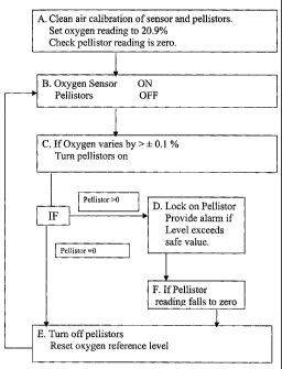
BRIEF DESCRIPTION Op' THE DRAWING
By way of example the a method for the detection of combustible gases or
vapours in air ac;cording to the invention is described below with
5 reference to the accompanying drawing which is block diagxam
representing the instrument and the steps of the said method.
Z1ETAILED DESCRIPTION OF THE PREFERRED EMBODIMENT
10 Referring to the drawing, in Box A the instrument of the present
invention is first calibrated in clean, dry air and the oxygen sensox
reference is set equivalent to 20.9% oxygen. The pellistors are also
calibrated using for example an airlmethane mixture of known methane
concentration. It is also possible to calibrate the activated pellistors and
15 set the oxygen sensor reference point using a single dry ealibratiorc gas
of
known oxygen and methane concentrations.
Box B shows the pellistors de-activated with the oxygen sensor in an
active mode. In this condition, the instruxxtent is ready for use.
20
Box C depicts a situation in which the oxygen sensor output varies by
more than t 0.1 %a oxygen equivalent, namely for a 10% methane LEL
alarm instrument. If the output varies to this extent, the pellistors are
activated for a preset minimum period to allow sufficient time for them to
25 become fully operational.
In Box D, if the pellistors indicate the presence of a combustible gas or
vapour, then they will provide a measure of the combustible gas or
vapour. If the indicated level is or becomes equal to or greater than the
30 preset alarm level, e. g. methane greater than 10% LEL (greater than
CA 02345801 2001-05-03
9
0.5% methane) the instrument will give a suitable alarm. In this case,
a mini,m,uzn level at which the instrument locks on the pellistors will be
preset to allow for any baseline variations of the pellxstors, below which
level of combustible gas concentration it would not be required to
5 maintain the pellistors active.
Box E shows the situation in which the pellistors do not indicate the
presence of any significant concentrations of combustible gas resulting
from the change in oxygen level. In this instance, the instrument de-
10 activates the pellistors and resets the oxygen reference level to the
Current
value and the instrument operation continues from Box B.
Box F represents the step taken in the event that the pellistor reading falls
to zero or an acceptably safe level following on from Box D.
x5
It will be understood that the various operational steps indicated in the
diagram may conveniently be carried out using a suitable microprocessor
control. Alternative and equivalent forms of control may equally well be
employed in combination with the instrument.
20
The use of a cycling on/off control for the sensor or pellistors will be
understood to have a power conservation advantage while not
compromising the efficacy of the instrument.
25 A,s an alternative to the compensator bead a fixed resistor circuit may be
employed and accordingly the invention embraces the use of a detector
bead in combination with such a fixed resistor circuit.
The present invention thus provides an improved method and instrument
30 for detecting combustible gases and vapours having the advantage of
CA 02345801 2001-05-03
10
reduCi~ng power req~uiremez~ts and reducing the poisoning/inhibition
effect, thereby prolonging the potential life of the iristruznent.