Language selection

Search

Patent 2345918 Summary

Third-party information liability

Some of the information on this Web page has been provided by external sources. The Government of Canada is not responsible for the accuracy, reliability or currency of the information supplied by external sources. Users wishing to rely upon this information should consult directly with the source of the information. Content provided by external sources is not subject to official languages, privacy and accessibility requirements.

Claims and Abstract availability

Any discrepancies in the text and image of the Claims and Abstract are due to differing posting times. Text of the Claims and Abstract are posted:

  • At the time the application is open to public inspection;
  • At the time of issue of the patent (grant).
(12) Patent Application: (11) CA 2345918
(54) English Title: TRANSILIAC APPROACH TO ENTERING A PATIENT'S INTERVERTEBRAL SPACE
(54) French Title: APPROCHE TRANSILIAQUE POUR ACCEDER A L'ESPACE INTERVERTEBRAL D'UN SUJET
Status: Dead
Bibliographic Data
(51) International Patent Classification (IPC):
  • A61B 17/56 (2006.01)
(72) Inventors :
  • MARINO, JAMES F. (United States of America)
(73) Owners :
  • NUVASIVE, INC. (United States of America)
(71) Applicants :
  • NUVASIVE, INC. (United States of America)
(74) Agent: STIKEMAN ELLIOTT LLP
(74) Associate agent:
(45) Issued:
(86) PCT Filing Date: 1999-06-04
(87) Open to Public Inspection: 2000-08-24
Availability of licence: N/A
(25) Language of filing: English

Patent Cooperation Treaty (PCT): Yes
(86) PCT Filing Number: PCT/US1999/012610
(87) International Publication Number: WO2000/048521
(85) National Entry: 2000-12-08

(30) Application Priority Data:
Application No. Country/Territory Date
60/120,663 United States of America 1999-02-19
60/129,703 United States of America 1999-04-16
60/088,663 United States of America 1998-06-09

Abstracts

English Abstract


The present invention provides methods for percutaneously accessing the
patient's intervertebral space (18) by creating an access portal (30) through
the patient's ilium (16) and into the patient's intervertebral space (18). The
access portal (30) created is preferably at a posterolateral angle,
(preferably in the range of 40 to 90 degrees to an anterior/posterior axis
through the patient), thereby being at the optimal angle of approach to the
intervertebral space (18) for these lower L5/S1 vertebrae. Methods are also
provided for advancing surgical instruments through the passage, and into the
intervertebral space (18).


French Abstract

L'invention concerne des procédés permettant d'accéder par voie percutanée à l'espace intervertébral (18) d'un sujet en créant un orifice d'accès (30) traversant l'ilion (16) et pénétrant dans l'espace intervertébral (18). Cet orifice d'accès (30) se situe de préférence à un angle postéro-latéral, (de préférence dans une fourchette de 40 à 90 degrés par rapport à un axe antérieur-postérieur traversant le sujet), ce qui constitue l'angle d'approche optimal de l'espace intervertébral (18) pour les vertèbres inférieures L5/S1. L'invention concerne également des procédés permettant d'introduire, par le passage créé, des instruments chirurgicaux dans l'espace intervertébral (18).

Claims

Note: Claims are shown in the official language in which they were submitted.


7


WHAT IS CLAIMED IS:


1. A method of providing a surgical access portal
through a patient's ilium, comprising:
positioning a distal end of a cannulated obturator
against the patient's ilium;
advancing a fastening element through the cannula
of the obturator so that the fastening element reaches the
patient's ilium;
securing the fastening element to the patient's
ilium;
advancing a cannulated bone cutting drill over the
fastening element such that a distal end of the cannulated
bone cutting drill contacts the patient's ilium;
drilling a hole through the patient's ilium with
the bone cutting drill;
removing a circular cut portion of the ilium
attached to the fastening element, thereby providing an
access portal through the patient's ilium.
2. The method of claim 1, further comprising:
introducing the cannulated obturator into the
patient through a percutaneously inserted first cannula.
3. The method of claim 1, further comprising
accessing a patient's intervertebral space by:
inserting a second cannula through the first
cannula; and
advancing a distal end of the second cannula through the
access portal in the ilium and into the patient's
intervertebral space.
4. The method of claim 3, further comprising:
advancing a surgical instrument through the access
portal and into the intervertebral space.


8


5. The method of claim 2, wherein the first
cannula is introduced in a posterolateral approach.
6. The method of claim 5, wherein,
the posterolateral approach is at an angle of
in the range of 40 to 90 degrees to an anterior-posterior
axis through the patient.
7. The method of claim 1, wherein,
the first cannula has a longitudinal axis
extending therethrough and the distal end of the first
cannula is angled with respect to the longitudinal axis,
wherein positioning the distal end of the first cannula
comprises rotating the first cannula about the longitudinal
axis such that the angled end substantially fully contacts
the ilium.
8. The method of claim 1, wherein, securing the
fastening element to the ilium comprises screw-fastening a
distal end of the fastening element into the ilium.
9. The method of claim 1, wherein, the bone
cutting drill and the fastening element are removed
simultaneously from the first cannula with the circular cut
portion of the ilium held within the bone cutting drill.
10. The method of claim 9, wherein, the circular
cut portion of the ilium is removed from the bone cutting
drill by displacing an axially-adjustable plug in the bone
cutting drill.
11. The method of claim 20, wherein, the axially-
adjustable plug is received over the fastening element and
within the bone cutting drill.


9


12. The method of claim 4, wherein advancing a
surgical instrument comprises advancing an intervertebral
insert, bone decorticator, camera, articulating forceps,
intervertebral insert positioning systems, bone-graft
introducer, electrocoagulator, bone wax applicator, shaver
or curette into the intervertebral space.
13. The method of claim 1, further comprising,
depositing bone wax around the surface of the hole
as the hole is drilled through the ilium.
14. A kit for providing a surgical access portal
through a patient's ilium, comprising:
a cannula;
a bone cutting drill dimensioned to be received
within the cannula;
a fastening element dimensioned to be received
within the bone cutting drill; and
instructions for use setting forth the method of
claim 1.
15. A system for providing a surgical access
portal through a patient's ilium, comprising:
a first cannula;
a bone cutting drill dimensioned to be received
within the first cannula; and
a fastening element dimensioned to be received
within the bone cutting drill.
16. The system of claim 15, wherein, the first
cannula has an annular cross-section.
17. The system of claim 15, wherein, the bone
cutting drill is an oscillating drill.


10


18. The system of claim 15, wherein, the
fastening element has a distal end shaped to be screw-fit
into the ilium.
19. The system of claim 15, wherein, the bone
cutting drill has a grooved exterior surface adapted to hold
bone wax or paraffin therein.
20. The system of claim 15, wherein, the first
cannula has an angled distal end.
21. The system of claim 15, wherein, the first
cannula has a round or oval-shaped cross section.
22. The system of claim 15, further comprising, a
second cannula dimensioned to be received within the first
cannula.
23. The system of claim 22, wherein, the second
cannula has a round or oval-shaped cross section.
24. The system of claim 23, further comprising,
an expandable trocar dimensioned to be received within the
first and second cannulae.
25. The system of claim 22, further comprising, a
surgical instrument dimensioned to be received within the
second cannula.
26. The system of claim 25, wherein, the surgical
instrument is an intervertebral insert, bone decorticator,
endoscope, articulating forceps, intervertebral insert
positioning systems, bone-graft introduces,
electrocoagulator, bone wax applicator, shaver or curette.


11


27. The system of claim 15, further comprising,
an intervertebral implant dimensioned to be received within
the first and second cannulae.
Description

Note: Descriptions are shown in the official language in which they were submitted.


CA 02345918 2000-12-08
WO 00/48521 PCT/US99/12610
TRANSII~IAC APPROACH TO ENTERING A PATIENT'S
INTERVERTEBRAL SPACE
CROSS-REFERENCES TO RELATED APPLICATIONS
The present application is a regular application
claiming benefit under 35 USC ~119(e) from U.S. Provisional
Patent Applications Serial No. 60/120,663 filed February 19,
1999; and U.S. Provisional Patent Application No.
60/129,703, filed April 16, 1999: the complete disclosure of
which are hereby incorporated herein by reference in their
entirety for all purposes.
BACKGROUND OF THE INVENTION
A major problem when accessing a patient's
intervertebral space during spinal surgery is the problem of
avoiding sensitive nerves and ligaments during the operative
procedure. When accessing the para-spinal space or a
specific intra-discal space to perform a discal or
intervertebral procedure, the optimal angle of approach to
avoid sensitive nerves and ligaments is a posterolateral
angle. However, this angle of approach is not practical
when accessing the lower vertebrae, specifically the L5/Sl
inter-vertebral space, due to the patient's ilium bone which
blocks such an angle of approach. Consequently, when
performing surgical procedures at L5/S1 it is necessary to
enter the intervertebral space from another angle, thus
increasing the danger of interfering with the cauda equina
and ligaments at such lower vertebrae.
SU1~1ARY OF THE INVENTION
The present invention provides methods for
percutaneously accessing the patient's intervertebral space
by creating an access portal.through the patient's ilium and
into the patient's intervertebral space. The access portal
created by the present invention is preferably at a
posterolateral angle, (preferably in the range of 40 to 90


CA 02345918 2000-12-08
WO 00/48521 2 PCT/US99/12610
degrees to an anterior-posterior axis through the patient),
thereby being at the optimal angle of approach to the
intervertebral space for these lower L5/S1 vertebrae.
Methods are also provided for advancing surgical instruments
through the passage and into the intervertebral space.
A system is also provided for conveying and
depositing bone wax into bone interstices created by the
coring of the ilium, thereby reducing bleeding.
As dual cannulae system of accessing a patient's
intervertebral space is also provided.
BRIEF DESCRIPTION OF THE DRAWINGS
Fig. 1 is a schematic view of a cannulated
obturator inserted percutaneously into t:he patient's back.
Fig. 2 is a schematic view of the cannulated
obturator of Fig. 1 placed in contact with the patient's
ilium, with a screw-fastening element inserted therethrough.
Fig. 3A is a schematic view of a bone cutting
drill adapted with a spiral bonewax depression to deposit
bone wax during cutting, with the fastening element screwed
through the patient's ilium.
Fig. 3B shows the bone cutting drill advanced
through the patient's ilium.
Fig. 4 is a schematic view of a cut-out section of
the patient's ilium being removed by a cannulated fastening
element.
Fig. 5 is a schematic view of a cannulated access
portal through the patient's ilium.
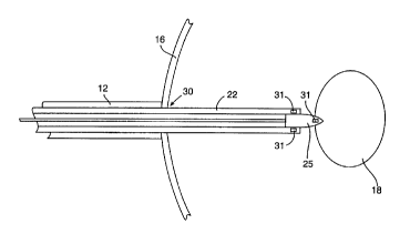
Fig. 6 is a schematic view of a surgical
instrument passing through the patient's ilium and through a
second cannula and into the patient's intervertebral space.
Fig. 7 is an illustration of a pair of
percutaneously inserted cannulae approaching a patient's
ilium in posterolateral angles.
Fig. 8 is an illustration of a pair of
percutaneously inserted cannulae approaching a patient's


CA 02345918 2000-12-08
WO 00/48521 3 PCT/US99/12610
ilium in posterolateral angles with a bone cutter passing
through the patient's ilium.
Fig. 9 is a view of a racetrack-shaped hole
passing through the ilium.
DESCRIPTION OF THE SPECIFIC E1~ODIMENTS
Figs. 1-5 are to be viewed in sequence and show
different aspects of the present method of providing a
surgical access portal through a patient's ilium. Fig. 6
shows a method of inserting a surgical device into the
intervertebral space through a second cannula which is
received through the first cannula and through the access
portal cut in the ilium.
Fig. 1 shows a cannulated obturator 10 received in
a cannula 12 which is percutaneously introduced through the
back 14 of a patient having an ilium 16 and an
intervertebral space 18. Obturator 10 has a narrow tapered
end 11 enabling it to pass through the patient's tissues
such that end 11 can be advanced to a position adjacent
ilium 16 as is seen in Fig. 2. After obturator 10 reaches
ilium 16, cannula 12 can be slipped down thereover such that
a distal end 13 of cannula 12 can be placed in contact with
ilium 16. Preferably, as is shown in Figs. 1 and 2, distal
end 13 of cannula 12 can have a angled end such that it can
be rotated about its longitudinally extending central axis
to abut against ilium 16 although ilium 16 is angled to
cannula 12.
A fastening element is then attached to the ilium.
In a preferred aspect, this fastening element comprises a
screw-type fastening element 20 which is preferably held
within bore 9 of obturator 10. Fastening element 20 can
then be rotated to be screwed into ilium 16, as shown.
As seen in Fig. 3A, obturator 10 is then removed
and a bone cutting device 15, which is preferably hollow as
shown, is inserted into cannula 12 over fastening screw 20
such that bone cutting device 15 abuts against ilium 16.
Screw-type fastening element 20 is received within a hollow


CA 02345918 2000-12-08
WO 00/48521 4 PCT/US99/12610
bore 21 of bone cutter 15 as shown. Back and forth
oscillation or continuous rotation of bone cutter 15 will
eventually bore through ilium 16 to the position shown in
Fig. 3B.
S Bone cutter 15 is adapted to provide for the
conveyance and deposition of bone wax into bone interstices
created by the coring of the ilium, thereby reducing
intraoperative and postoperative bleeding. Specifically,
spiral grooves 23 on the exterior surface of bone cutter 15
are adapted to hold bone wax or paraffin therein such that
the bone wax or paraffin will be heated and melt with the
cutting friction, thereby being deposited into the cored
bone region. Accordingly, bone healing is promoted.
In a preferred aspect, bone cutter 15 comprises an
oscillating "cast" drill (ie: a drill which cuts through
rigid objects but not soft objects), which is adapted to cut
through the hard bony tissue of the ilium without damaging
softer surrounding tissues.
As shown in Fig. 4, oscillation or rotation of
bone cutter 15 will eventually cut out a circular section 19
of ilium 16 which can be removed as follows. Since
fastening element 20 is rotated to be screwed into section
19 of ilium 16, removal of fastening element 20 and bone
cutter 15 from within cannula 20 will thus also cause
circular cut-out section 19, (which is attached to fastening
element 20), to be removed as well. When bone cutter 15 and
fastening element 20 are simultaneously removed, section 19
will preferably remain within the cannula of bone cutter 15.
Rotational or axial movement of fastening element 20
relative to bone cutter 15 will subsequently remove section
19 from the cannula of bone cutter 15. As a result, a
cannulated access portal 30 will be provided passing
percutaneously through the patient's ilium as is shown in
Fig. 5.
Subsequently, as is shown in Fig. 6, a surgical
tool 25 which may comprise an intervertebral insert, bone
decorticator, camera, articulating forceps, intervertebral
insert positioning systems, bone-graft introducer,


CA 02345918 2000-12-08
WO 00/48521 5 PCT/US99/12610
electrocoagulator, bone wax applicator, shaver or curette,
can then be inserted through cannula 20 and through ilium 16
such that surgical tool 25 can reach intervertebral space
18. Specifically, in a preferred aspect, a second cannula 22
is dimensioned to be slidably received within first cannula
12 such that cannula 22 can be advanced to intervertebral
space 18. Surgical tool 25 can then be inserted therethrough
such that surgical tool 25 can be positioned at
intervertebral space 18, as shown. In a preferred aspect,
the second cannula may have an oval cross section.
In another preferred aspect, nerve. surveillance
electrodes 31 are positioned at the distal end of cannula 22
or on surgical device 25, (which may comprise a blunt
obturator). Electrodes 31 can be adapted to sense the
presence of a para-spinal nerve as cannula 22 is advanced
through access portal 30. In alternative aspects,
expandable trocars may be inserted through cannula 22 to
access the patient's intervertebral space.
Cut-out section 19 can itself be used as bone
graft material for packing around or within intervertebral
inserts which are positioned in the intervertebral space
using the present system.
As is shown in Fig. 9, a racetrack-shaped hole 40
can be drilled through the ilium 16 by sequentially drilling
overlapping first and second circular holes 42 and 44 using
the present method. As can be appreciated holes of various
shapes, (including elongated racetrack shapes), can be
drilled through the patient's ilium. An advantage of
racetrack-shaped hole 40 is that it permits cannulae having
oval or racetrack-shaped cross sections to be passed through
ilium 16, and into the patient's intervertebral region.
As the present invention is adapted to provide a
passage through the patient's ilium as is set forth herein,
an optimal posterolaterally angled access portal through to
the patient's L5/S1 intervertebral spaces can be provided.
Fig. 7 shows a pair of percutaneously inserted
cannulae 12 approaching the patient's ilium 16 in
posterolateral angles, which are preferably in the range of


CA 02345918 2000-12-08
WO 00/48521 6 PCT/US99/12610
40° to 90° to an anterior axis through the patient. Fig. 8
shows the pair of percutaneously inserted cannulae 12
positioned against the patient's ilium 16 in posterolateral
angles with the distal end of bone cutter 15 passing through
patient's ilium 16.
The present invention also provides kits for
providing a surgical access portal through a patient's
ilium, comprising: a cannula; a bone cutting drill
dimensioned to be received within the cannula; a fastening
element dimensioned to be received within the bone cutting
drill; and instructions for use setting forth any of the
methods herein described.
The present invention also provides kits for
providing access to a patient's intervertebral space through
a patient's ilium, comprising: a first cannula; a bone
cutting drill dimensioned to be received within the first
cannula; a fastening element dimensioned to be received
within the bone cutting drill; and instructions for use
setting forth any of the methods herein described.

Representative Drawing
A single figure which represents the drawing illustrating the invention.
Administrative Status

For a clearer understanding of the status of the application/patent presented on this page, the site Disclaimer , as well as the definitions for Patent , Administrative Status , Maintenance Fee  and Payment History  should be consulted.

Administrative Status

Title Date
Forecasted Issue Date Unavailable
(86) PCT Filing Date 1999-06-04
(87) PCT Publication Date 2000-08-24
(85) National Entry 2000-12-08
Dead Application 2003-06-04

Abandonment History

Abandonment Date Reason Reinstatement Date
2002-06-04 FAILURE TO PAY APPLICATION MAINTENANCE FEE

Payment History

Fee Type Anniversary Year Due Date Amount Paid Paid Date
Application Fee $300.00 2000-12-08
Registration of a document - section 124 $100.00 2001-01-08
Maintenance Fee - Application - New Act 2 2001-06-04 $100.00 2001-05-31
Owners on Record

Note: Records showing the ownership history in alphabetical order.

Current Owners on Record
NUVASIVE, INC.
Past Owners on Record
MARINO, JAMES F.
Past Owners that do not appear in the "Owners on Record" listing will appear in other documentation within the application.
Documents

To view selected files, please enter reCAPTCHA code :


To view images, click a link in the Document Description column. To download the documents, select one or more checkboxes in the first column and then click the "Download Selected in PDF format (Zip Archive)" or the "Download Selected as Single PDF" button.

List of published and non-published patent-specific documents on the CPD .

If you have any difficulty accessing content, you can call the Client Service Centre at 1-866-997-1936 or send them an e-mail at CIPO Client Service Centre.


Document
Description 
Date
(yyyy-mm-dd) 
Number of pages   Size of Image (KB) 
Representative Drawing 2001-06-20 1 4
Cover Page 2001-06-20 1 31
Abstract 2000-12-08 1 50
Description 2000-12-08 6 280
Claims 2000-12-08 5 145
Drawings 2000-12-08 10 122
Assignment 2000-12-08 3 102
PCT 2000-12-08 19 778
Prosecution-Amendment 2000-12-08 1 26
Assignment 2001-01-08 5 225
Prosecution-Amendment 2001-07-24 12 135
Fees 2001-05-31 1 56