Note: Descriptions are shown in the official language in which they were submitted.
CA 02346183 2001-04-03
WO 00/20902 PCT/US99l17062
1
DESCRIPTION
MIRROR COATING, MIRROR UTILIZING SAME, AND A MIRROR
ASSEMBLY
Technical Field
The present invention relates to a mirror coating, mirror employing same
and a mirror assembly, and more particularly to an invention which finds
utility
when coupled with the controls of an overland vehicle of the like, and which
may, on the one hand, and in one form of the invention, operates as a
combined warning lamp and rear view mirror assembly.
l0 Background Art
The beneficial effects of employing auxiliary signaling assemblies have been
disclosed in various United States patents, including 11.5. Patents Nos.
5,014,167;
5,207,492; 5,355,284; 5,361,190; 5,481,409; and 5,528,422, all of which are
incorporated by reference herein. The mirror assemblies disclosed in the above-
captioned patents employ a dichroic mirror which is operable to reflect a
broad
band of electromagnetic radiation, within the visible light portion of the
spectrum,
while simultaneously permitting electromagnetic radiation having wavelengths
which
reside within a predetermined spectral band to pass therethrough. In this
fashion, the dichroic mirror remains an excellent visual image reflector, that
is,
2o achieving luminous reflectance which is acceptable for automotive and other
industrial applications, for example, while simultaneously achieving an
average
transmittance in the predetermined spectral band of at least 58% . Further,
when
the predetermined band pass region is relatively narrow, that is, such as 30
manometers or more, average in-band transmittance of 80% or more can be
2s achieved with peak transmittance in excess of 90% being common.
In U.S. Patent hlo. 5,528,422, a plurality of mirror coatings were disclosed
and which are operable to conceal an underlying sensor or light-emitting
assembly
while simultaneously providing a neutral chromatic appearance. These same
mirror coatings simultaneously absorb wavelengths of electromagnetic radiation
30 which may otherwise be transmitted into the mirror assembly and which
would,
over time, degrade or otherwise be harmful to the subassembly which is
concealed by the mirror assembly.
In still another reference, U.S. Patent No. 5,788,357, a mirror assembly
is disclosed and which includes a semitransparent nondichroic mirror which
passes
35 8% or less of substantially all visible light, and which reflects about 35%
to
about 85% of a broad band of visible light; and a light assembly which emits
CA 02346183 2001-04-03
WO 00/20902 PCTNS99/17062
2
visible light which is passed by the semitransparent mirror, the luminous
intensity
to the mirror assembly being about 2 to about 20 candelas. The teachings of
this reference are incorporated by reference herein.
While the devices disclosed in these patents have realized some degree
s of commercial success, certain inherent physical characteristics of the
earlier
disclosed mirror assemblies have somewhat impeded manufacturing efforts to
cost
effectively mass produce these same assemblies. For example, while the mirror
coatings disclosed in Patent No. 5,528,422 operate as described, the
manufacturing
difficulties and costs associated with producing these rather complex coatings
with
commercially available coating fabrication equipment has impeded the
introduction
of low cost products for the mass market. Similar difficulties have hampered
the
introduction of products fabricated in accordance with the teaching of U.S.
Patent
No. 5,788,357. Yet further, as the size of mirror housings have decreased in
volume as a result of the recent automotive platform design changes, the
amount
~5 of available space within these same housings has become quite limited.
Therefore, the size and weight of the enclosed light-emitting assembly or
sensor
has become a factor in the commercial introduction of a suitable product.
Other devices have attempted to diverge from the teachings provided in
the patents noted above. These devices, however, when built in accordance with
zo their teachings, have been unable to provide the same performance
characteristics.
An example of such prior art is the patent to Crandall, U.S. Patent 5,436,741.
Other prior art references describe devices which attempt to provide the same
functional benefits, as described in the earlier patents. These references
describe
all manner of mirror housing modifications, where for example, lamps are
located
25 in various orientations to project light into predetermined areas both
internally,
and\or besides the overland vehicle, and to further provide auxiliary
signaling or
warning capability. Examples of such patents include 4,583,155; 4,646,210;
4,916,430; 5,059,015; 5,303,130; 5,371,659; 5,402,103; and 5,497,306 to name
but
a few.
3o Other prior art references have attempted to provide a combined mirror
and signaling assembly. These assemblies have employed a nondichroic,
semitransparent mirror. Perhaps the earliest and most germane patent which
discloses this type of assembly is the patent to Maruyama et al U.S. Patent
No.
3,266,016. This reference was however devoid of any suggestion of how one
35 would manufacture a device which would have both an acceptable
reflectivity, and
an acceptable luminous output, while simultaneously avoiding the detriments
CA 02346183 2001-04-03
WO 00/20902 PCTNS99/17062
3
associated with the build up, and accumulation of heat within the mirror
housing,
and further being functional within the limited spacial area provided for by
the
same . mirror housing. Similar problems are evident in the patent to
Gotzinger,
2,263,382, which discloses a mirror signal device. This device includes a
mirror
mounted in a bell or housing which contains an electric lamp. The mirror has
a transparent backing or silvering which becomes non-reflecting when
illuminated
from behind. The invention permits light to pass only through a lighted area
of the mirror in the form of a signal or symbol. This is done by means of a
stencil in the back of the mirror, and may be further enhanced by a colored
o transparency.
To a limited extent, the reference to Muth et al., U.S. Patent No.
5,788,357, addresses some of the apparent or perceived problems of utilizing a
semitransparent nondichroic mirror in a mirror assembly as described above.
However, and as noted above, the manufacturing problems associated with
~5 producing a cost-effective semitransparent coating within the operational
parameters as discussed in that same patent has impaired its successful
commercial introduction.
In the present invention, the inventor has departed from the teachings of
the prior art, noted above, by providing, in one aspect, a mirror coating
which
2o has a primary region which reflects visibly discernible electromagnetic
radiation,
and a secondary region which passes a portion of the visibly discernible
electromagnetic radiation while simultaneously reflecting a given percentage
of the
visibly discernible electromagnetic radiation, and wherein the average
reflectance
of the mirror coating is greater than about 50%. In the preferred form of the
z5 invention, the primary region reflects less than about 80% of the given
band of
visibly discernable electromagnetic radiation and the secondary region
reflects at
least about 35 % of the same given band of electromagnetic radiation, the
mirror
employing the mirror coating having an average reflectance of at least about
SO%
The mirror as described, may be utilized in a mirror assembly which includes
3o about 1 to about 30 light emitting diodes and which are positioned adjacent
to
the secondary region. These light emitting diodes, when energized, have a
cumulative luminous output of about 1 to about 1000 candelas and the luminous
output of the secondary region is about 0.5 to about 120 candelas.
CA 02346183 2001-04-03
WO 00/20902 PCTNS99/17062
4
Objects and Summary of the Invention
Therefore, one aspect of the present invention is to provide an improved
mirror coating, mirror utilizing same, and mirror assembly.
Another aspect of the present invention is to provide a mirror assembly
which may be manufactured and installed as original equipment on an overland
vehicle or the like or which may be further manufactured in the manner of a
retrofit and substantially equivalent to an original equipment installation.
Another aspect of the present invention is to provide a mirror which may
be readily installed or integrated with other mirror technologies, such as
motorized actuators, heater films, and films of various types, including
diffractive,
holographic, reflective, and electrochromic devices of various designs.
Another aspect of the present invention is to provide a mirror which has
a primary region which is substantially opaque, and wherein the mirror further
has a secondary region which has a given surface area which is about 1 % to
5 about 80% of the surface area of the primary region.
Another aspect of the present invention is to provide a mirror which has
a secondary region which comprises a mirror coating having a plurality of
individual apertures having given cross sectional areas formed therein, and
wherein the cumulative cross sectional areas of the individual apertures
comprise
20 less than about 60% of the surface area of the secondary region.
Another aspect of the present invention is to provide a mirror which has
a secondary region which passes about 1 % to about 80% of the visibly
discernible electromagnetic radiation directed at same.
Another aspect of the present invention is to provide in one form of the
25 invention, a mirror assembly which includes an electromagnetic radiation
emitter
positioned adjacent to the secondary region of the mirror, and which emits
visible
light which is passed by the secondary region, the luminous output of the
secondary region of the mirror being about 0.5 to about 120 candelas.
Another aspect of the present invention is to provide in one form of the
3o invention, a mirror assembly which includes an electromagnetic radiation
emitter
positioned adjacent to the secondary region of the mirror, and which has a
luminous output of about 1 candela to about 1000 candelas.
Yet still another aspect of the present invention is to provide a mirror
assembly having a secondary region which has a light emitting surface area of
35 about 10 to about 4000 millimeters.
CA 02346183 2001-04-03
WO 00/20902 PCT/US99/17062
Yet further, another aspect of the present invention is to provide a mirror
assembly which is operable to obtain the individual benefits to be derived
from
related prior art assemblies and devices while avoiding the detriments
individually
associated therewith.
5 Further aspects and advantages of the present invention are to provide
improved elements and arrangements thereof in a mirror, mirror coating
utilized
with same, and mirror assembly for the purposes described, and which is
dependable, economical, durable, and fully effective in accomplishing these
intended purposes.
These and other aspects and advantages are achieved in a mirror coating
which comprises a primary region which reflects visibly discernible
electromagnetic
radiation, and a secondary region which passes electromagnetic radiation while
simultaneously reflecting a given percentage of visibly discernible
electromagnetic
radiation.
Brief Description of the Drawings
Preferred embodiments of the invention are described below with reference
to the following accompanying drawings.
Figure 1 is a perspective, front elevation view of a mirror assembly of the
present invention in a deenergized state.
2o Figure 2 is a perspective, front elevation view of a mirror assembly of the
present invention in an energized state.
Figure 3 is a greatly enlarged, partial, plan view taken from a position
along line 3-3 of Figure 1.
Figure 4 is a greatly enlarged, partial, plan view taken from a position
along line 3-3 of Figure 1, and showing an alternative arrangement to that
shown in Figure 3.
Figure 5 is a greatly enlarged, partial, plan view taken from a position
along line 3-3 of Figure 1, and showing still further an alternative
arrangement
to that shown in Figures 3 and 4.
3o Figure 6 is a partial, vertical sectional view of the mirror and which is
taken along lines 6-6 of Figure 2.
Figure 7 is a greatly enlarged, vertical sectional view of the mirror taken
from a position along line 6-6 of Figure 2, and which illustrates an
alternative
form from that shown in Figure 6.
Figure 8 is an exploded, perspective view of a mirror assembly of the
present invention.
CA 02346183 2001-04-03
WO 00/20902 PCT/US99/17062
6
Figure 9 is a greatly enlarged, fragmentary, vertical sectional view taken
from a position along line 6-6 of Figure 2, and showing a light emitting
assembly utilized with same. The proportional relationship of this drawing is
greatly exaggerated in order to facilitate an understanding of the invention.
Best Modes for CarTVinL Out the Invention and Disclosure of Invention
A mirror assembly which utilizes a mirror, and mirror coating of the
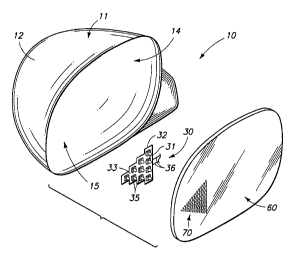
present invention, is best indicated by the numeral 10 in Figures 1, 2, and 8,
respectively. As shown therein, the mirror assembly 10 includes a mirror
housing
11 which has a substantially continuous sidewall 12. The continuous sidewall
has
a peripheral edge 13 which defines an aperture 14 (Fig. 8) of given
dimensions.
Further, this substantially continuous sidewall defines a cavity 15. It should
be
understood that the mirror housing is mounted on an overland vehicle of
conventional design (not shown). The housing will be placed within the line of
sight of an operator in a position normally occupied by an exterior rear view
~5 mirror. However, it should be understood that the present device is not
limited
to use on overland vehicles, but may be used in all manner of industrial
applications, including signs, and various visual displays.
As seen in Fig. 8, enclosed within the cavity 15 is a light emitting
assembly which is designated by the numeral 30. The light emitting assembly
2o includes a supporting, substantially nonconductive substrate 31 which is
defined
by a peripheral edge 32. The supporting substrate has a forward facing surface
33 and an opposite rearward facing surface 34. Conductive traces, not shown,
may be formed on either the forward or rearward facing surfaces, more
commonly the forward facing surface 33. The conductive traces are electrically
25 coupled with a plurality of light emitting diodes 35 which are affixed on
the
forward facing surface 33. The conductive traces which are formed on either
the forward or rearward facing surfaces 33 or 34 are electrically coupled to
an
automotive or other electrical system by means of the electrical leads 36. As
should be understood, the supporting substrate 31 provides a light emitting
3o surface area of about 10 to about 4000 square millimeters. Of course, the
surface area of the nonconductive substrate is typically larger than this.
Further,
about 1 to about 30 light emitting diodes are mounted on the supporting
substrate and may be placed in a given geometrical pattern such as a triangle
as shown, or other patterns based upon the ultimate end use. The supporting
35 substrate 31, and the light emitting . diodes 35 have a combined weight of
normally less than about 100 grams when used in automotive applications.
CA 02346183 2001-04-03
WO 00/20902 PCT/US99/17062
7
Further, it should be understood that the light emitting diodes when
energized,
emit visibly discernible electromagnetic radiation or other substantially
invisible
radiation. The luminous output of the about 1 to about 30 light emitting
diodes
35 is about 0.5 to about 1000 candelas. As seen from a study of Figure 8, the
substrate and related light emitting diodes are formed generally or roughly
into
the shape of a triangle or pyramid-like shape, but any alpha-numeric
designation
or geometric or fanciful shape may be formed and which could be viewed from
a position exterior to the mirror housing 11. Further, all manner of different
optical assemblies may be utilized in combination with the light emitting
diodes
35 to coliimate, reflect, or otherwise direct the light emitted from same in a
given direction, pattern, or intensity of distribution relative to the
supporting
substrate. Such is disclosed in the earlier prior art patents which are
incorporated by reference herein.
A mirror 50 is disposed in substantially occluding relation relative to the
~5 aperture 14 which is defined by the mirror housing i 1. The mirror 50
comprises a supporting substantially transparent substrate 51 which has a
forward
facing surface 52, and an opposite rearward facing surface 53, (Figure 9). A
mirror coating 54 (Figures 6 and 7) is applied on the rearwardly facing
surface
53. As should be understood, the mirror coating may be applied in an
2o alternative form to the forward facing surface. The discussion which
follows,
therefore, is applicable to mirrors where the mirror coating is applied to
either
the forward or rearward facing surfaces. The mirror coating 54 may comprise
any number of different, highly reflective or mirror-like coatings or
substances
such as chromium or the like, and which may be applied in a manner which
25 provides a commercially acceptable reflective surface. As best seen by
reference
to Figures 1 and 2, the mirror 50 has a primary region 60, and an adjacent
secondary region 70. While only two regions are shown it is possible, of
course,
to have a plurality of secondary regions as operational conditions may
dictate.
As a general matter, the primary region b0 reflects visibly discernible
3o electromagnetic radiation and is nominally opaque, and the secondary region
70
passes a portion of the visibly discernible electromagnetic radiation directed
at
same while simultaneously reflecting a given percentage of the visibly
discernible
electromagnetic radiation. The average reflectance of the overall mirror
coating
54, including both the primary and secondary regions is greater than about 50%
35 when employed for automotive applications. In other industrial
applications, the
average reflectance may be lower or higher, depending upon the desired end-
use.
CA 02346183 2001-04-03
WO 00/20902 PCT/US99/17062
8
As seen in the drawings, the primary region 60 is substantially continuous,
and
reflects, for automotive applications, less than about 80% of the visibly
discernible electromagnetic radiation striking this portion of the overall
mirror 50
surface area. The primary and secondary regions each have a given surface
area. Still further, the primary region 60 passes on average less than about 1
of the visibly discernible electromagnetic radiation striking its surface, and
the
secondary region passes about 1 % to about 65 % of the same visibly
discernible
electromagnetic radiation. In the preferred form of the invention, the
secondary
region reflects at least about 35 % of the visibly discernible electromagnetic
radiation striking its surface. These ranges have been found suitable for
automotive applications, however, other broadened or narrowed ranges may be
useful for other industrial applications.
As best seen by reference to Figures 3, 4, and 5, the mirror coating 54
in the secondary region 70, of the mirror 50 includes a plurality of discrete
l5 apertures 71 which may be formed in a number of given patterns and in
various
densities. As seen in Figures 7 and 9, which are greatly exaggerated
representations of the invention, the plurality of discrete apertures 71
extend
substantially through the coating to the surface 53 of the transparent
substrate
S1. In an alternative form of the invention, as shown in Figure 6, reduced
20 thickness areas 74 may be formed in the mirror coating, it being understood
that
the reduced thickness areas 74 allow visible electromagnetic radiation to pass
therethrough to a greater extent then the adjacent thicker areas. Such reduced
thickness areas might be achieved by means of laser oblation, chemical
mechanical polishing, and other similar techniques.
25 The plurality of discrete apertures 71 as formed in the mirror surface,
may comprise round apertures 72 (Figure 3); elongated apertures 73 (Figure 5);
or mixtures thereof (Figure 4). Such mixtures of aperture shapes may also
include continuous lines or other geometric patterns which may or may not be
symmetrical in either the shape of the apertures or the overall distribution
or
30 location of the apertures. The discrete apertures 71 have a given cross-
sectional
area. In particular, the cumulative cross-sectional areas of the given
apertures
is less than about 60% of the surface area of the secondary region 70. When
the discrete apertures which are selected are substantially round 72, the
given
apertures have a diametral dimension of about .001 millimeters to about .015
35 millimeters. Still further, the round apertures 72 are spaced apart about
.005
millimeters to about .OS millimeters when measured center-to-center. As seen
CA 02346183 2001-04-03
WO 00/20902 PCT/US99/17062
9
in Figure 9, the mirror S0, including the mirror coating S4, and the light
emitting assembly 30 comprise an optical stack 7S, which has a thickness of
less
than about 25 millimeters. When assembled, the resulting optical stack, when
energized, creates less than about 18 milliwatts of heat energy per square
millimeter of surface area of the substrate 31, and further, the light
emitting
diodes 35 emit visibly discernible electromagnetic radiation which is passed
by the
secondary region such that the secondary region has a luminous output of about
0.S to about 120 candelas. Such is best illustrated in Figure 2. As best seen
by a comparison between Figures 1 and 2, the primary region 60 of the mirror
SO is an excellent reflector of visible electromagnetic radiation. Further,
the
secondary region 70 while it has been rendered operable to transmit
electromagnetic radiation, remains an acceptable reflector such that an image
can
be perceived in same while electromagnetic radiation passes therethrough.
Still
further, the distribution and size of the apertures in the secondary region
permits
the easy adjustment of the reflective and transmission valves for this same
region
to produce a predetermined luminous output for specific industrial
applications.
Operation
The operation of the described embodiments of the present invention are
believed to be readily apparent and are briefly summarized at this point.
2o A first aspect of the present invention relates to a mirror coating
comprising a primary region 60 which reflects visibly discernible
electromagnetic
radiation, and a secondary region 70 which passes a portion of the visibly
discernible electromagnetic radiation while simultaneously reflecting a given
percentage of the visibly discernible electromagnetic radiation. The average
reflectance of the entire mirror coating is greater than about SO% .
A further aspect of the present invention relates to a mirror SO
comprising a supporting substrate S1 having opposite surfaces S2 and S3
respectively; and a mirror coating S4 disposed on one of the surfaces of the
substrate, and wherein the mirror coating S4 defines a primary region 60 which
3v reflects less than about 80% of a given band of visibly discernible
electromagnetic radiation, and a secondary region 70 through which
electromagnetic radiation may pass, and wherein the secondary region 70
reflects
at least about 3S% of the same given band of electromagnetic radiation.
Yet a further aspect of the present invention relates to a mirror assembly
10 comprising a substantially transparent substrate S1 having opposite
surfaces S2
and S3 respectively, and a given surface area; a mirror coating S4 disposed on
CA 02346183 2001-04-03
WO 00/2fl902 PC'T/US99/17062
one of the surfaces of the substantially transparent substrate 51, and wherein
the
mirror coating 54 defines a primary region 60 which reflects less than about
80
of a given band of visibly discernible electromagnetic radiation, and a
secondary
region 70 through which electromagnetic radiation may pass. Tl:e secondary
5 region 70 comprises about 1 % to about 80% of the surface area of the
substantially transparent substrate 51. Further, the secondary region 70
reflects
at least about 35 % of the same given band of visibly discernible
electromagnetic
radiation. The secondary region 70 is defined by a plurality of discrete
apertures
71 which are formed in the mirror coating 54. Further, the mirror assembly 10
comprises about 1 to about 30 light emitting diodes 35 which are positioned
adjacent to the secondary region 70, and which, when energized, have a
cumulative luminous output of about 1 to about 1000 candelas. Further, the
luminous output of the secondary region is about 0.5 to about 120 candelas.
As noted above, the plurality of discrete apertures 71 may be formed by
~5 all manner of techniques including laser oblation, chemical mechanical
polishing,
and other techniques. The average reflectance of the overall mirror 50,
however,
remains, on average, at least about 50%; and the average luminous reflectance
of the secondary region 71 is at least about 35%, and its average
transmittance
is at least about 1 % to about 65 % .
2D