Language selection

Search

Patent 2346196 Summary

Third-party information liability

Some of the information on this Web page has been provided by external sources. The Government of Canada is not responsible for the accuracy, reliability or currency of the information supplied by external sources. Users wishing to rely upon this information should consult directly with the source of the information. Content provided by external sources is not subject to official languages, privacy and accessibility requirements.

Claims and Abstract availability

Any discrepancies in the text and image of the Claims and Abstract are due to differing posting times. Text of the Claims and Abstract are posted:

  • At the time the application is open to public inspection;
  • At the time of issue of the patent (grant).
(12) Patent: (11) CA 2346196
(54) English Title: MECHANISM FOR PAPER TOWEL DISPENSERS
(54) French Title: MECANISME POUR DISTRIBUTEUR D'ESSUIE-TOUT
Status: Deemed expired
Bibliographic Data
(51) International Patent Classification (IPC):
  • A47K 10/36 (2006.01)
(72) Inventors :
  • NIADA, GIANADREA (Italy)
(73) Owners :
  • QTS S.R.L. (Italy)
(71) Applicants :
  • QTS S.R.L. (Italy)
(74) Agent: GOWLING WLG (CANADA) LLP
(74) Associate agent:
(45) Issued: 2008-09-23
(22) Filed Date: 2001-05-02
(41) Open to Public Inspection: 2001-11-08
Examination requested: 2006-03-06
Availability of licence: N/A
(25) Language of filing: English

Patent Cooperation Treaty (PCT): No

(30) Application Priority Data:
Application No. Country/Territory Date
00201639.2 European Patent Office (EPO) 2000-05-08

Abstracts

English Abstract

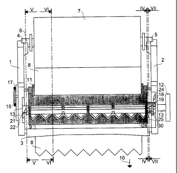
Mechanism for cutting and distributing portions of sheet, particularly paper towels, comprising at least one cylinder (9) which can rotate around its axis in a supporting structure (1, 2, 3) and drag an end portion (8) of at least one sheet, inside said cylinder (9) being arranged one or more movable blades (28) which can protrude outside the cylinder (9) for cutting said end portion (8) of the sheet and are fixed to a shaft (26) suitable for rotating around an axis parallel to the longitudinal axis of the cylinder (9), wherein said shaft (26) is provided with at least a first member (30) which protrudes from one side of the cylinder (9) and can be rotated for an arc of a circumference by at least a second member (25) which shifts in a direction parallel to the longitudinal axis of the shaft (26) of the movable blades (28) and rotates around this axis, the rotational-translational motion of this second member (25) being synchronized with the rotatory motion of the cylinder (9). The present invention also relates to a paper towel dispenser comprising said mechanism.


French Abstract

Un mécanisme pour couper et pour distribuer des sections de feuilles, en particulier de l'essuie- tout, comportant au moins un cylindre (9) qui peut tourner autour de son axe dans une structure de support (1, 2, 3) et qui peut tirer une partie d'extrémité (8) d'au moins une feuille, à l'intérieur dudit cylindre (9) étant agencées une ou plusieurs lames mobiles (28) qui peuvent faire saillie à l'extérieur du cylindre (9) pour couper ladite partie d'extrémité (8) de la feuille et qui sont fixées sur un arbre (26) adapté pour tourner autour d'un axe parallèle à l'axe longitudinal du cylindre (9), caractérisé en ce que ledit arbre (26) est muni d'au moins un premier élément (30) qui fait saillie à partir d'un côté du cylindre (9) et qui peut être tourné sur un arc de circonférence par au moins un second élément (25) qui se déplace dans une direction parallèle à l'axe longitudinal de l'arbre (26) des lames mobiles (28) et qui tourne autour de cet axe, le mouvement rotation-translation de ce second élément (25) étant synchronisé avec le mouvement rotatif du cylindre (9). La présente invention se rapporte également à un distributeur d'essuie-tout comprenant ledit mécanisme.

Claims

Note: Claims are shown in the official language in which they were submitted.


-5-

CLAIMS


1. Mechanism for cutting and dispensing portions of sheets, comprising
at least one cylinder (9) which can rotate around its axis in a supporting
structure (1,
2, 3) and drag an end portion (8) of at least one sheet, inside said cylinder
(9) being
arranged one or more movable blades (28) which can protrude outside the
cylinder
(9) for cutting said end portion (8) of the sheet and are fixed to a shaft
(26) suitable
for rotating around an axis parallel to the longitudinal axis of the cylinder
(9),
characterized in that said shaft (26) is provided with at least a first member
(30)
which protrudes from one side of the cylinder (9) and can be rotated for an
arc of a
circumference by at least a second member (25) which shifts in a direction
parallel to
the longitudinal axis of the shaft (26) of the movable blades
(28) and rotates around this axis, the rotational-translational motion of this
second
member (25) being synchronized with the rotatory motion of the cylinder (9).

2. Mechanism according to claim 1, characterized in that said second
member (25) is a pin fixed to one side of a first toothed wheel (19) suitable
for
rotating around the longitudinal axis of the shaft (26) of the movable blades
(28).

3. Mechanism according to claim 2, characterized in that said first
toothed wheel (19) is engaged with a second toothed wheel (18) which is fixed
to
said supporting structure (1, 2, 3) and is coaxial with the longitudinal axis
of said
cylinder (9).


4. Mechanism according to claim 3, characterized in that said toothed
wheels (18, 19) have the same number of teeth.


5. Mechanism according to one of claims 2 to 4, characterized in that
said first toothed wheel (19) is shifted with an alternated motion
synchronized with
the rotatory motion of the cylinder (9) along the longitudinal axis of the
shaft
(26) by means of one or more guides (22, 24) fixed to said supporting
structure (1,
2, 3).


6. Mechanism according to claim 5, characterized in that the
supporting structure (1, 2, 3) comprises a pair of side walls (1, 2), the
internal
surfaces of which are provided with relieves (22, 24) acting as guides.


-6-

7. Mechanism according to claim 6, characterized in that said relieves
(22, 24) acting as guides have a gradually varying thickness and extend
themselves
for about one quarter of a circumference around the longitudinal axis of the
cylinder (9).

8. Mechanism according to claim 6 or 7, characterized in that said side
walls (1, 2) of the supporting structure are crossed by a pair of hubs (13)
coaxially
fixed to the lateral surfaces of the cylinder (9).

9. Mechanism according to claim 8, characterized in that the external
end of a hub (13) is provided with a round handle (12).

10. Mechanism according to claim 8 or 9, characterized in that the
rotation of the cylinder (9) is opposed for half of a turn and then pushed for
the
next half of a turn by tension elastical means (15) fixed to a side wall (1)
of the
supporting stricture and to a rotating member (16) which is fixed to the
external
end of a hub (13) of cylinder (9) and is arranged externally of the side wall
itself.

11. Mechanism according to claim 11, characterized in that said
rotating member (16) comprises a disk partially toothed with oblique teeth,
which
is suitable for being blocked by a spike (17) hinged to said side wall
(1) of the support structure.

12. Mechanism according to any one of claims 1 to 11, characterized in
that said first toothed wheel (19) can slide along the internal surface of a
side wall
(2) of the supporting structure and is arranged at one end of a rod (20) which

longitudinally crosses cylinder (9) and can slide therein, the other end of
the rod
(20) being provided with a skid (21) which can slide along the internal
surface of
the other side wall (1) of the supporting structure.

13. Mechanism according to claim 12, characterized in that the shaft
(26) of the blades (28) is coaxially arranged around said rod (20) and can
rotate
parallely to the longitudinal axis of the cylinder (9) in seats (27) made in
the
cylinder itself.

14. Mechanism according to any one of claims 1 to 13, characterized in
that said movable blades (28) are curved and provided with triangular points.


-7-

15. Mechanism according to any one of claims 1 to 14, characterized in
that the rotation of the shaft (26) of the movable blades (28) when these
protrude
from the cylinder (9) is opposed by tension elastic means (29) arranged inside
the
cylinder itself.

16. Mechanism according to claim 1, characterized in that said first
member (30) protrudes from one side of the cylinder (9) through one opening
(31) which extends itself for about on quarter of a circumference coaxially
with the
longitudinal axis of the shaft (26) of the movable blades (28).

17. Dispenser of towels of paper or other material wound in a roll (7),
characterized in that it comprises a mechanism according to any one of claims
1 to
16.


Description

Note: Descriptions are shown in the official language in which they were submitted.


CA 02346196 2001-05-02
- 1 -

"MECHANISM FOR PAPER TOWEL DISPENSERS"

The present invention relates to a mechanism for paper towel dispensers,
and particularly to a mechanism suitable for cutting and distributing sheets
of
paper or of another material after taking them from a roll. The present
invention
also relates to a paper towel dispenser comprising said mechanism.
EP 871390 discloses a mechanism for paper towel dispensers comprising a
cutting device having at least one movable blade arranged inside a cylinder,
which
drags the sheet of paper taken from a roll. However, said known mechanism
involves a considerable manufacture and maintenance complexity, as well as a
non-efficient fttnctioning of the cutting device, with risk of jamming of the
mechanism itself.
Object of the present invention is therefore to provide a mechanism which is
free from said drawbacks. Said object is achieved by a nlechanism, the main
features of which are specified in the first claim and other features are
specified in

the following claims. By virtue of the particular rotational-translational
drive system which it is

provided with, the cutting device of the mechanism according to the present
invention has a precise and fluent inovement of the blades outwards from the
cylinder.
Further, thaiiks to the pair of mutually engaged toothed wheels and to the
guides of the supporting structure, said movement of the blades is perfectly
synchronized with that one of the cylinder, so as to avoid the mechanism
jamming.
According to a particular aspect of the invention, the translatory movement
of the member transmitting the rotation to the movable blades is caused by a
pair
of relieves made inside the supporting structure of the cylinder, so as to
obtain a
precision of movement without complex and/or expensive guides.
Further advantages and features of the mechanisin according to the present
invention will appear to those skilled in the art from the following detailed.
and
non-limiting description of one einbodiment thereof with reference to the


CA 02346196 2001-05-02

-2-
accompanying drawings, wherein:
- figure 1 shows a left side view of the mechanism according to said
embodiment;
- figure 2 shows a right side view of the mechanism of figure 1;
- figure 3 shows a front view of the mechanism of figure l.;
- figure 4 shows a side cross-sectioned view of the mechanism of figure 3
taken
along plane IV-IV;
- figure 5 shows a side cross-sectioned view of the mechanism of figure 3
taken
along plane V-V;
- figure 6 shows a side cross-sectioned view of the mechanism of figure 3
taken
along plane VI-VI; and
- figure 7 shows a side cross-sectioned view of the meclianism of figure 3
taken
along plane VII-VII.
With reference to figures 1 to 3, it is seen that the mechanism according to
said embodiment of the invention comprises in a known way a supporting
structure formed of a pair of side walls 1, 2 mutually connected by means of
at
least one profiled transverse bar 3 acting as a lower guide. This supporting
sti-ucture can be mounted inside a housing (not shown in the figure). The
upper
portion of side walls 1, 2, is provided with a pair of semi-cylindrical seats
4, 5
wherein the ends of a tube 6 can rotate, around which at least one sheet of
paper
or other material is wound so as to form a roll 7. The end portion 8 of this
sheet
passes around a cylinder 9 parallel to tube 6 and protnides under transverse
bar 3,
so that it can be pulled by a user in the direction indicated by arrows 10.
End
portion 8 of the sheet is guided around cylinder 9 by an idle cylinder 11
parallel
thereto. Cylinder 9 can be rotated between side walls 1, 2 by manually pulling
end
portion 8 of the sheet or by rotating a round handle 12 which is arranged
outside
side wall 2. This round handle is fixed to one external end of a pair of hubs
13
which are fixed in a coaxial way to the lateral surfaces of cylinder 9 and
which
cross walls 1, 2. The rotation of cylinder 9, which occurs in the direction
indicated
by ar-rows 14, is opposed for a half-turn and then pushed for the other half-
turn by
a tension spring 15 fixed between side wall 1 and a dislc 16 which is
partially


CA 02346196 2001-05-02

-3-
toothed with oblique teeth. This disk is fastened to the external end of a hub
13 of
cylinder 9 and is arranged outside wall 1. After performing one turn around
its
axis, disk 16 is blocked by a spike 17 hinged to wall 1 so as to oppose the
contrary
rotation thereof. By this ratchet gear, cylinder 9 can be easily rotated of
one turn at
a time when end portion 8 of the sheet is pulled or handle 12 is rotated.
With reference also to figures 4 and 5, there is shown that one hub 13 of
cylinder 9 can rotate coaxially inside a cylindrical toothed wheel 18, having
internal or extenlal teeth, which is fixed to the internal surface of wall 2
and is
engaged with another cylindrical toothed wheel 19 having the same number of
teeth or a whole submultiple thereof. The toothed wheel 19 can slide along the
intemal surface of wall 2 and is arranged at one end of a rod 20 which
longitudinally crosses cylinder 9 and can slide therein. The otlier end of rod
20 is
provided with a skid 21 which can slide along the internal surface of wall. 1.
The internal surface of side wall 1 is suitably provided with at least one
relief 22 which acts as a guide and has a gradually varying thickness, so that
skid
21, by sliding along this wall in the sense indicated by arrows 23, shifts rod
20
horizontally inside cylinder 9 towards side wall 2. Particularly, relief 22
extends
itself for about one quarter of a circumference coaxially with the
longitudinal axis
of cylinder 9. Even the internal surface of side wall 2 is suitably provided
with at
least one relief 24 which acts as a guide and has a gradually vaiying
thickness, so
that the toothed wheel 19, by sliding along this wall in the sense indicated
by
arrows 23, shifts rod 20 horizontally inside cylinder 9 towards side wall 1.
Also
relief 24 extends itself for about one quarter of a circumference coaxially
with the
longitudinal axis of cylinder 9, but in the preceding quadrant of that of
relief 22 in
the sense of arrows 23. Therefore, by means of relieves 22 and 24 it is
possible to
slide horizontally rod 20 and toothed wheel 19 with an alternated motion
synchronized with the rotary motion of the cylinder itself. A pin 25 is
fastened to
the lateral surface of the toothed wheel 19 turned towards cylinder 9.
Referring also to figure 6, it is seen that a shaft 26 is arranged coaxially
around rod 20 and can rotate parallely to the longitudinal axis of cylinder 9
in a
set of eccentric round seats 27 made in disks arranged inside the cylinder
itself.


CA 02346196 2001-05-02

-4-
One or more movable blades 28, preferably curved and pi-ovided with triangular
points, are fixed to shaft 26. Through suitable openings made in the
cylindrical
surface of cylinder 9, these blades can protrude outwards. This is achieved by
rotating shaft 26 around its axis against the force exerted by a tension
spring 29
arranged inside cylinder 9.
With reference also to figure 7, it is seen that the end of shaft 26 turned
towards wall 2 is provided with a pin 30 protruding from a side wall of
cylinder 9
through an opening 31 which extends for about one quarter of a circumference
coaxially with the longitudinal axis of shaft 26.
During the use, the end portion 8 of the sheet wound around roll 7, when a
user pulls it, proceeds in the direction of ari-ows 10, thus rotating cylinder
9 in the
direction of arrows 14. During the rotation of cylinder 9, toothed wheel 19
rotates
around its axis and horizontally shifts along the latter towards side wall 1.
When
toothed wheel 19 is positioned along relief 24, pin 25 abuts against pin 30,
thus
dragging it therewith. By this measure, shaft 26 rotates for about a quarter
of a
circumference, thereby extending out of cylinder 9 blades 28, which cut the
end
portion 8 of roll 7.
When toothed wheel 19 is over relief 24, skid 21 slides along relief 22 and
shifts rod 20 towards side wall 2, thus separating pin 25 of toothed wheel 19
from
pin 30 of shaft 26. By this measure, shaft 26 is made free and rotated
backwards
by spring 29 which withdraws inside cylinder 9 blades 28, so that these camlot
hit
idle cylinder 11 during the rotation of cylinder 9. A new sheet end portion 8
is
dragged under profiled bar 3 by final movement of cylinder 9 due to spring 15,
so
that the mechanism according to the present invention can be used again in the
above described way.

Representative Drawing
A single figure which represents the drawing illustrating the invention.
Administrative Status

For a clearer understanding of the status of the application/patent presented on this page, the site Disclaimer , as well as the definitions for Patent , Administrative Status , Maintenance Fee  and Payment History  should be consulted.

Administrative Status

Title Date
Forecasted Issue Date 2008-09-23
(22) Filed 2001-05-02
(41) Open to Public Inspection 2001-11-08
Examination Requested 2006-03-06
(45) Issued 2008-09-23
Deemed Expired 2014-05-02

Abandonment History

There is no abandonment history.

Payment History

Fee Type Anniversary Year Due Date Amount Paid Paid Date
Registration of a document - section 124 $100.00 2000-05-02
Application Fee $300.00 2000-05-02
Maintenance Fee - Application - New Act 2 2003-05-02 $50.00 2003-04-07
Maintenance Fee - Application - New Act 3 2004-05-03 $50.00 2004-04-15
Maintenance Fee - Application - New Act 4 2005-05-02 $50.00 2005-04-22
Request for Examination $400.00 2006-03-06
Maintenance Fee - Application - New Act 5 2006-05-02 $100.00 2006-04-21
Maintenance Fee - Application - New Act 6 2007-05-02 $100.00 2007-04-18
Maintenance Fee - Application - New Act 7 2008-05-02 $100.00 2008-04-23
Final Fee $150.00 2008-07-10
Maintenance Fee - Patent - New Act 8 2009-05-04 $100.00 2009-04-23
Maintenance Fee - Patent - New Act 9 2010-05-03 $100.00 2010-04-16
Maintenance Fee - Patent - New Act 10 2011-05-02 $125.00 2011-04-28
Maintenance Fee - Patent - New Act 11 2012-05-02 $125.00 2012-04-27
Owners on Record

Note: Records showing the ownership history in alphabetical order.

Current Owners on Record
QTS S.R.L.
Past Owners on Record
NIADA, GIANADREA
Past Owners that do not appear in the "Owners on Record" listing will appear in other documentation within the application.
Documents

To view selected files, please enter reCAPTCHA code :


To view images, click a link in the Document Description column. To download the documents, select one or more checkboxes in the first column and then click the "Download Selected in PDF format (Zip Archive)" or the "Download Selected as Single PDF" button.

List of published and non-published patent-specific documents on the CPD .

If you have any difficulty accessing content, you can call the Client Service Centre at 1-866-997-1936 or send them an e-mail at CIPO Client Service Centre.


Document
Description 
Date
(yyyy-mm-dd) 
Number of pages   Size of Image (KB) 
Representative Drawing 2001-07-20 1 31
Abstract 2001-05-02 1 28
Description 2001-05-02 4 203
Claims 2001-05-02 3 124
Drawings 2001-05-02 4 175
Cover Page 2001-10-29 1 64
Claims 2007-12-19 3 118
Representative Drawing 2008-09-09 1 38
Cover Page 2008-09-09 2 76
Correspondence 2001-06-07 1 15
Assignment 2001-05-02 3 132
Correspondence 2001-08-07 1 42
Fees 2003-04-07 1 29
Prosecution-Amendment 2006-03-06 1 36
Prosecution-Amendment 2006-05-18 1 30
Prosecution-Amendment 2007-07-31 1 28
Fees 2011-04-28 1 201
Prosecution-Amendment 2007-12-19 5 163
Fees 2008-04-23 2 75
Correspondence 2008-04-23 2 75
Correspondence 2008-07-10 2 48