Note: Descriptions are shown in the official language in which they were submitted.
CA 02346517 2001-05-04
TITLE
IMPROVED METHOD OF MAIN~CAINING CONSTANT ARTERIAL PCOZ DURING
INCREASED MINUTE VENTILATION AND MEASUREMENT OF ANATOMIC AND
ALVEOLAR DEAD SPACE
FIELD OF INVENTION
This invention relates to a method to maintain isocapnia when breathing
exceeds baseline
breathing and a circuit therefore. Preferably the circuit includes a non
rebreathing valve, a
source of fresh gas, a fresh gas reservoir and a source of gas to be inhaled
when minute
ventilation exceeds fresh gas flow. Preferably the flow of fresh gas is equal
to minute
ventilation minus anatomic dead space. Any additional inhaled gas exceeding
fresh gas flow
has a partial pressure of COZ equal to the partial pressure of COZ of arterial
blood.
This invention also relates to a method to identify the anatomic dead space
and alveolar dead
space by using a breathing circuit consisting of a non rebreathing valve, a
source of fresh gas,
a fresh gas reservoir and a source of gas with a partial pressure of COZ
substantially equal to
that of arterial blood.
BACKGROUND OF THE INVENTION
Phvsiolo~y
Venous blood returns to the heart from the muscles and organs depleted of
oxygen (OZ) and
full of carbon dioxide (C02). Blood from various parts of the body is mixed in
the heart
(mixed venous blood) and pumped to the lungs via the pulmonary artery. In the
lungs the
blood vessels break up into a net of small vessels surrounding tiny lung sacs
(alveoli). The
net of vessels surrounding the alveoli provides a large surface area for the
exchange of gases
by diffusion along their concentration gradients. After a breath of air is
inhaled into the
lungs, it dilutes the COz that remained in the alveoli at the end of
exhalation. A
concentration gradient is then established between the partial pressure of C02
(PC02) in the
mixed venous blood (PvCO~) arriving at the alveoli and the alveolar PC02. The
C02
diffuses into the alveoli from the mixed venous blood from the beginning of
inspiration (at
CA 02346517 2001-05-04
Page 2
which time the concentration gradient for COZ is established) until an
equilibrium is reached
between the PC02 in blood from the pulmonary artery and the PCOz in the
alveolae at some
time during the breath. The blood then returns to the heart via the pulmonary
veins and is
pumped into the arterial system by the left ventricle of the heart. The PCOZ
in the arterial
blood, termed arterial PCO~ (PaC02) is then the same as was in equilibrium
with the alveoli.
When the subject exhales, the end of his exhalation is considered to have come
from the
alveoli and thus reflects the equilibrium concentration between the
capillaries and the alveoli;
the PC02 in this gas is called end-tidal PC02 (PETC02 ). The arterial blood
also has a
PC02 equal to the PC02 at equilibrium between the capillaries and alveoli.
With each exhaled breath some C02 is eliminated and with each inhalation,
fresh air
containing no C02 is inhaled and dilutes the residual equilibrated alveolar
PC02,
establishing a new gradient for C02 to diffuse out of the mixed venous blood
into the alveoli.
The rate of breathing, or ventilation (VE), usually expressed in L,/min, is
exactly that required
to eliminate the C02 brought to the lungs and establish an equilibrium PE'rCOz
and PaC02
of approximately 40 mmHg (in normal humans). When one produces more C02 ( e.g.
as a
result of fever or exercise), more CO2 is carried to the lungs and one then
has to breathe
harder to wash out the extra C02 from the alveoli, and thus maintain the same
equilibrium
PaC02. But if the C02 production stays normal, and one hyperventilates, then
excess COZ is
washed out of the alveoli and the PaC02 falls.
It is important to note that not all VE contributes to the elimination C02
from the blood. The
explanation for this is with reference to the schematic in the lung depicted
in Figure 10. The
lung contains two regions that do not participate in gas equilibration with
the blood. The first
is the set of conducting airways (trachea and bronchi) that act as pipes
directing the gas to gas
exchanging areas. As these conducting airways do not participate in gas
exchange they are
termed anatomic dead space and the portion of VE ventilating the anatomic dead
space is
termed anatomic dead space ventilation (Vdan). The same volume of inhaled gas
resides in
the anatomic dead space on each breath. The first gas that is exhaled comes
from the
anatomic dead space and thus did not undergo gas exchange and therefore will
have a gas
composition similar to the inhaled gas. The second area where there is no
equilibration with
the blood is the set of alveoli that have lost their blood supply; these are
termed alveolar dead
CA 02346517 2001-05-04
Page 3
space and the portion of VE ventilating the alveolar dead space is termed
alveolar dead space
ventilation (Vdalv). Gas is distributed to alveolar dead space in proportion
to their number
relative to that of normal alveoli (normal alveoli being those that have blood
vessels and
participate in gas exchange with blood). That portion of VE that goes to well
perfused alveoli
and participates in gas exchange is called the alveolar ventilation (VA).
Prior Art
Prior Art of Non Rebreathin~ Circuits
Referring to the PCT Application No. W098/41266 filed by Joe Fisher
(W098/41266) the
teachings of which are hereby incorporated by reference, there is taught a
method of
accelerating the resuscitation of a patient having been anaesthetized by
providing the patient
with a flow of fresh gas (FGF) and a source of reserve gas. When the patient
breathes at a
rate less than or equal to the fresh gas flowing into the circuit, all of the
inhaled gas is made
up of fresh gas. When the patient's minute ventilation exceeds the fresh gas
flow, the inhaled
gas is made up of all of the fresh gas and the additional gas is provided by
"reserve gas" with
a composition similar to the fresh gas but with COZ added such that the
concentration of COZ
in the reserve gas of about 6% is such that its partial pressure is equal to
the partial pressure
of COZ in the mixed venous blood. At no time while using this method, will the
patient re-
breathe gas containing anaesthetic. In order to accelerate the resuscitation
of the patient, a
source of fresh gas is provided for normal levels of minute ventilation,
typically SL per
minute and a supply of reserve gas is provided for levels of ventilation above
SL per minute
wherein the source of reserve gas includes approximately 6% carbon dioxide
having a PCOZ
level substantially equal to that of mixed venous blood.
Although Fisher's method prevents significant variations in PE'rC02, it cannot
keep PCOZ
precisely constant as a result of two imperial approximations in the method:
a) Setting FGF equal to the baseline minute ventilation as Fisher taught is
excessive to keep
the PaC02 from decreasing, since with increased ventilation, fresh gas from
the anatomic
dead space enters the alveoli providing increased alveolar ventilation which
tends to
lower PaCOz .
b) Setting PrgC02 substantially equal to PvC02 prevents the elimination of COZ
and tends to
increase PaC02 towards PrgCOz as ventilation increases.
CA 02346517 2001-05-04
Page 4
These two effects tend to substantially offset each other. In lower ranges of
minute
ventilation, the predicted equilibrium arterial PCOZ is maintained, but not
equal to the
starting value.
In this invention, we disclose that:
c) the FGF should be set equal to the baseline minute ventilation less the
anatomical dead
space ventilation (Vdan)
d) the PrgCO2 should be equal to the PaC02 rather than the PvC02 to increase
accuracy of
the methods herein disclosed.
These settings should provide conditions where the PETCOZ and PaC02 do not
substantially
change with increased minute ventilation.
Prior Art of Rebreathing Circuits
Prior art circuits used to prevent decreases in PCOZ resulting from increased
ventilation, by
means of rebreathing of previously exhaled gas are described according to the
location of the
fresh gas inlet, reservoir and pressure relief valve with respect to the
patient. They have been
classified by Mapleson and are described in Dorsch and Dorsch pg 168.
Manleson A
The circuit comprises a pressure relief valve nearest the patient, a tubular
reservoir and fresh
gas inlet distal to the patient. In this circuit, on expiration, dead space
gas is retained in the
circuit, and after the reservoir becomes full, alveolar gas is lost through
the relief valve. Dead
space gas is therefore preferentially rebreathed. Dead space gas has a PCOZ
much less than
PaC02. This is less effective in maintaining PCOZ than rebreathing alveolar
gas, as occurs
with the circuit of the present invention.
Mauleson B, C
The circuit includes a relief valve nearest the patient, and a reservoir with
a fresh gas inlet at
the near patient port. As with Mapleson A dead space gas is preferentially
rebreathed when
CA 02346517 2001-05-04
Page 5
minute ventilation exceeds fresh gas flow. In addition, if minute ventilation
is temporarily
less than fresh gas flow, fresh gas is lost from the circuit due to the
proximity of the fresh gas
inlet to the relief valve. Under these conditions, when ventilation once again
increases there
is no compensation for transient decrease in ventilation as the loss of fresh
gas will prevent a
compensatory decrease in PCOz.
With the present invention, when minute ventilation is temporarily less than
fresh gas flow,
no fresh gas is lost from the circuit. Instead, the reservoir acts as a
buffer, storing the extra
fresh gas, and when ventilation increases once more, breathing the accumulated
fresh gas
allows PCOz to return to the previous level.
Manleson D and E
Mapleson D consists of a circuit where fresh gas flow enters near the patient
port, and gas
exits from a pressure relief valve separated from the patient port by a length
of reservoir
tubing. Mapleson E is similar except it has no pressure relief valve allowing
the gas to
simply exit from an opening in the reservoir tubing. In both circuits, fresh
gas is lost without
being first breathed. The volume of gas lost without being breathed at a given
fresh gas flow
is dependent on the pattern of breathing and the total minute ventilation.
Thus the alveolar
ventilation and the PCOZ level are also dependent on the pattern of breathing
and minute
ventilation. Fresh gas is lost because during expiration, fresh gas mixes with
expired gas and
escapes with it from the exit port of the circuit. With the present invention,
all of the fresh gas
is breathed by the subject.
Circle anaesthetic circuit with CO absorber removed
There are many different possible configurations of fresh gas inlet, relief
valve, reservoir bag
and COZ absorber (see Dorsch and Dorsch, pg.205-207). In all configurations, a
mixture of
expired gases enters the reservoir bag, and therefore rebreathed gas consists
of combined
dead space gas and alveolar gas. This is less efficient in maintaining PCOZ
constant than
rebreathing alveolar gas preferentially as occurs with our circuit, especially
at small
increments of V above the fresh gas flow.
CA 02346517 2001-05-04
Page 6
Fisher Rebreathin~ circuit (patent application
Referring to our prior application (Fisher JA, Vesely A., Sasano H., Volyesi
G., Tesler J.:
Improved rebreathing circuit for maintaining isocapnia (the teachings of which
are hereby
incorporated by reference); filed in Canada March 2000 and in the USA October
2000)
there is described therein a method of simplifying the circuit taught by
Fisher (W098/41266),
wherein the reserve gas may be replaced by previously exhaled gas. The first
filed Fisher
teaches that the fresh gas flow is set equal to minute ventilation to prevent
change in PE'rC02
and PaC02. This is not optimal to prevent changes PETCOZ and PaC02 since as
minute
ventilation increases, the fresh gas previously residing in the trachea
exhaled without
engaging in gas exchange can then be inhaled into the alveoli and hence adds
to gas exchange
and thus PETCO? and PaC02 which will equilibrate to a value lower than those
at rest.
However, our invention teaches that to prevent changes in PETC:OZ and PaC02
the fresh gas
flow should be substantially equal to the baseline minute ventilation minus
the anatomic dead
space ventilation.
Circuit in patent application by Fisher et al (portable
Previously filed Fisher (portable), (the teachings of which are hereby
incorporated by
references) describes a circuit that exploits the same principle in
maintaining PCOZ constant;
however it replaces the fresh gas reservoir bag with a substantially flexible
container which is
actively collapsed by the inspiratory effort of the patient during inspiration
and passively
expands during expiration drawing into itself and the circuit atmospheric air
through a port
provided for that purpose. The expiratory reservoir is provided with a
flexible bag so that the
volume of expired gas rebreathed is displaced by collapse of the bag rather
than entrainment
of atmospheric air, thus preventing the dilution of COZ in the expired gas
reservoir.
It was the primary object of this (portable) invention to reap the benefits of
controlling the
PCOZ at a constant level and not having to incur the expense and inconvenience
of supplying
fresh gas. Furthermore the compact nature of the invention will make its use
practical
outdoors, during physical activity and in remote environments for example for
the
resuscitation of newborns with air yet preventing an excessive decrease in
PCO2. Fisher
CA 02346517 2001-05-04
Page 7
(portable) teaches that the total fresh gas flow into the bellows should be
equal to minute
ventilation. This again is not optimal to prevent changes PE'rC02 and PaC02
since as minute
ventilation increases, the fresh gas previously residing in the trachea
exhaled without an
opportunity to engage in gas exchange can now be inhaled into the alveoli and
add to gas
exchange and thus PETCOZ and PaC02 will equilibrate to a value lower than
those at rest.
Our invention teaches that to prevent changes in PE'rC02 and PaC02 the fresh
gas flow
should be equal to the baseline minute ventilation minus the anatomic dead
space ventilation.
It is therefore a primary object of this invention to provide an improvement
in the method
used to improve the performance of the circuits disclosed herein.
It is a further object of this invention to provide a method of identifying
anatomic dead space
and alveolar dead space.
Further and other objects of the invention will become apparent to those
skilled in the art
when considering the following summary of the invention and the more detailed
description
of the preferred embodiments illustrated herein.
SUMMARY OF INVENTIONS:
According to a first aspect of the invention there is provided, a method of
maintaining PCOZ
constant whereby FGF is set substantially equal to baseline minute ventilation
minus
anatomical dead space.
According to yet another aspect of the invention there is provided, a method
of maintaining
PCOZ constant whereby reserve gas is used with a PCOZ substantially equal to
arterial PCOZ.
According to yet another aspect of the invention there is provided, a method
of setting fresh
gas flow equal to baseline minute ventilation minus anatomical dead space by
having the
subject breathing on the rebreathing circuit, non rebreathing or portable
circuit and by
decreasing fresh gas flow in small decrements for example 200 mL/min in order
to identify
the fresh gas flow where PCO~ begins to increase.
CA 02346517 2001-05-04
Page 8
According to yet another aspect of the invention there is provided, a method
of measuring
anatomical and/or alveolar dead space ventilation using the method.
The circuits proposed in this application all have the purpose of stabilizing
alveolar and
therefore arterial partial pressure of carbon dioxide regardless of
ventilation.
This invention relates to a method to maintain isocapnia when breathing
exceeds baseline
breathing and a circuit therefore. Preferably the circuit includes a non
rebreathing valve, a
source of fresh gas, a fresh gas reservoir and a source of gas to be inhaled
when minute
ventilation exceeds fresh gas flow. Preferably the flow of fresh gas is equal
to minute
ventilation minus anatomic dead space. Any additional inhaled gas exceeding
fresh gas flow
has a partial pressure of COZ equal to the partial pressure of COZ of arterial
blood.
This invention also relates to a method to identify the anatomic dead space
and alveolar dead
space by using a breathing circuit consisting of a non rebreathing valve, a
source of fresh gas,
a fresh gas reservoir and a source of gas with a partial pressure of COZ
substantially equal to
that of arterial blood.
Thus, according to another aspect of the invention, there is provided a simple
non-rebreathing
circuit comprising (a) exit port means from which the gases exit from the
circuit to the
patient, (b) non-rebreathing valve means which constitutes a one-way valve
means permitting
gases to be delivered to the exit port means to be delivered to the patient,
but which non-
rebreathing valve means when the patient breathes into the exit port means
prevents the gases
to pass the non-rebreathing valve means into the circuit but passes them to
ambient
atmosphere or the like, (c) a source of "fresh" gas (which may be oxygen, air
or the like but
not containing C02 (air contains physiologically insignificant amounts of C02)
and in
communication with the non-rebreathing valve means to be delivered to the
patient, (d) a
fresh gas reservoir in communication with the source of fresh gas flow for
receiving excess
fresh gas not breathed by the patient from the source of fresh gas and for
storage thereof,
wherein as the patient breathes gas from the source of fresh gas flow and from
the fresh gas
reservoir are available depending on the minute ventilation level, (e) a
reserve gas supply
means containing C02 and other gases (usually oxygen) having a partial
pressure of the C02
CA 02346517 2001-05-04
Page 9
therein approximately equal to the partial pressure of the C02 in the
patient's arterial blood,
and for being delivered to the non-rebreathing valve means as required by the
patient to make
up that amount of gas required by the patient for breathing that is not
fulfilled from the gases
delivered from the source of fresh gas flow and fresh gas reservoir, the said
source of gas and
fresh gas reservoir and reserve gas supply means being disposed on the side of
the non-
rebreathing valve remote from the exit port.
Preferably a pressure relief valve is provided in the circuit in communication
with the fresh
gas reservoir in the event that the fresh gas reservoir overfills with gas so
that the fresh gas
reservoir does not break, rupture or become damaged in any way.
The reserve gas supply means preferably includes a demand valve regulator so
that, when
additional gas is required, the demand valve regulator opens the communication
of the
reserve gas supply means to the non-rebreathing valve means for delivery of
the gas to the
non-breathing valve means and when additional gas is not required the demand
valve
regulator is closed and only fresh gas flows from the source of fresh gas and
from the fresh
gas reservoir to the non-rebreathing valve. The source of fresh gas is set to
supply fresh gas
(non-C02-containing gas) at a rate equal to the desired alveolar ventilation
for the
elimination of C02, i.e. the baseline minute ventilation minus anatomical dead
space.
The basic concept underlying our approach is that when breathing increases,
flow of fresh
gas (inspired PC02 = 0) from the fresh gas flow contributing to elimination of
C02 is kept
constant, and equal to the baseline minute ventilation minus anatomical dead
space. The
remainder of the gas inhaled by the subject (from the reserve gas supply) has
a PC02 equal
to that of arterial blood, resulting in the alveolar PCOz stabilizing at the
arterial PCOZ level
regardless of the level of ventilation as long as the minute ventilation minus
anatomical dead
space is greater than the fresh gas flow. In the event that the desired PaC02
is a particular
value, which may be higher or lower than the initial PaCOz of the subject,
then the PCOz
having an adjustable feature of the reserve gas may simply be set equal to the
desired PaC02.
If the PaC02 is specifically desired to remain equal to the initial PaCOz of
the subject, then
the PaC02 can be measured by obtaining a sample of arterial blood from any
artery, and the
PCOZ of the reserve gas set equal to this value. Alternatively, an estimation
of the PaC02 can
be made from PETC02. PETC02 is determined by measuring the PC02 of expired
breath
CA 02346517 2001-05-04
Page 10
using a capnograph usually present or easily available in medical and research
facilities to
persons skilled in the art.
In effect, the invention passively, causes the amount of C02 breathed in by
the patient to be
proportional to the amount of total breathing, thereby preventing any
perturbation of the
arterial PCO~. This is unlike servo-controllers which are always attempting to
compensate for
changes. Persons skilled in the art, however, may choose to automate the
circuit by using a
servo-controller or computer to monitor minute ventilation levels and deliver
inspired gas
with the concentrations of COz substantially equal to that of those from fresh
gas and reserve
gas were the gases mixed together.
According to another aspect of the invention, the new simple non-rebreathing
circuit is used
to treat a patient to enable the patient to recover more quickly from, and to
hasten the
recovery of the patient after vapour anaesthetic administration, or poisoning
with carbon
monoxide, methanol, ethanol, or other volatile hydrocarbons.
According to another aspect of the invention, the use of the said circuit is
made in the
manufacture of a device to hasten the recovery of patients from administration
of vapour
anaesthetics.
According to another aspect of the invention, the use of the said circuit is
made to hasten the
recovery of patients from vapour anaesthetics administration
According to another aspect of the invention, a method of treatment of an
animal (for
example, a person) is provided (such as to enable such animal to recover from
vapour
anaesthetics administration), the method comprising delivering to a patient
gases which do
not contain C02 at a specified rate, and gases containing C02 to maintain the
same PC02 in
the animal, at the rate of ventilation of the animal which exceeds the rate of
administration of
the gases which do not contain C02 independent of the rate of ventilation.
This circuit and methods of treatment can also be used for any circumstance
where it is
desirable to dissociate the minute ventilation from elimination of carbon
dioxide such as
respiratory muscle training, investigation of the role of pulmonary stretch
receptors,
CA 02346517 2001-05-04
Page 11
tracheobronchial tone, expand the lung to prevent atelectasis, exercise, and
control of
respiration and other uses as would be understood by those skilled in the art.
The circuit and methods of treatment may also be used by deep sea divers and
astronauts to
eliminate nitrogen from the body. It can also be used to treat carbon monoxide
poisoning
under normobaric or hyperbaric conditions. In this case, the fresh gas would
contain a higher
concentration of oxygen than ambient air, for example 100% OZ, and the reserve
gas will
contain approximately 5.6% C02 and a high concentration of oxygen, for example
94% O2.
According to yet another aspect of the invention there is provided a method of
controlling
PCOZ in a patient at a predetermined desired level comprising a breathing
circuit which is
capable of organizing exhaled gas so as to be preferentially inhaled during re-
breathing when
necessary by providing alveolar gas for re-breathing in preference to dead
space gas. The
preferred circuit in effecting the above-mentioned method includes a breathing
port for
inhaling and exhaling gas, a bifurcated conduit adjacent said port, preferably
being
substantially Y-shaped, and including a first and second conduit branch, said
first conduit
branch including a fresh gas inlet, preferably for oxygen, and a check valve
disposed
proximate the port, said check valve allowing the passage of inhaled fresh gas
to the port but
closing during exhalation, said second conduit branch including a check valve
which allows
passage of exhaled gas through said check valve but that prevents flow back to
the breathing
port once the gas passes through the check valve, said first conduit branch
having located
proximate the terminus thereof, a fresh gas reservoir of predetemnined size
and preferably a
flexible bag, said second conduit branch having located proximate the terminus
thereof, an
exhaled gas reservoir, preferably being a rigid tube having an open end and
being preferably
approximately 3L in capacity, said terminus of said first and second conduit
branches having
extending there between an interconnecting conduit and having a check valve
located therein,
said fresh gas flow in said circuit being equal to baseline minute ventilation
minus ventilation
of anatomic dead space for the patient, for example SL per minute, wherein
fresh gas enters
the breathing port from the first conduit branch at a predetermined rate and
preferably 5 L per
minute and is exhaled through the second conduit branch at a rate of
preferably 5 L per
minute, and the exhaled gas travels down the exhaled gas reservoir which
preferentially
provides that dead space gas be disposed nearest the open end of the reservoir
and that
alveolar gas is located proximate the end of the reservoir nearest the
terminus of the second
CA 02346517 2001-05-04
Page 12
conduit branch, so that when it is desirable for the minute ventilation minus
anatomical dead
space to exceed the fresh gas flow, for example greater than SI. per minute,
the patient will
inhale expired gas retained in the expiratory gas reservoir which will pass
through the check
valve in the interconnecting conduit at a rate making up the shortfall of the
fresh gas flow of
for example SL per minute, wherein the shortfall differential is substantially
made up of
alveolar gas being preferentially rebreathed, thereby preventing a change in
the PCOz level of
alveolar gas despite the increased minute ventilation.
When setting the fresh gas flow to maintain a desired PCO2, it is important
that the fresh gas
flow be set to baseline minute ventilation minus anatomic dead space
ventilation. In this
way, once it is desired to increase the minute ventilation, a slight negative
pressure will exist
in the interconnecting conduit during inhalation, opening its check valve and
allow further
breathing beyond the normal level of ventilation to be supplied by previously
exhaled gas.
There are many uses for this particular circuit which will be described
hereinafter. There
may be situations which exist when treating a patient wherein it is desirable
to prevent
hypocapnia in the patient. For example, in the case of a pregnant woman having
great
anxiety due to the pain during delivery, it is desirable not to have her
hyperventilate so as to
contract the blood vessels in the placenta causing potential insufficient
blood flow to the
baby. By using the above-mentioned circuit during labour, this can be avoided.
It also may
be advantageous to induce hypercapnia during diagnostic procedures to enhance
the
diagnostic procedure or alternatively when a patient undergoes treatment as in
treatment with
ionizing radiation, to increase the sensitivity of tissue to the treatment.
This for example
would occur during radiation treatment for cancerous cells.
According to yet another aspect of the invention, there is provided a method
of enhancing the
results of a diagnostic procedure or medical treatment comprising the steps
of:
- providing a circuit which is capable of organizing exhaled gas so as to
provide to the
patient preferential rebreathing of alveolar gas in preference to dead space
gas (in one
embodiments example the circuit described above),
- ventilating the patient when desired at a rate greater than the fresh gas
flow, and when
inducing hypercapnia is desired, decreasing the fresh gas flow yet passively
provide a
CA 02346517 2001-05-04
Page 13
corresponding increase in rebreathed gas so as to prevent the PCOZ level of
arterial
blood from dropping despite increases in minute ventilation,
- continuing inducing hypercapnia until such time as the diagnostic or medical
procedure is completed,
wherein the results of said diagnostic or medical procedure are enhanced by
carrying out the
method in relation to the results of the procedure had the method not been
carried out.
Examples of such procedures would be MRI, radiation treatments or the like.
According to yet another aspect of the invention there is provided a method of
treating or
assisting a patient, preferably human, during a traumatic event characterized
by
hyperventilation comprising the steps of:
- providing a breathing circuit in which alveolar ventilation is equal to the
fresh gas
flow and increases in alveolar ventilation with increases in minute
ventilation is
prevented by a circuit (for example the preferred circuit described above)
which is
capable of organizing exhaled gas so as to provide to the patient preferential
rebreathing alveolar gas in preference to dead space gas,
- following ventilating the patient at a rate of normal minute ventilation,
preferably
approximately SL per minute, and when desired inducing hypercapnia so as to
increase arterial PCOZ and prevent the PCOZ level of arterial blood from
subsequently
dropping below that achieved as a result of decreasing the fresh gas flow,
- continuing maintaining normocapnia despite the ventilation at an increased
rate until
such time as the traumatic event and concomitant hyperventilation is
completed,
wherein the effects of hyperventilation experienced during the traumatic event
are
minimized, for example the mother during labour becoming light-headed or the
baby during
the delivery also being affected by the oxygen delivery to its brain being
decreased as a result
of contraction of the blood vessels in the placenta and fetal brain.
A list of circumstances in which the method enhancing the diagnostic procedure
results or the
experience of the traumatic event are listed below.
Applications of this method and circuit
1) Maintenance of constant PCOZ and inducing changes in PCOz during MRI
2) Inducing and/or maintaining increased PCOZ
CA 02346517 2001-05-04
Page 14
a) to prevent or treat shivering and tremors during labor, post-anesthesia,
hypothermia, and certain other pathological states
b) to treat fetal distress due to asphyxia
c) to induce cerebral vasodilatation, prevent cerebral vasospasm, and provide
cerebral
protection following subarachnoid hemorrhage, cerebral trauma and other
pathological states
d) to increase tissue perfusion in tissues containing cancerous cells to
increase their
sensitivity to ionizing radiation and delivery of chemotherapeutic agents
e) to aid in radiodiagnostic procedures by providing contrast between tissues
with
normal and abnormal vascular response
f) protection of various organs such as the lung, kidney and brain during
states of
multi-organ failure
3) Prevention of hypocapnia with OZ therapy, especially in pregnant patients
4) Other applications where OZ therapy is desired and it is important to
prevent the
accompanying drop in PCOZ
It has been found in carrying out the above-mentioned method and preferably
with the
preferred circuit described that by maintaining a constant PCOZ level and
inducing changes in
PCOZ during a diagnostic procedure such as a MRI better quality images can be
obtained. It
is therefore according to another aspect of the invention provided that an
improved method of
creating MRI images is disclosed by following the above-mentioned method and
particularly
comprising the steps of maintaining a constant PCOz and inducing changes in
that PCOZ level
during the MRI procedure in order to facilitate improvement in the quality of
the images
being obtained. The method for inducing the changes in the PC'.OZ include
preferably using
the above-mentioned methods and circuit or any circuit known in the prior art
and described
in the background of the invention with our method which might provide a
substantial part or
most of the benefits described herein. For example the Mapleson D and E
circuits
predictably may work with our method as might a standard circle circuit with
the carbon
dioxide filter bypassed or removed; however fresh gas will be wasted and the
efficiency
would be reduced.
According to yet another aspect of the invention, there is provided a method
of delivering to
a patient, preferably human, inhaled drugs, such as gases, vapours, or
suspensions of solid
CA 02346517 2001-05-04
Page 15
particles or droplets, for example nitric oxide, anesthetic vapours,
bronchodilators or the like,
utilizing the inventive circuits described herein may be used for example to
increase the
efficiency of delivery of these drugs because all the fresh gas is inhaled by
the patient, or to
deliver the drugs to the patient in a more predictable manner, allowing the
quantification of
the exact dose.
According to yet another aspect of the invention, there is provided a method
of delivering to
a patient, preferably human, pure oxygen. The inventive circuits described
herein may be
used for example to increase the efficiency of delivery of oxygen because all
the fresh gas is
inhaled by the patient, or to deliver the oxygen to the patient in a more
predictable manner,
allowing the delivery of a precise concentration of oxygen.
When minute ventilation minus anatomical dead space ventilation is greater
than or equal to
fresh gas flow, the above-mentioned preferred circuits prevents loss of fresh
gas and ensures
that the patient receives all the fresh gas independent of the pattern of
breathing since fresh
gas alone enters the fresh gas reservoir, and exhaled gas enters its own
separate reservoir.
The fresh gas reservoir bag is large enough to store fresh gas for 5-10
seconds or more of
reduced ventilation or total apnea, ensuring that even under these
circumstances fresh gas
will not be lost. The preferred circuit prevents rebreathing at a minute
ventilation equal to the
fresh gas flow because the check valve in the interconnecting conduit does not
open to allow
rebreathing of previously exhaled gas unless a negative pressure exists on the
inspiratory side
of the conduit of the circuit. Also, when minute ventilation exceeds the fresh
gas flow, a
negative pressure occurs in the inspiratory conduit, opening the conduit's
check valve. The
circuit provides that after the check valve opens, alveolar gas is rebreathed
in preference to
dead space gas because the interconnecting conduit is located such that
exhaled alveolar gas
will be closest to it and dead space gas will be furthest from it. When the
fresh gas flow is
equal to VE - VDan, the volume of rebreathed gas will ventilate the anatomical
dead space
only, leaving the alveolar ventilation unchanged. The exhaled gas reservoir is
preferably
sized at 3L which is well in excess of the volume of an individual's breath,
therefore it is
unlikely that the patient shall be able to breathe any room air entering via
the opening at the
end of the exhaled gas reservoir.
CA 02346517 2001-05-04
Page 16
The basic approach of preventing a decrease in PCOZ with increased ventilation
is similar to
that of the non-rebreathing system. In brief, only the fresh gas contributes
to alveolar
ventilation (VA) which establishes the gradient for C02 elimination. All gas
breathed in
excess of the fresh gas entering the circuit, or the fresh gas flow, is
rebreathed gas. The
terminal part of the exhaled gas contains gas that has been in equilibrium
with arterial blood
and hence has a PCOZ substantially equal to arterial blood. Fisher
(W098/41266) in his prior
application taught that the closer the partial pressure of COZ in the inhaled
gas to that of
mixed venous blood (PvC02), the less the effect on COZ elimination. Although
this is true,
this will not maintain PaCOz constant as VE increases. We show that the
greater the
ventilation of gas with a PCOZ equal to PvCOz, the closer the PaCOz gets to
PvCO~. We also
show that when PCOZ of inhaled gas is substantially equal to PaC02, increased
ventilation
will not tend to change the PaCOz. Since the terminal part of the exhaled gas
contains gas
that has been in equilibrium with arterial blood and hence has a PCOZ
substantially equal to
arterial blood, the PaC02 will be unchanged regardless of the extent of
rebreathing.
With the use of our circuit,
1. All of the fresh gas is inhaled by the subject when minute ventilation
minus
anatomical dead space is equal to or exceeds fresh gas flow
2. The 'alveolar gas' is preferentially rebreathed when minute ventilation
minus
anatomical dead space exceeds the fresh gas flow.
3. When minute ventilation minus anatomical dead space is equal to or greater
than
fresh gas flow, all the fresh gas contributes to alveolar ventilation.
According to yet another aspect of the invention, there is provided a method
of establishing a
constant flow of fresh gas in the form of atmospheric air, the flow of which
is forced as a
result of breathing efforts by the patient but independent of the extent of
ventilation. This
flow is delivered into a breathing circuit such as that taught by Fisher et al
(non-rebreathing)
designed to keep the PCOZ constant by providing expired gas to be inhaled when
the minute
ventilation exceeds the flow of fresh gas. Furthermore, there is provided a
compact expired
gas reservoir capable of organizing exhaled gas so as to be preferentially
inhaled during re-
breathing when necessary by providing alveolar gas for re-breathing in
preference to dead
space gas. The preferred circuit in effecting the above-mentioned method
includes a
CA 02346517 2001-05-04
Page 17
breathing port for inhaling and exhaling gas, a bifurcated conduit adjacent
said port,
preferably being substantially Y-shaped, and including a first and second
conduit branch, said
first conduit branch including an atmospheric air inlet the flow through which
is controlled
by a resistance for example that being provided by a length of tubing, and a
check valve
disposed proximate the port, said check valve allowing the passage of inhaled
atmospheric air
to the port but closing during exhalation, said second conduit including a
check valve which
allows passage of exhaled gas through said check valve but prevents flow back
to the
breathing port once the gas passes through the check valve, said first conduit
branch having
located proximate the terminus thereof, an atmospheric air aspirator (AAA)
consisting of a
collapsible container tending to recoil to open position, said second conduit
branch having
located proximate the terminus thereof, an exhaled gas reservoir, preferably
being a thin
walled flexible bag approximately 3L in capacity containing a tube extending
into the bag
through which gas enters the bag and containing a second tube extending into
the bag
through which gas exits the bag, said terminus of said first and second
conduit branches
having extending there between an interconnecting conduit and having a check
valve located
therein, wherein when minute ventilation minus anatomic dead space ventilation
for the
patient is equal to the rate of atmospheric air aspirated into the circuit,
for example 4L per
minute, atmospheric air enters the breathing port from the first conduit
branch at a
predetermined rate and preferably 4L per minute and is exhaled through the
second conduit
branch at a rate of preferably 4L per minute, wherein the exhaled gas travels
down to the
exhaled gas reservoir, wherein when it is desirable for the minute ventilation
to exceed the
fresh gas flow, for example 4 L per minute, the patient will inhale expired
gas retained in the
expired gas reservoir which will pass through the check valve in the
interconnecting conduit
at a rate making up the shortfall of the atmospheric air flow of for example 4
L per minute,
wherein the shortfall differential is made up of rebreathed gas, thereby
preventing a change in
the PCOZ level of alveolar gas despite the increased minute ventilation.
When setting the fresh gas flow to maintain a desired PCOZ it is important
that the
atmospheric air aspirator be allowed to first be depleted of gas until it just
empties at the end
of the inhalation cycle. In this way once it is desired to increase the minute
ventilation, the
increased breathing effort required to do so will further decrease the sub-
atmospheric
pressure in the first conduit, being the inspiratory limb, and open the check
valve in the
interconnecting conduit to allow further breathing of gas beyond the level of
ventilation
CA 02346517 2001-05-04
Page 18
supplied by the volume of atmospheric air aspirated into the circuit during
the entire
breathing cycle.
The uses for this particular circuit are those described by Fisher et al
(rebreathing) and in
addition this circuit is particularly useful for maintaining isocapnia when
atmospheric air is a
suitable form of fresh gas and it is inconvenient or impossible to access a
source of
compressed gas or air pump to provide the fresh gas flow. During mountain
climbing or
working at high altitude, some people tend to increase their minute
ventilation to an extent
greater than that required to optimize the alveolar oxygen concentration. This
will result in
an excessive decrease in PCOZ which will in turn result in an excessive
decrease in blood
flow and hence oxygen delivery to the brain. By using the above-mentioned
circuit at high
altitude a limit can be put on the extent of decrease in PCOZ and thus
maintain the oxygen
delivery to the brain in the optimal range.
During resuscitation of an asphyxiated newborn or an adult that has suffered a
cardiac arrest,
the blood flow through the lungs is markedly slowed during resuscitation
attempts. Even
normal rates of ventilation may result in excessive COZ being eliminated from
the blood. As
this blood reaches the brain, the low PCOZ may constrict the blood vessels and
limit the
potential blood flow to the already ischemic brain. By attaching the circuit
to the gas inlet
port of a resuscitation bag and diverting all expired gas to the expired gas
reservoir, the
decrease in PCOZ would be limited by the flow of atmospheric air aspirated
into the circuit
and be otherwise independent of the minute ventilation.
According to yet another aspect of the invention, there is provided a method
of enhancing the
results of a diagnostic procedure or medical treatment comprising the steps
of:
providing a circuit that does not require a source of forced gas flow which is
capable of
organizing exhaled gas so as to provide to the patient preferential
rebreathing of alveolar gas
in preference to dead space gas, (for example the circuit described above)
when the patient is
ventilating at a rate greater than the rate of atmospheric air aspirated, and
when inducing
hypercapnia is desired, by decreasing the rate of aspirated atmospheric air
and passively
provide a con-esponding increase in rebreathed gas so as to prevent the PCOZ
level of arterial
blood from dropping despite increases in minute ventilation, continuing
inducing
hypercapnia until such time as the diagnostic or medical therapeutic procedure
is completed,
CA 02346517 2001-05-04
Page 19
wherein the results of said diagnostic or medical procedure are enhanced by
carrying out the
method in relation to the results of the procedure had the method not been
carried out.
Examples of such procedures would be MRI or preventing spasm of brain vessels
after brain
hemorrhage, radiation treatments or the like.
According to yet another aspect of the invention there is provided a method of
treating or
assisting a patient, preferably human, during a traumatic event characterized
by
hyperventilation comprising the steps of:
providing a circuit that does not require a source of forced gas flow which
alveolar
ventilation is equal to the rate of atmospheric air aspirated and increases in
alveolar
ventilation with increases in minute ventilation is prevented by a circuit
(for example the
preferred circuit requiring no forced fresh gas flow as described above) which
is capable of
organizing exhaled gas so as to provide to the patient preferential
rebreathing of alveolar gas
in preference to dead space gas following ventilating the patient at a rate of
normal minute
ventilation minus minute anatomic dead space ventilation, preferably
approximately 4L per
minute, and when desired inducing hypercapnia so as to increase arterial PCOZ
and prevent
the PCOZ level of arterial blood from subsequently dropping below that
achieved as a result
of decreasing the fresh gas flow, continuing maintaining normocapnia despite
the ventilation
at an increased rate until such time as the traumatic event and concomitant
hyperventilation is
completed, wherein the effects of hyperventilation experienced during the
traumatic event are
minimized for example the mother during labour becoming light-headed or the
baby during
the delivery also being affected with the oxygen delivery to its brain being
decreased as a
result of contraction of the blood vessels in the placenta and fetal brain.
A list of circumstances in which the method enhancing the diagnostic procedure
results or the
experience of the traumatic event are listed below.
Applications of this method and circuit
1) Maintenance of constant PCOZ and inducing changes in PCOZ during MRI
2) Inducing and/or maintaining increased PCOZ
a) to prevent or treat shivering and tremors during labor, post-anesthesia,
hypothermia,
and certain other pathological states
b) to treat fetal distress due to asphyxia
CA 02346517 2001-05-04
Page 20
c) to induce cerebral vasodilatation, prevent cerebral vasospasm, and provide
cerebral
protection following subarachnoid hemorrhage cerebral trauma and other
pathological states
d) to increase tissue perfusion in tissues containing cancerous cells to
increase their
sensitivity to ionizing radiation and delivery of chemotherapeutic agents
e) to aid in radiodiagnostic procedures by providing contrast between tissues
with
normal and abnormal vascular response
f) protection of various organs such as the lung, kidney and brain during
states of
multi-organ failure
3) Prevention of hypocapnia with OZ therapy, especially in pregnant patients
4) Other applications where OZ therapy is desired and it is important to
prevent the
accompanying drop in PCOZ
When minute ventilation is greater than or equal to the rate of atmospheric
air aspirated, the
above-mentioned preferred circuit ensures that the patient receives all the
atmospheric air
aspirated into the circuit independent of the pattern of breathing since
atmospheric air alone
enters the fresh gas reservoir, and exhaled gas enters its own separate
reservoir and all the
aspirated air is delivered to the patient during inhalation before any
rebreathed exhaled gas.
The atmospheric air aspirator is large enough not to fill to capacity during a
prolonged
exhalation when the total minute ventilation exceeds the rate of atmospheric
air aspiration
ensuring that under these circumstances atmospheric air continues to enter the
circuit
uninterrupted during exhalation. The preferred circuit prevents rebreathing at
a minute
ventilation equal to the rate of air being aspirated into the atmospheric air
aspirator because
the check valve in the interconnecting conduit does not open to allow
rebreathing of
previously exhaled gas unless a sub-atmospheric pressure less than that
generated by the
recoil of the aspirator exists on the inspiratory side of the conduit of the
circuit. The circuit
provides that after the check valve opens, alveolar gas is rebreathed in
preference to dead
space gas because the interconnecting conduit is located such that exhaled
alveolar gas
contained in the tube conducting the expired gas into the expiratory reservoir
bag will be
closest to it and dead space gas will be mixed with other exhaled gases in the
reservoir bag.
The exhaled gas reservoir is preferably sized at about 3 L which is well in
excess of the
volume of an individual's breath. When the patient inhales gas from the
expired gas reservoir
CA 02346517 2001-05-04
Page 21
bag, the expired gas reservoir bag collapses to displace the volume of gas
extracted from the
bag, minimizing the volume of atmospheric air entering the bag.
The basic approach of preventing a decrease in PCOZ with increased ventilation
is to arrange
that the fresh gas enter, the circuit at a rate equal to the desired minute
ventilation minus
anatomic dead space ventilation. In brief, breathing only the fresh gas
contributes to alveolar
ventilation (VA) which establishes the gradient for COZ elimination. All gas
breathed in
excess of the fresh gas entering the circuit, or the fresh gas flow, is
rebreathed gas. The closer
the partial pressure of COZ in the inhaled gas to that of arterial blood, the
less the effect on
COZ elimination. With increased levels of ventilation, greater volumes of
previously
exhaled gas are breathed. The rebreathed gas has a PCOZ substantially equal to
that of
arterial blood, thus contributing little if anything to alveolar ventilation,
and allowing the
PETCOz and PaC02 to change little.
In our circuit,
1. If the fresh gas flow is equal to the minute ventilation minus the anatomic
dead space
ventilation, when minute ventilation is equal to or exceeds the rate of
atmospheric air
aspirated into the circuit, all of the delivered fresh gas remains constant
and equal to
the resting alveolar ventilation
The 'alveolar gas' is preferentially rebreathed when minute ventilation
exceeds the fresh gas
flow.
BRIEF DESCRIPTION OF THE DRAWINGS
Figure 1 illustrates schematically the nature of the simple non-rebreathing
circuit and
components which enable the patient to recover more quickly from vapour
anaesthetics or
other volatile agents. The said device shown enables the arterial or end-tidal
PC02 to remain
relatively constant despite increases in minute ventilation which thereby
permits faster
elimination of the vapour anaesthetic or other volatile compounds.
Figure 2 illustrates schematically portions of a standard circle anaesthetic
generally known to
persons skilled in the art.
CA 02346517 2001-05-04
Page 22
Figure 3 illustrates schematically the simple non-rebreathing circuit in one
embodiment
added to the portions of the circle anaesthetic circuit shown schematically in
Figure 2,
illustrating modifications of the circuit shown schematically in Figure 1 for
use with the
generally known circuit shown in Figure 2. (It would be clear to persons
skilled in the art
that depending upon the circuit used, such as the circle anaesthetic circuit,
different
modifications on the basic circuit shown in Figure 1 will be made.)
Figure 4A illustrates the structure shown in Figure 3, now combined with the
general
structure shown in Figure 2. (Figure 3 shows the modifications made
specifically to the
structure of Figure 1 to combine it with the structure in Figure 2 which is
now shown in
Figure 4A.)
Figures 4B and 4C illustrate schematically close up portions of one portion of
the structure
shown in Figure 4A in different positions.
Figure 5 depicts schematic representations of a lung at progressively
increasing ventilations
(A-D). Gas in the alveolar compartment of the lung participates in gas
exchange, and thus
can contribute to the elimination of COZ, whereas gas in the anatomical dead
space does not
contribute to gas exchange. The hatched area indicates fresh gas; the stippled
area indicates
reserve gas.
Figure 6 illustrates a mathematical model used to calculate PaC02 as a
function of minute
ventilation.
Figure 7 illustrates schematically the nature of the simple breathing circuit
and components
enabling the PCOZ to remain constant despite increase in minute ventilation.
Figure 8 illustrates a graph of how FGF flow may be slowly decreased affecting
PETCOZ
exponentially in time.
Figure 9 is a schematic view of the portable circuit of the invention.
CA 02346517 2001-05-04
Page 23
Figure 10 is a schematic view of the lungs illustrating anatomical dead space
in relation to
alveolar dead space.
DETAILED DESCRIPTION OF EMBODIMENTS
Non-Rebreathin~ Circuit
The circuit (Figure 7) consists of a non-rebreathing valve (A) connected
distally to two ports
(C and D). The first port is connected in parallel to a source of fresh gas
(E) (which does not
contain COZ) and a fresh gas reservoir (F). A one-way pressure relief valve
(G) prevents
overfilling of the reservoir (F) by venting excess fresh gas. The second port
(D) is connected
via a one-way valve (H), to a source of gas (containing COZ) whose PC02 is
equal
approximately to that of the arterial PC02. We call this the "reserve gas"
(I). Non-
rebreathing valve A is connected to exit port J (from which the patient
breathes).
Functional analysis of circuit maintaining constant PC02 with hvnerventilation
Figure 5 depicts schematic representations of a lung at progressively
increasing ventilations
(A-D). Gas in the alveolar compartment of the lung participates in gas
exchange, and thus
can contribute to the elimination of CO2, whereas gas in the anatomical dead
space does not
contribute to gas exchange. The hatched area indicates fresh gas; the stippled
area indicates
reserve gas.
VE is the total amount of gas ventilating the lung, including both the
alveolar compartment
and the anatomical dead space. Vdan is the amount of gas ventilating just the
anatomical
dead space. Therefore VE - Vdan is the amount of gas available for ventilating
the alveolar
compartment, i.e. the amount of gas which can contribute to gas exchange
(alveolar
ventilation, VA).
When VE - Vdan is less than or equal to the fresh gas flow "FGF" from (E),
only fresh gas
(non-C02-containing gas) enters the alveolar compartment. When VE - Vdan
exceeds FGF,
the reservoir (F) containing fresh non-C02-containing gas empties first and
the balance of
inhaled gas is drawn from the reserve gas (I) which contains a specific
concentration of COz
(see below). If minute ventilation exceeds FGF, the difference between minute
ventilation
CA 02346517 2001-05-04
Page 24
and fresh gas flow is made up of gas from the reserve gas source (I) which
contains C02 at a
partial pressure which, being substantially the same as that in the arterial
blood, eliminates
any gradient for diffusion of COZ between the two compartments. For example,
if the FGF is
L per minute and the subject breathes at 5 L per minute or less (panel 1),
then the patient
will inhale only non-C02-containing gas that comes from the sources) of the
fresh gas flow
(E and F). In this case, a proportion of the fresh gas will ventilate the
alveolar compartment
(for example, at 4 L per minute) and the remainder of the fresh gas will
ventilate the
anatomical dead space (for example, at 1 L/min). Thus VE - Van establishes the
maximum
potential alveolar ventilation (VA).
Setting of FGF
When FGF is set exactly equal to VF. - VDan (Figure 5, panel C), fresh gas,
and only fresh
gas, provides all the VA. Therefore any increase in ventilation will result in
reserve gas
being the only additional gas drawn into the alveolar compartment. To set the
FGF, after first
approximately matching the fresh gas flow to VE, the FGF can be slowly
decreased, for
example in 200 mL/min decrements, without affecting the PaC02 (Figure 8). This
is because
the initial decreases in FGF decrease only the amount of FGF ventilating the
anatomical dead
space, but not the alveolar compartment. At a certain point, which we term the
"inflection
point", any further decrease in FGF will decrease the volume of fresh gas
ventilating the
alveolar compartment per unit time and PCOZ will begin to rise exponentially.
The inflection
point is the point at which FGF = VF: - VDan, and represents the FGF required
to maintain
PCOZ constant.
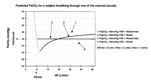
Setting of Pr~C02
Now consider the concentration of COZ which is required in the reserve gas in
order to
provide no ventilation. A mathematical model has been used to calculate the
PaCO~ as a
function of minute ventilation (Figure 6). Note that for each FGF and PrgC02
tested, the
PaC02, as ventilation increases, approaches the PCOZ of the reserve gas. This
indicates that
the appropriate reserve gas concentration is that equal to the desired PaC02.
(curves 3 and 4).
A system of equations below confirms that the reserve gas PCOZ must be equal
to the arterial
PCO2.
CA 02346517 2001-05-04
Page 25
When ventilation approaches infinity, the PCOZ of the gas in the alveoli will
approach the
PrgCOz. Since the PaCOz (for example 40 mmHg) is in equilibrium with the
alveolar PCOZ ,
the PaC02 will approach the PrgCOz which has been set at PvC02 (46 mmHg), and
thus will
not be maintained at initial levels, for example 40 mmHg.
Clearly the PrgC02 cannot be set equal to PvC02. We have determined the PrgC02
should
instead be set equal to PaC02 in order to maintain PaC02 unchanged at all
levels of VE above
resting VE (resting VE). Although Fisher's method works well at low VE, we
offer the
following improvement which works well at all VE, and in so doing provide a
better
explanation of the underlying physiology.
FGF shall equal resting minute ventilation minus anatomical dead space
ventilation (VE -
VDan).
This proof assumes the same circuit described by Fisher, where a flow of fresh
gas with a
PCOZ of 0 is set equal to VErest, and the balance of VE consists of reserve
gas with a PCOZ of
PrgC02. This proof will show that PrgCOz should be equal to PaC02, and not to
PvC02 as
previously approximated in order for PE'rC02 to remain constant for any
increase in VE.
Definitions
PE'rC02 = end tidal partial pressure of carbon dioxide (mmHg)
PrestE'rCOZ = end tidal partial pressure of carbon dioxide (mmHg)
PiC02 = inspired partial pressure of carbon dioxide (mmHg)
Pbar = barometric pressure (mmHg)
VE = minute ventilation (mL/min)
VCOZ = volume of CO~ produced in 1 minute (mL/min)
VrestC02 = volume of COZ produced at rest in 1 minute (mL/min)
VErest = minute ventilation at rest
n = minute ventilation expressed as number of times minute ventilation at rest
n = VE/VErest
therefore VE = n*VErest (1)
CA 02346517 2001-05-04
Page 26
We specify that VCOZ remains at VrestC02, so that
VCOZ = VrestC02
And PETCO~ remains at PrestETC02, so that
PETCOz = PrestETC02
Proof
The difference between inspired and expired PCOZ (as a fraction of the
barometric pressure)
times the ventilation must be equal to the COZ produced by the body in a given
period of time
(for example 1 minute).
(PrestETCO2 - PiCOz)/Pbar * VE = VrestC02 (2)
With Fisher's circuit, inspired PCOZ can be calculated for any n. The inspired
PCOZ is an
average of the PCOZS of the fresh gas (0 mmHg) and the reserve gas (PrgC02),
weighted by
the relative volumes inspired:
PiC02 = (n-1)/n * PrgCOz (3)
e.g. at 4x VErest, inspired PCOZ is 3/4 reserve gas PCO2, because reserve gas
comprises 3/4 of the total gas inspired.
or alternatively,
PiC02 = (n-1)/n * PrgC02 (3)
e.g. at 4x VErest, AVERAGE inspired PCOZ is 3/4 OF THE reserve gas PCO2,
because reserve gas comprises 3/4 of the total gas inspired, WHILE THE
REMAINING 1/4 IS FRESH GAS WHICH HAS A PCO~ OF 0.
Substitution of 1 and 3 into 2 gives
((PETCOZ - (n-1)/n*PrgC02)/Pbar)*n*VErest = VrestCOz
Solving for PrgC02,
PETCOZ - (n-1)/n*PrgC02 = VrestC02*Pbar/(n*VErest)
PETCOz - VrestC02*Pbar/(n*VErest) _ (n-1)/n*PrgCO~
CA 02346517 2001-05-04
Page 27
(PETCOz - VrestCOz*Pbar/(n*VErest))*n/(n-1) = PrgCOz
PrgCOz = (PrestETC02 - VrestC02*Pbar/(n*VErest))*n/(n-1) (4)
Now,
(VCOZ/VE)*Pbar = PrestETC02 (5)
Solving 5 for VE, we obtain,
VE = VCOZ*Pbar/PrestETC02, (6)
Then at VErest,
VErest = VrestC02*Pbar/PrestETC02, ('7)
Substituting 7 into 4, we obtain,
PrgCOz = (PrestETC02 - VrestC02*Pbar/(n*(VrestC02*Pbar/PrestETC02))*n/(n-1)
(8)
Cancelling like terms for numerator and denominator in 8, we obtain
PrgC02 = (PrestETC02 - PrestETCOZ/n)*n/(n-1) (9)
Factoring out PrestETC02 in 9, we obtain
PrgC02 = PrestETCOz*(1 - 1/n)*n/(n-1) (10)
Factoring out n in 10, we obtain
PrgC02 = PrestETC02*((n - 1)/n)*n/(n-1) (11)
Cancelling like terms from 11,
PrgC02 = PrestETC02 (12)
Therefore, the reserve gas PCOz must be equal to the resting end-tidal PCOZ in
order for the
condition to be met of end-tidal PCOz remaining constant with increased VE.
CA 02346517 2001-05-04
Page 28
This provides an additional advantage over Fisher's method, because the
resting PE'rC02 can
be obtained more readily than the PvCO~. To maintain PE'rC02 constant, the
PrgCOz can be
set by simply measuring the concentration of COZ in gas sampled at end-
expiration. If this is
unknown, the PrgCOz can be set equal to the desired PaC02 (for example 40
mmHg). With
higher and higher minute ventilation, the subject's PaC02 will approach the
PrgC02,
whatever it might have been initially. In this situation, preferably, the
fresh gas flow would
also be set equal to the required alveolar ventilation which would produce the
desired arterial
PCO2. This could be empirically determined, or calculated from the alveolar
gas equation.
Therefore, we have shown that in order to make PaC02 independent of minute
ventilation
(Figure 6) FGF should be set substantially equal to baseline minute
ventilation minus
anatomical dead space, and reserve gas PCOZ should be set subtantially equal
to arterial
PCO2.
Eauation
Our new equation more fully and accurately describes what is happening than
that of Fisher.
PvC02 in Fisher's equation has been replaced with PaC02. VE in Fisher's
equation has been
replaced with VE - VDan. Finally, an additional term has been added which
describes the
effect of the alveolar dead space. The alveolar dead space ventilation has the
effect of
decreasing the amount of fresh gas and reserve gas by the proportion of total
ventilation of
the alveolar compartment which it occupies.
Va = 1- VDa'" ~t-~ FGF + ((VE - VD ~- FGF~ ~aC02 - PrgC02
VE - VDa~ ~ PaCO2
Application of circuit to anaesthesia circle circuit
The schematic of the standard anaesthetic circle circuit, spontaneous
ventilation (Figure 2)
When the patient exhales, the inspiratory valve (1) closes, the expiratory
valve (2) opens and
gas flows through the corrugated tubing making up the expiratory limb of the
circuit (3) into
the rebreathing bag (4). When the rebreathing bag is full, the airway pressure-
limiting (APL)
CA 02346517 2001-05-04
Page 29
valve (5) opens and the balance of expired gas exits through the APL valve
into a gas
scavenger (not shown). When the patient inhales, the negative pressure in the
circuit closes
the expiratory valve (2), opens the inspiratory valve (1), and directs gas to
flow through the
corrugated tube making up the inspiratory limb of the circuit (6). Inspiration
draws all of the
gas from the fresh gas hose (7) and makes up the balance of the volume of the
breath by
drawing gas from the rebreathing bag (4). The gas from the rebreathing bag
contains expired
gas with C02 in it. This C02 is extracted as the gas passes through the C02
absorber (8) and
thus is delivered to the patient (P) without CO~, (but still containing
exhaled anaesthetic
vapour, if any).
Modification of the circuit (Figure 3) to allow hyperventilation of patients
under anaesthesia
The modified circuit consists of
1. a circuit which acts functionally like a standard self inflating bag (such
as made by
Laerdal) consisting of
a) a non rebreathing valve, such as valve #560200 made by Laerdal, that
functions during spontaneous breathing as well as manually assisted breathing
(9);
b) an expired gas manifold, such as the Expiratory Deviator #850500, to
collect
expired gas ( 10) and direct it to a gas scavenger system (not shown) or to
the
expiratory limb of the anaesthetic circuit (figure 4);
c) a self inflating bag (11) whose entrance is guarded by a one way valve
directing gas into the self inflating bag ( 12).
2. a source of fresh gas, (i.e. not containing vapour) e.g. oxygen or oxygen
plus nitrous
oxide (13) with a flow meter (22).
3. a manifold ( 14) with 4 ports:
a) a port (15) for input of fresh gas (13);
b) a port ( 16) for a fresh gas reservoir bag ( 17);
c) a port to which is attached a one way inflow valve that opens when the
pressure inside the manifold is Scm H20 less than atmospheric pressure, such
as Livingston Health Care Services part #9005, (18) (assuring that all of the
fresh gas is utilized before opening);
d) a bag of gas ( 19) whose PC02 is equal approximately to that of the
arterial
PC02 connected to inflow valve (18)(Alternatively, the valve and gas
reservoir bag can be replaced by a demand regulator, such as Lifetronix
CA 02346517 2001-05-04
Page 30
MX91120012, similar to that used in SCUBA diving, and a cylinder of
compressed gas);
e) a port to which is attached a one way outflow valve (20), such as
Livingston
Health Care Services catalog part #9005, that allows release of gas from the
manifold to atmosphere when the pressure in the manifold is greater than Scm
H20.
Method of operation in an anaesthetic circuit (Figure 4A)
The distal end of the nonrebreathing valve (Laerdal type) (9), is attached to
the patient.
The proximal port of the nonrebreathing valve is attached to a 3 way
respiratory valve (21 )
which can direct inspiratory gas either from the circle anaesthetic circuit
(Figure 4B) or from
the new circuit (Figure 4C). The expiratory manifold ( 10) of the self
inflating bag's non
rebreathing valve is attached to the expiratory limb of the anaesthetic
circuit (3). Regardless
of the source of inspired gas, exhalation is directed into the expiratory limb
of the anaesthetic
circuit.
To maximize the elimination of anaesthetic vapour from the patient's lungs,
the 3-way
respiratory stopcock is turned such that patient inspiration is from the new
circuit (Figure
4C). Thus inspired gas from the very first breath after turning the 3-way
valve onward
contains no vapour, providing the maximum gradient for anaesthetic vapour
elimination.
An increased breathing rate will further enhance the elimination of vapour
from the lung. If
breathing spontaneously, the patient can be stimulated to increase his minute
ventilation by
lowering the FGF (22) thereby allowing the PC02 to rise. Using this approach
the PC02
will rise and plateau independent of the rate of breathing, resulting in a
constant breathing
stimulus. All of the ventilation is effective in eliminating vapour.
If the patient is undergoing controlled ventilation, he can also be
hyperventilated with the
self inflating bag (11). In either case, the patient's PC02 will be determined
by the FGF
(22). As long as the FGF remains constant, the PC02 will remain constant
independent of
the minute ventilation.
Conventional servo-controlled techniques designed to prevent changes in PC02
with
CA 02346517 2001-05-04
Page 31
hyperpnea are less affected by changes in C02 production than the circuit;
however, they
have other limitations. The assumption that detected changes in PETC02 are due
to a change
in PaC02 is not always warranted (14). Small changes in ventilatory pattern
can 'uncouple'
PETC02 from PaC02, resulting in PE'rC02 being an inappropriate input for the
control of
PaC02. For example, a smaller V'r decreases VA (which tends to increase PaC02)
but will
also decrease PETC02, causing a servo-controller to respond with an
inappropriate increase
in inspired C02 . Even under ideal conditions, a servo-controlled system
attempting to
correct for changes in PETC02 cannot predict the size of an impending V'r in a
spontaneously
breathing subject and thus deliver the appropriate C02 load. If in an attempt
to obtain fme
control the gain in a servo-control system is set too high, the response
becomes unstable and
may result in oscillation of the control variable ( 11 ). Conversely, if the
gain is set too low,
compensation lags (9). Over-damping of the signal results in the response
never reaching the
target. To address these problems, servo-controllers require complex
algorithms ( 16) and
expensive equipment.
When C02 production is constant, the circuit has the theoretical advantage
over servo-
controlled systems in that it provides passive compensation for changes in V.
This
minimizes changes in VA, pre-empting the need for subsequent compensation.
Maintenance
of a nearly constant VA occurs even during irregular breathing, including
brief periods when
V is less than the FGF. Under this circumstance, excess FGF is stored in the
fresh gas
reservoir and subsequently contributes to VA when ventilation exceeds FGF.
When C02 production increases during hyperventilation, as would occur with
increased
work of breathing or exercise, our method requires modification. To
compensate, additional
VA can be provided either by increasing FGF or by lowering the PC02 of the
reserve gas
below the PvC02.
We therefore have described a simple circuit that disassociates VA from V. It
passively
minimizes increases in Va that would normally accompany hyperventilation when
C02
production is constant. It can be modified to compensate for increases in C02
production.
The circuit may form the basis for a simple and inexpensive alternative to
servo-controlled
systems for research and may have therapeutic applications.
CA 02346517 2001-05-04
Page 32
Rebreathing Circuit
Referring to Figure 7, the patient breathes through one port o.f a Y-piece
(1). The other 2
arms of the Y-piece contain 1-way valves. The inspiratory limb of the Y-piece
contains a
one-way valve, the inspiratory valve (2) which directs gas to flow towards the
patient when
the patient makes an inspiratory effort but during exhalation acts as a check
valve preventing
flow in the opposite direction. The other limb of the Y-piece, the expiratory
limb, contains a
one-way valve, the expiratory valve (3), positioned such that it allows gas to
exit the Y-piece
when the patient exhales but acts as a check valve preventing flow towards the
patient when
the patient inhales. Immediately distal to the expiratory limb of the Y-piece
is attached large
bore tubing (4), termed 'reservoir tube' that is open at its distal end (5).
The reservoir tube is
preferably greater than 22 mm in diameter, and its length is such that the
total volume of the
tubing is about or greater than 3L when it is being used for an average (70
Kg) adult. Larger
volumes of reservoir tubing will be required for larger subjects and vice
versa. The
inspiratory port is connected to a source of fresh gas (6) i.e., gas not
containing CO2, flowing
into the circuit at a fixed rate and a fresh gas reservoir bag (9) of about 3L
in volume. A
bypass conduit (7) connects the expiratory limb and the inspiratory limb. The
opening of the
conduit to the expiratory limb is preferably as close as possible to the
expiratory one-way
valve. This conduit contains a one-way valve (8) allowing flow from the
expiratory to the
inspiratory limb. The conduit's one-way valve requires an opening pressure
differential across
the valve slightly greater than that of the inspiratory valve. In this way,
during inspiration,
fresh gas, consisting of fresh gas flow and the contents of the fresh gas
reservoir bag, is
preferentially drawn from the inspiratory manifold.
Circuit function
When the subject's minute ventilation less anatomical dead space is equal to
or less than the
FGF, only fresh gas (FG) is breathed. During exhalation FG accumulates in the
FG reservoir.
During inhalation fresh gas flowing into the circuit and the contents of the
fresh gas reservoir
are inhaled. When minute ventilation less anatomical dead space exceeds FGF,
on each
breath, FG is breathed until the FG reservoir is emptied. Additional
inspiratory efforts result
in a decrease in gas pressure on the inspiratory side of the circuit. When
this pressure
CA 02346517 2001-05-04
Page 33
differential across the bypass conduit's valve exceeds its opening pressure,
the one-way valve
opens and exhaled gas is drawn back from the expired gas reservoir into the
inspiratory limb
of the Y-piece and hence to the patient. The last gas to be exhaled during the
previous breath,
termed 'alveolar gas' is the first to be drawn back into the inspiratory limb
and inhaled
(rebreathed) by the subject.
Method to measure anatomical dead space
We provide a method whereby fresh gas flow can be set equal to the minute
ventilation less
the anatomical dead space ventilation (Vdan). Fresh gas flow should initially
be set
approximately equal to the resting minute ventilation. Fresh gas flow can be
slowly
decreased, for example 200 mL/min at a time. PE'rC02, will remain flat
initially, and at some
point will begin to rise exponentially. This can be seen in Figure 8, in which
a human subject
breathed through the circuit while fresh gas flow was decreased in steps. We
define this point
as the "inflection point". The FGF at the inflection point is equal to VE -
Vdan. It is apparent
that this circuit can therefore be used to measure anatomical dead space as
the difference
between resting ventilation and the inflection point, divided by the
respiratory frequency
Vdan = (VE -- FGF at inflection point), and anatomical dead space = (VE - FGF
at inflection
point)/~ Those skilled in the art will recognize that there are other ways to
use this circuit to
measure dead space for example measuring the resting VE and PE'rC02, asking
the subject to
hyperventilate and then progressively decreasing the fresh gas flow until
resting PETCOZ is
reached. Because the rebreathing circuit taught by Fisher works in the same
way, it too can
be used to measure anatomical dead space in this way. Other variations of
using these circuits
to measure anatomical dead space will be apparent to those skilled in the art.
This method of
measuring anatomical dead space can be used with any circuit where fresh gas
flow limits
alveolar ventilation under the conditions where all fresh gas flow is inhaled
during breathing.
Portable Isocapnia Circuit
Referring to figure 9, the patient breathes through one port of a Y-piece (1).
The other 2 arms
of the Y-piece contain 1-way valves. 'The inspiratory limb of the Y-piece
contains a one-way
valve, the inspiratory valve (2) which directs gas to flow towards the patient
when the patient
makes an inspiratory effort but during exhalation acts as a check valve
preventing flow in the
CA 02346517 2001-05-04
Page 34
opposite direction. The other limb of the Y-piece, the expiratory limb,
contains a one-way
valve, the expiratory valve (3), positioned such that it allows gas to exit
the Y-piece when the
patient exhales but acts as a check valve preventing flow towards the patient
when the patient
inhales. Immediately distal to the expiratory limb of the Y-piece is attached
large bore tubing
termed the 'alveolar gas reservoir'(4), contained in a pliable bag of about 3L
in volume
whose proximal end is sealed around the proximal end of the alveolar gas
reservoir (4) said
bag termed 'expiratory reservoir bag' (5). The expiratory reservoir bag (5)
contains a second
length of tubing termed 'exhaust tubing' (6) with a smaller diameter than the
alveolar gas
reservoir preferably at its distal end where expired gas exits to atmosphere
(7) and is situated
such that most of the tubing is contained within said bag (5) and with said
bag sealed to the
circumference of the tube at its distal end. The alveolar reservoir tube (4)
is preferably about
35 mm in diameter, and its length is such that the total volume of the tubing
is about or
greater than 0.3 L when it is being used for an average (70 Kg) adult. The
expiratory gas
reservoir bag (5) has preferably a capacity of about 3 L. The exhaust tubing
(6) has a
diameter of preferably less than 15 mm at its distal end.
The inspiratory port opens into a cylindrical container composed of a rigid
proximal end plate
(8), a collapsible plicated tube (9) extending distally from the circumference
of the proximal
plate (8) and a rigid plate sealing the distal end of the collapsible plicated
tube ( 10). When
not in use, the tube is kept open by the force of gravity on the distal plate
( 10) andlor by the
force of a spring (11) and/or by intrinsic recoil of the plicated tubing. The
inspiratory port is
open to atmosphere by means of a nozzle (12) to which a length of tubing (13)
is attached.
The distal end plate is open to a nozzle (15) to which a length of tubing (16)
is attached. The
proximal end plate contains a protuberance (16) pointing into the tube that is
aligned with the
internal opening of the distal end plate nozzle (14). The combined proximal
end plate (8),
plieated tubing (9), distal end plate (10) spring (11), inspiratory port
nozzle (12), tubing
attached to inspiratory port nozzle (13), distal end plate nozzle (14), tubing
attached to distal
end plate nozzle (15), proximal end plate protuberance (16) are in aggregate
referred to as the
'atmospheric air aspirator' (AAA). A bypass conduit ( 17) connects the
expiratory limb and
the inspiratory limb. The opening of the conduit to the expiratory limb is
preferably as close
as possible to the expiratory one-way valve. This conduit contains a one-way
valve ( 18)
allowing flow from the expiratory to the inspiratory limb. The conduit's one-
way valve
requires an opening pressure differential across the valve slightly greater
than the pressure
CA 02346517 2001-05-04
Page 35
difference between the inspiratory limb pressure and atmospheric pressure that
is sufficient to
collapse the plicated tube. In this way, during inspiration, atmospheric air
contained in the
atmospheric air aspirator and the air being continuously aspirated into the
inspiratory limb is
preferentially drawn from the inspiratory manifold.
Circuit Function
Assuming initially a version of the circuit without the spring (11), nozzle on
the distal end
plate (14), or internally directed protuberance (16). When the subject begins
to breathe, each
inspiration is drawn initially from the atmospheric air aspirator, collapsing
the plicated tubing
(9) and approximating the distal end plate (10) to the proximal end plate (8).
As long as the
tubing is partially collapsed, there is a constant sub-atmospheric pressure in
the inspiratory
limb of the circuit. Said sub-atmospheric pressure creates a. pressure
gradient drawing
atmospheric air into the inspiratory limb of the circuit through the nozzle
(12) and tubing
(13). When the subject's minute ventilation is equal to or less than the
intended flow of
atmospheric air into the aspirator, only atmospheric air is breathed. During
exhalation
atmospheric air accumulates in the atmospheric air aspirator. During
inhalation inspired gas
consists of the contents of the atmospheric air aspirator and the atmospheric
air flowing into
the inspiratory limb through the nozzle. When minute ventilation exceeds the
net flow of
atmospheric air into the circuit, on each breath, air is breathed until the
atmospheric air
aspirator is collapsed. Additional inspiratory efforts result in an additional
decrease in gas
pressure on the inspiratory side of the circuit. When this pressure
differential across the
bypass conduit's valve exceeds its opening pressure, the one-way valve opens
and exhaled
gas is drawn back from the expired gas reservoir into the inspiratory limb of
the Y-piece and
hence to the patient. To the extent that the opening pressure of the bypass
valve is close to the
pressure generated by the recoil of the atmospheric air aspirator, there will
be little change in
the flow of atmospheric air into the circuit during inspiration after the
atmospheric air
aspirator has collapsed. The last gas to be exhaled during the previous
breath, termed
'alveolar gas' is retained in the alveolar gas reservoir (4) and is the first
gas to be drawn back
into the inspiratory limb of the circuit and inhaled (rebreathed) by the
subject. After several
breaths, the rest of the gas in the expiratory gas reservoir (5) contains
mixed expired gas.
The mixed expired gas from the expired gas reservoir replaces the gas drawn
from the
alveolar gas reservoir and provides the balance of the inspired volume
required to meet the
CA 02346517 2001-05-04
Page 36
inspiratory effort of the patient. The greater restriction in the diameter of
the second tube (6)
than in the alveolar gas reservoir (4) results in the gas being drawn into the
alveolar gas
reservoir being displaced by the collapse of the expired gas reservoir bag in
preference to
drawing air from the ambient atmosphere. The second tube in the expiratory bag
(6) provides
a route for exhaust of expired gas and acts as a reservoir for that volume of
atmospheric air
that diffuses into said expiratory gas reservoir bag through the distal
opening, tending to keep
such atmospheric air separate from the mixed expired gas contained in the
expired gas
reservoir.
During exhalation and all of inhalation until the collapse of the atmospheric
gas aspirator, the
flow of atmospheric air into the circuit will remain constant. However, after
the atmospheric
air aspirator collapses the pressure gradient will increase. The effect of the
increase in total
flow will depend on the difference between the opening pressure of the bypass
valve (18) and
the recoil pressure of the atmospheric air aspirator times the fraction of the
respiratory cycle
when the atmospheric air aspirator is collapsed. If the fraction of the
respiratory cycle when
the atmospheric air aspirator is collapsed is great, as when there is a very
great excess minute
ventilation above the rate of atmospheric air aspiration, the atmospheric air
aspirator can be
modified adding a second port for air entry at, for example, the distal end
plate (14) such that
the total flow from the two ports provides the desired total flow of air into
the circuit under
the recoil pressure of the atmospheric air aspirator. When the atmospheric air
aspirator
collapses on inspiration the second port (14) is occluded by the protuberance
(16), the
remaining port (12) providing a greater resistance to air flow to offset the
greater pressure
gradient being that gradient required to open the bypass valve (18).
The embodiment described above assumes that the force of gravity acting on the
distal plate
provides the recoil pressure to open the atmospheric air aspirator. The
disadvantage to this
configuration is that the distal end plate must be fairly heavy to generate
the sub-atmospheric
pressure. This may be too heavy to be supported by attachment to a face mask
strapped to
the face. Furthermore movement such as walking or running or spasmodic
inhalation will
cause variations in the pressure inside the atmospheric air aspirator and
hence variation in
flow of air into the atmospheric air aspirator. In such cases it is better to
minimize the mass
of the distal endplate and use a different type of motive force to provide
recoil symbolized by
the spring ( 11 ).
CA 02346517 2001-05-04
Page 37
Preferably the circuit as described above is installed in a case to render it
fully portable. The
case may include the appropriate number of capped ports to allow proper set up
and use of
the circuit.
While the foregoing provides detailed descriptions of preferred embodiment of
the invention,
it is to be understood that these descriptions are illustrative only of the
principles of the
invention and not limitative. Furthermore, as many changes can be made to the
invention
without departing from the scope of the invention; it is intended that all
material contained
herein be interpreted as illustrative of the invention and not in a limiting
sense.