Note: Descriptions are shown in the official language in which they were submitted.
CA 02346680 2001-10-26
COATING MACHINE FOR THE UPGRADING OF SHEET MATERIAL
FIELD OF THE INVENTION
The invention relates to a coating machine for upgrading sheet
material by applying a flowable substance thereon.
BACKGROUND OF THE INVENTION
DF 36 19 485 A1 discloses a coating machine which permits the
recessed or full-surface coating of webs or sheets with lacquer. This coating
mechanism essentially consists of a counter-roller functioning as a counter
pressure cylinder, an inking roller standing in contact with the counter-
pressure
cylinder and functioning as a form cylinder, as well as a coating roller
associated with the form cylinder which functions as an inking roller, and an
associated dosing roller.
The coating roller and dosing roller in this machine form a dosing
system (two-roller mechanism) with a roller gap in common. The entry of the
flowable substance, in this case a lacquer, occurs by means of a feed device
feeding lacquer into this roller gap. In the printing gap formed from the
counter-
pressure cylinder and the form cylinder there occurs the full-surface or the
recessed coating of the print material by the lacquer.
A disadvantage with the above arrangement is that the flowable
substance is applicable to the print material only on one side, and that in
the
recessed coating a distribution roller must additionally be allocated to the
application roller
OBJECTS AND SUMMARY OF THE INVENTION
It is an object of the present invention to provide an improved coating
machine which avoids thE: foregoing disadvantages and which has particularly
usage in sheet-fed rotary sprinting presses.
Another object i:> to provide a coating machine that can be operated in
line for one-side (front side) or two-sides (front and back side) coating of
sheet
material. Moreover, during such in line operation, a multiple coating may be
-1-
CA 02346680 2004-12-09
applied on one side or both sides of the sheet material.
A further object is to provide a coating machine that is adapted to
improve the quality of printed sheet material, or even unprinted sheet
material
such as, for example, recycling material.
Yet another object is to provide a modular constructed coating
machine that can be assembled in series. In this regard, simple assembly is
achievable by a coating machine that has, in the conveyance direction of sheet
material, a feeder unit, at least one first coating unit for the front side of
the
sheet material, a turning unit for the sheet material, at least one first
coating unit
for the reverse side of the sheet material, and a delivery unit. As a further
aspect of the invention, second and third coating units for the front side as
well
as, for example second and third coating units for the reverse side of the
sheet
material are possible. All the coating units, furthermore, may have the same
construction. Only the printing forms and the dosing system need be provided
in correspondence to the coating requirement.
Between the coating units for the front side and also for the reverse
side of the sheet material, there is arranged in each case at least one
transfer
drum for the sheet transport, the sheet-turning unit also taking over the
function
of the transfer drum.
In accordance with a first broad aspect of the present invention, there
is provided a coating machine for applying coatings to sheet material as it is
moved in a sheet conveyance direction comprising in the sheet conveyance
direction a first coating unit for applying a flowable coating substance to a
front side of the sheet material, a sheet turning unit for reversing the
position
of the sheet, a first coating unit for applying a flowable coating substance
to a
reverse side of the sheet material, a delivery unit for receiving and
delivering
the coated sheet material, and sheet transfer drums for transferring sheets
between the coating units, the first coating units being of like construction,
each including a printing form carrying form cylinder, a counter pressure
cylinder, and a dosing system having an application roller associated with the
form cylinder.
_2_
CA 02346680 2004-12-09
As a further feature of the invention, the sheet turning unit of a series
constructed coating machine can be switched over in its manner of operation.
Accordingly, the coating machine with its coating units is usable for the one-
side as well as two-side coating of the sheet material.
As a further feature of the invention at least one coating unit for the
front side of the sheet material and at least one coating unit for the reverse
side
of the sheet material, in each case having a counter-pressure cylinder and a
form cylinder, further having exchangeable dosing systems for the processing
of the flowable substances. Preferably, all the coating units have
exchangeable
dosing systems. In that case, the dosing systems are usable in several-coating
units with different and/or the same construction.
More particularly, each dosing system preferably has an application
-2a-
CA 02346680 2001-10-26
roller standing in contact with the form cylinder. The application roller in
the
particular dosing system i:>, at will:
a dosing roller assigned to the formation of a common roller gap, in
which the flowable substance is feedable into this roller gap, or
a wiper arranged with a circulation system having a feed line and
lead-off line for the flowable substance, and in which the application roller
is
screen-gridded, or
a scoop roller arranged in a supply container.
The form cylinder can optionally carry a flexible planographic printing
form, for example a rubber blanket, or a flexible raised printing plate, for
example a flexo print plate. Also UV-resistant flexo-print plates are usable.
The invention is to be explained in detail in an example of execution.
Here, there are schematically shown, in
Fig. 1 a coating machine with two coating units one for the front-
side and one for the reverie side of the sheet material.
Fig. 2 a further development of the coating machine according to
Fig. 1.
In Figs. 1 and 2 there are represented variants of coating machines in
a series-construction manner for inline improvement.
Other objects and advantages of the invention will become apparent
upon reading the following detailed description and upon reference to the
drawings, in which:
BRIEF DESCRIPTION OF THE DRAWINGS
FIG. 1 is a side elevational view of a series constructed coating
machine embodying the present invention; and
FIG. 2 is a side elevational view of an alternative embodiment of
coating machine.
While the invention is susceptible of various modifications and
alternative constructions, certain illustrated embodiments thereof have been
shown in the drawings and will be described below in detail. It should be
-3-
CA 02346680 2001-10-26
understood, however, that there is no intention to limit the invention to the
specific forms disclosed, but on the contrary, the intention is to cover all
modifications, alternative constructions and equivalents falling within the
spirit
and scope of the invention.
DESCRIPTION OF PREFERRED EMBODIMENTS
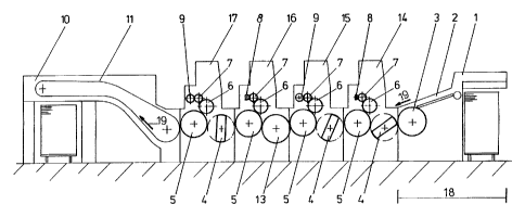
Referring now rnore particularly to FIG. 1 of the drawings, there is
shown an illustrative coating machine embodying the present invention. The
coating machine, in the conveying direction has, in conveyance direction 19 of
the sheet material, a feeder unit 18 which is formed by a feeder 1, a feed
table
2, as well as a contact drum 3. The feeder unit 18 is followed by a first
coating
unit 14 for the sheet fronl: side, as well as by a second coating unit 15 for
the
sheet front side. Between feeder unit 18 and the first coating unit 14, as
well as
between the first and the second coating units 14, 15, there is arranged in
each
case a transfer drum 4 for the sheet transport. After a second coating unit 15
for the sheet front side, inhere is arranged a sheet turning unit 13. After
the
sheet turning unit 13 there follows a first coating unit 16 for the sheet
reverse
side, after this a transfer drum 4, as well as a second coating unit 17 for
the
sheet back side. After thE; second coating unit 17 for the sheet back side,
there
is arranged a delivery unit 10 with revolving conveyance systems 11 for the
purpose of feeding and dE:positing the sheet material onto a delivery stack.
Each of the coating units 14, 15 for the sheet front side, as well as
units 16, 17 for the sheet reverse side, consists, in like construction, of a
counter-pressure cylinder 5, a form cylinder 6 and an application roller 7 as
part
of the dozing system. Prf:ferably--with respect to a single-size form cylinder
6--
the counter-pressure cylinder 5 as well as the transfer drum 4 or a turning
drum
of the sheet turning unit 13, are constructed double-sized in each coating
unit
14-17.
In the first coating unit 14 for the sheet front side, as well as in the first
coating unit 16 for the sheet backside, the dosing system is formed in each
case from a grid-patterned application roller 7, preferably a laser-engraved
-4-
CA 02346680 2001-10-26
ceramic roller, and of a chamber wiper 8 with a conduction-side circulating
system for the flowable substance to be processed. The form cylinders 6 for
the first coating unit 14 for the sheet front side and first coating unit 16
for the
sheet reverse side each carry a flexible raised-print form, for example a
flexo
print plate.
In the second coating unit 15 for the sheet front side, as well as the
second coating unit 17 for the sheet reverse side the dosing system is formed
in each case by the application roller 7 associated with the form cylinder 6
as
well as a dosing roller 9. Application roller 7 and dosing roller 9 form a
roller
gap into which the flowable substance is directly fed from above. The form
cylinder 6 of the second coating units, i.e., 14 for the sheet front side and
16 for
the sheet reverse side, carry in each case a rubber blanker.
The operation of the coating machine illustrated in Fig. 1 is as follows.
The sheet material is fed in conveyance direction 19 by means of feeder unit
18 and transfer drum 4 to the first coating unit 14 for the sheet front side.
In the
contact gap, formed by form cylinder 6 (with flexible raised-print form) and
the
sheet-conducting counter-pressure cylinder 5, there occurs a spot lacquering
(recessed lacquering) onto the front side of the sheet material. In the
contact
gap of the following second coating unit 15 for the sheet front side, formed
by
form cylinder 6 (with rubber blanket) and the sheet-conducting counter-
pressure
cylinder 5 i:here occurs a full-surface lacquering. In both coating units 14,
15
aqueous dispersion lacquers preferably are used as flowable substances.
The sheet is turned over in the sheet turning unit 13 which operates
according to the known principle of rear edge turning, in which the rear edge
of
the sheet material resting on a sheet-conducting cylinder (counter-pressure
cylinder 5) is grasped by sheet takeover systems, for example suction systems
and gripper systems of the subordinate sheet turning unit 13 and then further
transported in conveyance direction 19. It will be understood that operation
of
the sheet turning unit 13 c:an be switched over, so that so that it carries
out the
function of the transfer drum 4 in one-sided coating. The sheet turning unit
13
is preferably constructed as a single-drum turning, or as a multiple-drum
turning
-5-
CA 02346680 2001-10-26
unit with at least one storage drum arranged in front of the turning drum.
Following the sheet turning unit 13 is the first coating unit 16 for the sheet
reverse side. In its contact gap, formed by form cylinder 6 (with flexible
raised
print form) .and the sheet-conducting counter-pressure cylinder 5, there
occurs
spot lacquering (recessed lacquering) on the back side of the sheet material.
In
the contact gap of the following second coating unit 17 of the reverse side,
formed by the form cylinder 6 (with rubber blanket) and by the sheet-
conducting
counter-pressure cylinder 5, there occurs a full-surface lacquering.
In both coating units 16, 17 aqueous dispersion lacquers preferably
are used as flowable substances. After the evaporation of the water in the
dispersion lacquer, a resistant, closed coating exits on the sheet surface.
l/Vhile the illustrated coating machine is operable for two-sided coating
(front/reverse sides) of heet material, alternatively the machine can be
operated for one sided-coating of the sheet material. For this--depending on
the side of the sheet material to be printed--the first and second coating
units
14, 15 for the sheet front ride is activated if the front side of the print
material is
to be coated. The sheet-turning unit 13 then operates and functions as
transfer
drum 4 (without sheet turning) and the subsequent coating units 16, 17 for the
sheet reverse side are inactive; i.e. they do not participate in the coating
operation, nor undertake further coatings on one side of the sheet material.
If the back side of the sheet material is to be coated on one side, then
the first and second coating units 14, 15 for the sheet front side 15, 16 are
inactive (not participating in the coating operation). The sheet-conducting
cylinders (i.e., counter-pressure cylinder 5, transfer drum 4) conduct the
sheet
material to the sheet turning unit 13. The sheet turning unit 13 turns the
sheet
material and the subsequent first and second coating units 16, 17 for the
sheet
reverse side are activated and carry out the corresponding coatings.
An alternative ernbodiment of coating machine is illustrated in Fig. 2,
wherein the first coating unit 14 for the sheet front side is constructed and
operates similar to the first coating unit 14 in the previously disclosed
embodiment of Fig. 1. In the second coating unit 15 for the sheet front side,
the
-6-
CA 02346680 2001-10-26
contact roller 7 (from Fig. 1 ) is exchanged for a contact roller 8 with a
grid-
patterned structure (Fig. 2), and the dosing roller 9 (from Fig. 1 ) is
exchanged
for a chamber wiper 8 (Fiq. 2). In the first coating unit 16 for the sheet
reverse
side, the patterned application (contact) roller 7 (Fig. 1 ) is exchanged for
an
application roller (Fig. 2) with lower surface hardness than the patterned
application roller. The chamber wiper (Fig. 1 ) is exchanged for a dosing
roller 9
with higher surface hardness than the application roller 7. The dosing roller
9
as well as the application (contact) roller 7 are preferably exchangeable
among
one another in their bearing locations in all of the coating units 14-17.
The dosing system formed from patterned application (contact) roller
7 and the chamber wiper 8 is suited in this construction for the improving of
the
sheet material with dispersion lacquer, or UV-lacquer, or flexo-printing
paint. In
the processing of dispersion lacquer the form cylinder 6 carries a rubber
blanket
or, in the processing of dispersion lacquer for flexo-print paint, it carries
a
flexible raised-print plate. In the processing of UV-lacquer, a UV-resistant
flexible raised-print plate is arranged on the form cylinder 6.
Between the first coating unit 14 for the sheet front side and the
second coating unit 15 for the sheet front side there is formed a first dryer
module, which includes a transfer drum 4 and a counter-pressure cylinder 5, as
well as a dryer system 12 associated with to the counter-pressure cylinder 5.
In
conveyance direction 19 following the second coating unit 15 for the sheet
front
side, a second dryer module, formed from transfer drum 4, counter-pressure
cylinder 5 as well as a further dryer system 12. After the second dryer module
there follows a sheet turning unit 13 as well as the first coating unit 16 for
the
sheet reverse side. Upon this coating unit 16 for the sheet reverse side there
follows, in like construction, a third dryer module, following which is the
second
coating unit 17 for the sheet reverse side.
The patterned application (contact) roller 7 as well as the chamber
wiper 8 (a<:cording to Fig. 1 ) are exchanged for an application roller 7 and
a
dosing roller 9. The form cylinder 6 carries a rubber blanket for full-surface
or
for recessed lacquering.
-7-
CA 02346680 2001-10-26
According to an extremely simple embodiment, the coating machine
can be constructed in the conveyance direction 19 with the feeder unit 18,
only
one first coating unit 14 for the sheet front side, a sheet turning unit 13,
only the
first coating unit 16 for the sheet reverse side, and an ultimate delivery
unit 10,
the coating elements 14, 16 being of like construction.
A series constructed coating machine may be simply achieved, in the
conveying direction 19 by the feeder unit 18, at least the first coating unit
14 for
the sheet front side follov~red by the sheet turning unit 13, the first
coating unit
16 for the sheet reverse side, and the delivery unit 10.
Optionally, there can additionally be arranged further coating units 14-
17 for the sheet front siderand/or the sheet reverse side, as shown for
example,
in Figs. 1 and 2.
A further construction may be characterized by the first coating unit 14
for the sheet front side having as dosing system with an application roller 7
and
a dosing roller 9 with common roller gap and a feed unit supplying the
flowable
substance from above. The form cylinder 6 in this case carries a rubber
blanket, so that a full-surface coating of the sheet material is achieved. The
second coating unit 15 for' the sheet front side has a patterned application
roller
with an associated chamber wiper 8. In this instance, the form cylinder 6
carries
a flexible raised-print plate so that a recessed coating (spot coating) is
achievable. By means of this spot coating a "floating" coating is achieved on
the previously applied full-surface one-side coating (in this case on the
sheet
front side.).
The foregoing working principle is suited, for example, for the
embedding of certain effects into the already performed full- surface coating
or
for the improvement of the lustre. In a further development, this working
principle is applicable in the first and second coating units 16, 17 for the
sheet
reverse side, in which case the sheet turning unit 13 for the sheet material
first
is passed. In this instance, the first coating unit 16 for the sheet reverse
side is
constructed similarly to the above-described first coating unit 14 for the
front
side, and the second coating unit 17 for the sheet back side is constructed
_g-
CA 02346680 2001-10-26
similarly to 'the above-described second coating unit 15 for the sheet front
side.
Since the dosing systems are exchangeable among one another, after a brief
refitting a construction of the coating machine again is achievable, for
example,
according to Fig. 1.
A further embodiment is achievable when the first coating unit 14 for
the front side has a dosing system that includes a patterned application
roller 7
with allocated chamber wiper 8. The form cylinder 6 carries a flexible raised-
print form. The second coating unit 15 for the sheet front side has a dosing
system that includes an application (contact) roller 7 and a dosing roller 9
with a
common roller gap, in which the form cylinder 6 carries a rubber blanket.
Following the second coating unit 15 for the sheet front side, there may be a
third coating unit for the sheet front side (not shown). This coating unit has
a
counter-pressure cylinder 6 as well as a patterned application (contact)
roller 7
with an allocated chamber wiper 8. In this construction, in the first coating
unit
14 there occurs a spot coating, in the second coating unit 15 a full-surface
coating, and in the third coating unit a renewed spot lacquering for the
"floating"
coating, for example, in effect lacquering into the full-surface coating. This
working principle is likewise applicable for the first and second coating
units 16,
17 for the sheet reverse side (not shown). The first and second coating units
16, 17 as well as the third coating unit for the sheet reverse side are
constructed similarly to the first and second coating units 14, 15 as well as
the
third coating unit for the sheet front side.
Depending on the flowable substance to be processed, dryer modules
may be provided in the above-mentioned embodiments of the coating machine,
especially between the coating units 14-17. Each dryer module includes a
transfer drum 4 and an after-engaged counter-pressure cylinder 5 with an
associated dryer system 12. The elements for the sheet conduction, as well as
the requisite washing dE:vices, for example, for the form cylinder, will be
understood by a person skilled in the art and will not be described in detail.
It will be understood herein that each form cylinder 6 can optionally
carry different printing forims, for example a flexible flat print form or a
flexible
_g_
CA 02346680 2001-10-26
raised print form, as the coating form. The dosing systems need not be
restricted to a patterned application (contact) roller 7 with chamber wiper 8
or
application roller 8, and dosing roller 9. On the contrary, alternative dosing
systems can be used. For example, a substance scooping roller plunging into
a container of the flowablE: material and an associated dosing application
roller,
may be used as dosing system, in which the application roller is allocated to
the
form cylinder 6. To this acooping roller mechanism there can additionally be
allocated a dosing roller. Independently from the particular coating units 14-
17,
the dosing systems are interchangeable among one another. The number of
coating units 14, 15 in front of the sheet-turning unit 13 also can be set
equal to
the coating units 16, 17, or unequal thereto.
-10-
CA 02346680 2001-10-26
[List of reference numbers ]
1. Feeder
2. Feed table
3 Application (contact drum)
4 Transfer drum
5 Counter-pressure cylinder
6 Form cylinder
7 Application roller
8 Chamber wiper
9 Dosing roller
10 Delivery unit
11 Conveyance system
13 Dryer system
13 Sheet turning unit
14 First coating unit for the sheet
front side
15 Second coating unit for the sheet
front side
16 First coating unit for the sheet
reverse side
17 Second coating unit for the sheet
reverse side
18 Feeder unit
19 Conveyance dirE:ction
-11-