Language selection

Search

Patent 2346815 Summary

Third-party information liability

Some of the information on this Web page has been provided by external sources. The Government of Canada is not responsible for the accuracy, reliability or currency of the information supplied by external sources. Users wishing to rely upon this information should consult directly with the source of the information. Content provided by external sources is not subject to official languages, privacy and accessibility requirements.

Claims and Abstract availability

Any discrepancies in the text and image of the Claims and Abstract are due to differing posting times. Text of the Claims and Abstract are posted:

  • At the time the application is open to public inspection;
  • At the time of issue of the patent (grant).
(12) Patent Application: (11) CA 2346815
(54) English Title: VARIABLE CROSS-CUTTING DEVICE
(54) French Title: DISPOSITIF DE COUPE TRANSVERSALE VARIABLE
Status: Deemed Abandoned and Beyond the Period of Reinstatement - Pending Response to Notice of Disregarded Communication
Bibliographic Data
(51) International Patent Classification (IPC):
  • B26D 7/26 (2006.01)
  • B26D 1/40 (2006.01)
(72) Inventors :
  • WITTMAIER, KLAUS (Germany)
(73) Owners :
  • SCHOBER GMBH WERKZEUG- UND MASCHINENBAU
(71) Applicants :
  • SCHOBER GMBH WERKZEUG- UND MASCHINENBAU (Germany)
(74) Agent: GOWLING WLG (CANADA) LLP
(74) Associate agent:
(45) Issued:
(86) PCT Filing Date: 1999-09-17
(87) Open to Public Inspection: 2000-04-20
Availability of licence: N/A
Dedicated to the Public: N/A
(25) Language of filing: English

Patent Cooperation Treaty (PCT): Yes
(86) PCT Filing Number: PCT/EP1999/006889
(87) International Publication Number: WO 2000021723
(85) National Entry: 2001-12-13

(30) Application Priority Data:
Application No. Country/Territory Date
198 46 864.4 (Germany) 1998-10-12

Abstracts

English Abstract


The invention relates to a cutting device, especially a
cross-cutting device for continuous webs, comprising a
transportation device (2) for the continuous web, a cross-
cutting knife (4) and a counter-pressure tool (3). The cross-
cutting knife (4) is sword-shaped and the counter-pressure
tool (3) is a cylinder which interacts with the cross-cutting
knife (4), or a counter-cutting rail. The counter-pressure
cylinder or counter-cutting rail and the cross-cutting knife
accommodate the continuous web between them.


French Abstract

L'invention concerne un dispositif de coupe, notamment un dispositif de coupe transversale pour bandes continues, qui comprend un dispositif transporteur (2) destiné à la bande continue, une lame de coupe transversale (4) et un outil de contre-pression (3). La lame de coupe transversale (4) est en forme de lance. L'outil de contre-pression (3) est un cylindre coopérant avec ladite lame (4) ou une barre de contre-coupe. La bande continue passe entre ledit cylindre ou ladite barre et la lame (4).

Claims

Note: Claims are shown in the official language in which they were submitted.

7
Claims
1. Cutting device, in particular cross-cutting device for
continuous sheets, comprising a transportation device for
the continuous sheet, a cross-cutting knife and a
counter-pressure tool, wherein the cross-cutting knife
has the shape of a sword, characterized in that the
counter-pressure tool is a cylinder cooperating with the
cross-cutting knife, or a counter-cutting rail, on which
the continuous sheet seats and the continuous sheet is
accommodated between the counter-pressure cylinder or the
counter-cutting rail and the cross-cutting knife and a
control device, in particular a servo motor, is provided
for driving the cross-cutting knife which drives the
cross-cutting device at a variable speed, wherein the
cross-cutting knife has a plurality of holes, in
particular transverse bores, extending transverse to the
longitudinal axis.
2. Cutting device according to claim 1, characterized in
that the counter-pressure cylinder or the counter-cutting
rail can be height-adjusted but is rigidly positioned
after adjustment.
3. Cutting device according to claim 1 or 2, characterized
in that the counter-pressure cylinder is disposed in a
rotary fashion.

8
4. Cutting device according to any one of the preceding
claims, characterized by sensors for register markings
provided on the continuous sheet.
5. Cutting device according to claim 4, characterized in
that the control device can be controlled via the
sensors.
6. Cutting device according to any one of the preceding
claims, characterized in that the cross-cutting knife
comprises a quick-connect means for mounting the cutting
knife or perforation knife.
7. Cutting device according to any one of the preceding
claims, characterized in that the cross-cutting knife is
rounded or trapezoidal at its radially inward regions
between the cutting edges or is provided with an edge.

Description

Note: Descriptions are shown in the official language in which they were submitted.


CA 02346815 2001-12-13
3962 135
V,~riab:le Cros s--Cutting Device
Translation of PC~'/EP99/06889 as amended on October 19, 2000
Description
The invention concerns a cross-cutting device having the
features of the pre-characterizing part of claim 1.
According to prior art, different length sections of
continuous material or material sheets have been produced
using formatted cylinders of different sizes having a certain
number of knives disposed on the periphery of these formatted
cylinders. It was thus possible to cut, with one cylinder
having a circumference of 24" (inch), either one 24" length,
two 12" lengths, three 8" lengths, four 6'° lengths or six 4"
lengths. The cross-perforation or cross-c~.ztting means were
therefore dependent on the format of the mounted cylinder and
also on the previously selected format, e.g. inch or mm.
Also known is the use of suitable motor power to accelerate
or decelerate cross-cut~ing devices to produce sections of
different length. EIowever, the variability of these cross-
Gutters was inadequate since the motors required extremely
high drive and delay power and were thereby inaccurate which

CA 02346815 2001-12-13
2
CA-A1-2,176,282 discloses a cro;;s-cutting device on which the
present invention i.s based. This; cross-cutting device is of
very complicated cvonstx:uction and is therefore expensive.
The cross-cutting device in accordance w=ith the present
invention according to the features of claim 1 is of
relatively simple construction, :since the counter-pressure
tool i:~ a simple cylinder or a. counter-cutting rail.
A variable cross-c.~utter in accordance with the invention
which fulfils all the technical requirements and which is
inexpensive to prc~duc:e, is deseri.bed below.
In detail, the cross-cutting device consists of the following
components:
1. Unit frame / housing
The frame structure of the cross-cutting device may be
produced from various materials (aluminum, cast steel, steel,
etc.). The construction details of this frame depend on the
corresponding material sheet width, the diameter of the
rollers and other factors. The frame merely serves to
accommodate the elementa described below.
2. Feed rollers

CA 02346815 2001-12-13
3
The feed roller pair must draw a material or material sheet
into the unit and may either be directly mounted on and also
driven by the cross-cutting means, may be separately mounted
in front of it, ox~ may be part of an already existing
component. This device should draw the material into the
cross-cutting means at a constants or variable speed. A
register control may irufluence the feed station if registered
accurate cross-cutting or perforation of printed material
sheets is required.
3. Counter-pressure cylinder
The counter-pressure cylinder serves as abutment for the
cutting or perforating knife when the material sheet is cut.
It is usually a very precisely disposed counter-pressure
cylinder which is either made from hardened steel or another
hard material or provided with exchangeable hardened rails.
The surface speed or rotational speed of the counter-pressure
cylinder is adjusted to the material sheet arid, if required,
can be driven by an optional base machine.
Instead of the counter-pressure cylinder, a counter-cutting
rail may be used for cooperating with the cross-cutting
knife.
4. Cross-cutting rotor (cross-cutting knife?

CA 02346815 2001-12-13
lines of all kind:. In the preferred embodiment, cross-
cutting knives arf: mounted using a quick-connect means. Other
fastening means ar-e also possible. It is, however, important
that this cross-c~itting rotor and the quick-connect rail
permit rapid replacement of perforation lines and cutting
knives. This reprE:sents a clear advantage over existing
systems.
The cross-cutting rotor has its own electric-motor drive
(servo motor? and comprises a con~ro7_ for controlling the
rotational speed of the rotor. In the present embodiment, the
rotor itself is px°ovided with on7_y one or a maximum of two
knives. Other embodiments may also comprise more knives. Due
to acceleration arcd delay with respect to the material sheet,
different section lengths can be cut or perforated.
The cross-cutting rotor must only assume the speed of the
material sheet within a range of ~10° about the cutting
point. It may othErwise have a slower or faster
circumferential speed compared to that of the material sheet,
to produce the actual material sheet length.
As indicated in figure 1, the cross-cutting rotor has a
particularly important special outer shape. In contrast to
the previous round cutting cylinders, the cross-cutting rotor
has a particularly favorable and suitable shape. This has
several advantages. In particular, the large cross-cutting

CA 02346815 2001-12-13
The second advantage i~: the fact that considerable mass is
saved through omission of the remaining parts in regions
differing from the normal circular shape.
Compared with othE~r structures, the special rotor shape
advantageously has a high bending strength moment, while
being light-weight. Moreover, in dependence on the structure
width "X" , on the thickness of the material, and the
insertion angle of the knife, the depth of insertion into the
material sheet cari advantageously also be varied. The cutting
rotor is thereby also suitable for cutting thick material
sheets.
It is furthermore important that. the rotor has side flanks,
either rounded as shown with 6, planar side flanks as shown
with 7, or sharp ones as shown with 8.
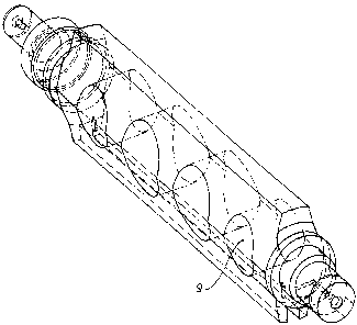
Figure 2 shows an advantageous embodiment. of the cross-
cutting rotor which includes yet one further substantial
advantage. As is evident from Fig. 1, one can expect that
operation of the rotor 'gill be associated with displacement
of an amount of air which is substantially more than that
displaced by a normal r:~und roller. The associated air
resistance acts in opposition to the drive power. This effect
is also unfavorable for further processing of material sheets
or cut sheets and j~an be irritating for the staff. To

CA 02346815 2001-12-13
transverse to its longitudinal axis. These transverse bores
considerably reduc°.e the displacement of air. The introduction
of these transverse bores has the substantial further
advantage that the- mass is also considerably reduced.

Representative Drawing
A single figure which represents the drawing illustrating the invention.
Administrative Status

2024-08-01:As part of the Next Generation Patents (NGP) transition, the Canadian Patents Database (CPD) now contains a more detailed Event History, which replicates the Event Log of our new back-office solution.

Please note that "Inactive:" events refers to events no longer in use in our new back-office solution.

For a clearer understanding of the status of the application/patent presented on this page, the site Disclaimer , as well as the definitions for Patent , Event History , Maintenance Fee  and Payment History  should be consulted.

Event History

Description Date
Application Not Reinstated by Deadline 2003-09-17
Time Limit for Reversal Expired 2003-09-17
Deemed Abandoned - Failure to Respond to Maintenance Fee Notice 2002-09-17
Inactive: Office letter 2002-03-19
Inactive: Correspondence - Formalities 2001-12-13
Letter Sent 2001-11-08
Inactive: Entity size changed 2001-11-07
Reinstatement Requirements Deemed Compliant for All Abandonment Reasons 2001-10-25
Deemed Abandoned - Failure to Respond to Maintenance Fee Notice 2001-09-17
Letter Sent 2001-08-24
Inactive: Cover page published 2001-07-13
Inactive: Correspondence - Transfer 2001-07-10
Inactive: First IPC assigned 2001-06-21
Inactive: Courtesy letter - Evidence 2001-06-19
Inactive: Notice - National entry - No RFE 2001-06-13
Application Received - PCT 2001-06-09
Inactive: Single transfer 2001-06-08
Application Published (Open to Public Inspection) 2000-04-20

Abandonment History

Abandonment Date Reason Reinstatement Date
2002-09-17
2001-09-17

Maintenance Fee

The last payment was received on 2001-08-15

Note : If the full payment has not been received on or before the date indicated, a further fee may be required which may be one of the following

  • the reinstatement fee;
  • the late payment fee; or
  • additional fee to reverse deemed expiry.

Please refer to the CIPO Patent Fees web page to see all current fee amounts.

Fee History

Fee Type Anniversary Year Due Date Paid Date
Basic national fee - standard 2001-04-09
Registration of a document 2001-04-09
MF (application, 2nd anniv.) - standard 02 2001-09-17 2001-08-15
Reinstatement 2001-10-25
Reinstatement (national entry) 2001-12-13
Owners on Record

Note: Records showing the ownership history in alphabetical order.

Current Owners on Record
SCHOBER GMBH WERKZEUG- UND MASCHINENBAU
Past Owners on Record
KLAUS WITTMAIER
Past Owners that do not appear in the "Owners on Record" listing will appear in other documentation within the application.
Documents

To view selected files, please enter reCAPTCHA code :


To view images, click a link in the Document Description column. To download the documents, select one or more checkboxes in the first column and then click the "Download Selected in PDF format (Zip Archive)" or the "Download Selected as Single PDF" button.

List of published and non-published patent-specific documents on the CPD .

If you have any difficulty accessing content, you can call the Client Service Centre at 1-866-997-1936 or send them an e-mail at CIPO Client Service Centre.


Document
Description 
Date
(yyyy-mm-dd) 
Number of pages   Size of Image (KB) 
Representative drawing 2001-07-11 1 13
Cover Page 2001-07-11 1 40
Description 2001-12-13 6 177
Abstract 2001-12-13 1 16
Claims 2001-12-13 2 54
Drawings 2001-12-13 2 38
Reminder of maintenance fee due 2001-06-13 1 112
Notice of National Entry 2001-06-13 1 194
Courtesy - Certificate of registration (related document(s)) 2001-08-24 1 136
Courtesy - Abandonment Letter (Maintenance Fee) 2001-11-07 1 183
Notice of Reinstatement 2001-11-08 1 171
Courtesy - Abandonment Letter (Maintenance Fee) 2002-10-15 1 179
Correspondence 2001-06-13 1 24
PCT 2001-04-09 14 612
PCT 2001-04-10 7 282
Correspondence 2001-12-13 1 39
Correspondence 2002-03-14 1 19
Fees 2001-08-15 1 24
Fees 2001-10-25 2 69