Sélection de la langue

Search

Sommaire du brevet 2346815 

Énoncé de désistement de responsabilité concernant l'information provenant de tiers

Une partie des informations de ce site Web a été fournie par des sources externes. Le gouvernement du Canada n'assume aucune responsabilité concernant la précision, l'actualité ou la fiabilité des informations fournies par les sources externes. Les utilisateurs qui désirent employer cette information devraient consulter directement la source des informations. Le contenu fourni par les sources externes n'est pas assujetti aux exigences sur les langues officielles, la protection des renseignements personnels et l'accessibilité.

Disponibilité de l'Abrégé et des Revendications

L'apparition de différences dans le texte et l'image des Revendications et de l'Abrégé dépend du moment auquel le document est publié. Les textes des Revendications et de l'Abrégé sont affichés :

  • lorsque la demande peut être examinée par le public;
  • lorsque le brevet est émis (délivrance).
(12) Demande de brevet: (11) CA 2346815
(54) Titre français: DISPOSITIF DE COUPE TRANSVERSALE VARIABLE
(54) Titre anglais: VARIABLE CROSS-CUTTING DEVICE
Statut: Réputée abandonnée et au-delà du délai pour le rétablissement - en attente de la réponse à l’avis de communication rejetée
Données bibliographiques
(51) Classification internationale des brevets (CIB):
  • B26D 7/26 (2006.01)
  • B26D 1/40 (2006.01)
(72) Inventeurs :
  • WITTMAIER, KLAUS (Allemagne)
(73) Titulaires :
  • SCHOBER GMBH WERKZEUG- UND MASCHINENBAU
(71) Demandeurs :
  • SCHOBER GMBH WERKZEUG- UND MASCHINENBAU (Allemagne)
(74) Agent: GOWLING WLG (CANADA) LLP
(74) Co-agent:
(45) Délivré:
(86) Date de dépôt PCT: 1999-09-17
(87) Mise à la disponibilité du public: 2000-04-20
Licence disponible: S.O.
Cédé au domaine public: S.O.
(25) Langue des documents déposés: Anglais

Traité de coopération en matière de brevets (PCT): Oui
(86) Numéro de la demande PCT: PCT/EP1999/006889
(87) Numéro de publication internationale PCT: WO 2000021723
(85) Entrée nationale: 2001-12-13

(30) Données de priorité de la demande:
Numéro de la demande Pays / territoire Date
198 46 864.4 (Allemagne) 1998-10-12

Abrégés

Abrégé français

L'invention concerne un dispositif de coupe, notamment un dispositif de coupe transversale pour bandes continues, qui comprend un dispositif transporteur (2) destiné à la bande continue, une lame de coupe transversale (4) et un outil de contre-pression (3). La lame de coupe transversale (4) est en forme de lance. L'outil de contre-pression (3) est un cylindre coopérant avec ladite lame (4) ou une barre de contre-coupe. La bande continue passe entre ledit cylindre ou ladite barre et la lame (4).


Abrégé anglais


The invention relates to a cutting device, especially a
cross-cutting device for continuous webs, comprising a
transportation device (2) for the continuous web, a cross-
cutting knife (4) and a counter-pressure tool (3). The cross-
cutting knife (4) is sword-shaped and the counter-pressure
tool (3) is a cylinder which interacts with the cross-cutting
knife (4), or a counter-cutting rail. The counter-pressure
cylinder or counter-cutting rail and the cross-cutting knife
accommodate the continuous web between them.

Revendications

Note : Les revendications sont présentées dans la langue officielle dans laquelle elles ont été soumises.


7
Claims
1. Cutting device, in particular cross-cutting device for
continuous sheets, comprising a transportation device for
the continuous sheet, a cross-cutting knife and a
counter-pressure tool, wherein the cross-cutting knife
has the shape of a sword, characterized in that the
counter-pressure tool is a cylinder cooperating with the
cross-cutting knife, or a counter-cutting rail, on which
the continuous sheet seats and the continuous sheet is
accommodated between the counter-pressure cylinder or the
counter-cutting rail and the cross-cutting knife and a
control device, in particular a servo motor, is provided
for driving the cross-cutting knife which drives the
cross-cutting device at a variable speed, wherein the
cross-cutting knife has a plurality of holes, in
particular transverse bores, extending transverse to the
longitudinal axis.
2. Cutting device according to claim 1, characterized in
that the counter-pressure cylinder or the counter-cutting
rail can be height-adjusted but is rigidly positioned
after adjustment.
3. Cutting device according to claim 1 or 2, characterized
in that the counter-pressure cylinder is disposed in a
rotary fashion.

8
4. Cutting device according to any one of the preceding
claims, characterized by sensors for register markings
provided on the continuous sheet.
5. Cutting device according to claim 4, characterized in
that the control device can be controlled via the
sensors.
6. Cutting device according to any one of the preceding
claims, characterized in that the cross-cutting knife
comprises a quick-connect means for mounting the cutting
knife or perforation knife.
7. Cutting device according to any one of the preceding
claims, characterized in that the cross-cutting knife is
rounded or trapezoidal at its radially inward regions
between the cutting edges or is provided with an edge.

Description

Note : Les descriptions sont présentées dans la langue officielle dans laquelle elles ont été soumises.

CA 02346815 2001-12-13
3962 135
V,~riab:le Cros s--Cutting Device
Translation of PC~'/EP99/06889 as amended on October 19, 2000
Description
The invention concerns a cross-cutting device having the
features of the pre-characterizing part of claim 1.
According to prior art, different length sections of
continuous material or material sheets have been produced
using formatted cylinders of different sizes having a certain
number of knives disposed on the periphery of these formatted
cylinders. It was thus possible to cut, with one cylinder
having a circumference of 24" (inch), either one 24" length,
two 12" lengths, three 8" lengths, four 6'° lengths or six 4"
lengths. The cross-perforation or cross-c~.ztting means were
therefore dependent on the format of the mounted cylinder and
also on the previously selected format, e.g. inch or mm.
Also known is the use of suitable motor power to accelerate
or decelerate cross-cut~ing devices to produce sections of
different length. EIowever, the variability of these cross-
Gutters was inadequate since the motors required extremely
high drive and delay power and were thereby inaccurate which

CA 02346815 2001-12-13
2
CA-A1-2,176,282 discloses a cro;;s-cutting device on which the
present invention i.s based. This; cross-cutting device is of
very complicated cvonstx:uction and is therefore expensive.
The cross-cutting device in accordance w=ith the present
invention according to the features of claim 1 is of
relatively simple construction, :since the counter-pressure
tool i:~ a simple cylinder or a. counter-cutting rail.
A variable cross-c.~utter in accordance with the invention
which fulfils all the technical requirements and which is
inexpensive to prc~duc:e, is deseri.bed below.
In detail, the cross-cutting device consists of the following
components:
1. Unit frame / housing
The frame structure of the cross-cutting device may be
produced from various materials (aluminum, cast steel, steel,
etc.). The construction details of this frame depend on the
corresponding material sheet width, the diameter of the
rollers and other factors. The frame merely serves to
accommodate the elementa described below.
2. Feed rollers

CA 02346815 2001-12-13
3
The feed roller pair must draw a material or material sheet
into the unit and may either be directly mounted on and also
driven by the cross-cutting means, may be separately mounted
in front of it, ox~ may be part of an already existing
component. This device should draw the material into the
cross-cutting means at a constants or variable speed. A
register control may irufluence the feed station if registered
accurate cross-cutting or perforation of printed material
sheets is required.
3. Counter-pressure cylinder
The counter-pressure cylinder serves as abutment for the
cutting or perforating knife when the material sheet is cut.
It is usually a very precisely disposed counter-pressure
cylinder which is either made from hardened steel or another
hard material or provided with exchangeable hardened rails.
The surface speed or rotational speed of the counter-pressure
cylinder is adjusted to the material sheet arid, if required,
can be driven by an optional base machine.
Instead of the counter-pressure cylinder, a counter-cutting
rail may be used for cooperating with the cross-cutting
knife.
4. Cross-cutting rotor (cross-cutting knife?

CA 02346815 2001-12-13
lines of all kind:. In the preferred embodiment, cross-
cutting knives arf: mounted using a quick-connect means. Other
fastening means ar-e also possible. It is, however, important
that this cross-c~itting rotor and the quick-connect rail
permit rapid replacement of perforation lines and cutting
knives. This reprE:sents a clear advantage over existing
systems.
The cross-cutting rotor has its own electric-motor drive
(servo motor? and comprises a con~ro7_ for controlling the
rotational speed of the rotor. In the present embodiment, the
rotor itself is px°ovided with on7_y one or a maximum of two
knives. Other embodiments may also comprise more knives. Due
to acceleration arcd delay with respect to the material sheet,
different section lengths can be cut or perforated.
The cross-cutting rotor must only assume the speed of the
material sheet within a range of ~10° about the cutting
point. It may othErwise have a slower or faster
circumferential speed compared to that of the material sheet,
to produce the actual material sheet length.
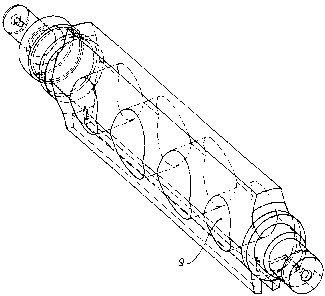
As indicated in figure 1, the cross-cutting rotor has a
particularly important special outer shape. In contrast to
the previous round cutting cylinders, the cross-cutting rotor
has a particularly favorable and suitable shape. This has
several advantages. In particular, the large cross-cutting

CA 02346815 2001-12-13
The second advantage i~: the fact that considerable mass is
saved through omission of the remaining parts in regions
differing from the normal circular shape.
Compared with othE~r structures, the special rotor shape
advantageously has a high bending strength moment, while
being light-weight. Moreover, in dependence on the structure
width "X" , on the thickness of the material, and the
insertion angle of the knife, the depth of insertion into the
material sheet cari advantageously also be varied. The cutting
rotor is thereby also suitable for cutting thick material
sheets.
It is furthermore important that. the rotor has side flanks,
either rounded as shown with 6, planar side flanks as shown
with 7, or sharp ones as shown with 8.
Figure 2 shows an advantageous embodiment. of the cross-
cutting rotor which includes yet one further substantial
advantage. As is evident from Fig. 1, one can expect that
operation of the rotor 'gill be associated with displacement
of an amount of air which is substantially more than that
displaced by a normal r:~und roller. The associated air
resistance acts in opposition to the drive power. This effect
is also unfavorable for further processing of material sheets
or cut sheets and j~an be irritating for the staff. To

CA 02346815 2001-12-13
transverse to its longitudinal axis. These transverse bores
considerably reduc°.e the displacement of air. The introduction
of these transverse bores has the substantial further
advantage that the- mass is also considerably reduced.

Dessin représentatif
Une figure unique qui représente un dessin illustrant l'invention.
États administratifs

2024-08-01 : Dans le cadre de la transition vers les Brevets de nouvelle génération (BNG), la base de données sur les brevets canadiens (BDBC) contient désormais un Historique d'événement plus détaillé, qui reproduit le Journal des événements de notre nouvelle solution interne.

Veuillez noter que les événements débutant par « Inactive : » se réfèrent à des événements qui ne sont plus utilisés dans notre nouvelle solution interne.

Pour une meilleure compréhension de l'état de la demande ou brevet qui figure sur cette page, la rubrique Mise en garde , et les descriptions de Brevet , Historique d'événement , Taxes périodiques et Historique des paiements devraient être consultées.

Historique d'événement

Description Date
Demande non rétablie avant l'échéance 2003-09-17
Le délai pour l'annulation est expiré 2003-09-17
Réputée abandonnée - omission de répondre à un avis sur les taxes pour le maintien en état 2002-09-17
Inactive : Lettre officielle 2002-03-19
Inactive : Correspondance - Formalités 2001-12-13
Lettre envoyée 2001-11-08
Inactive : Grandeur de l'entité changée 2001-11-07
Exigences de rétablissement - réputé conforme pour tous les motifs d'abandon 2001-10-25
Réputée abandonnée - omission de répondre à un avis sur les taxes pour le maintien en état 2001-09-17
Lettre envoyée 2001-08-24
Inactive : Page couverture publiée 2001-07-13
Inactive : Correspondance - Transfert 2001-07-10
Inactive : CIB en 1re position 2001-06-21
Inactive : Lettre de courtoisie - Preuve 2001-06-19
Inactive : Notice - Entrée phase nat. - Pas de RE 2001-06-13
Demande reçue - PCT 2001-06-09
Inactive : Transfert individuel 2001-06-08
Demande publiée (accessible au public) 2000-04-20

Historique d'abandonnement

Date d'abandonnement Raison Date de rétablissement
2002-09-17
2001-09-17

Taxes périodiques

Le dernier paiement a été reçu le 2001-08-15

Avis : Si le paiement en totalité n'a pas été reçu au plus tard à la date indiquée, une taxe supplémentaire peut être imposée, soit une des taxes suivantes :

  • taxe de rétablissement ;
  • taxe pour paiement en souffrance ; ou
  • taxe additionnelle pour le renversement d'une péremption réputée.

Veuillez vous référer à la page web des taxes sur les brevets de l'OPIC pour voir tous les montants actuels des taxes.

Historique des taxes

Type de taxes Anniversaire Échéance Date payée
Taxe nationale de base - générale 2001-04-09
Enregistrement d'un document 2001-04-09
TM (demande, 2e anniv.) - générale 02 2001-09-17 2001-08-15
Rétablissement 2001-10-25
Rétablissement (phase nationale) 2001-12-13
Titulaires au dossier

Les titulaires actuels et antérieures au dossier sont affichés en ordre alphabétique.

Titulaires actuels au dossier
SCHOBER GMBH WERKZEUG- UND MASCHINENBAU
Titulaires antérieures au dossier
KLAUS WITTMAIER
Les propriétaires antérieurs qui ne figurent pas dans la liste des « Propriétaires au dossier » apparaîtront dans d'autres documents au dossier.
Documents

Pour visionner les fichiers sélectionnés, entrer le code reCAPTCHA :


Pour visualiser une image, cliquer sur un lien dans la colonne description du document. Pour télécharger l'image (les images), cliquer l'une ou plusieurs cases à cocher dans la première colonne et ensuite cliquer sur le bouton "Télécharger sélection en format PDF (archive Zip)" ou le bouton "Télécharger sélection (en un fichier PDF fusionné)".

Liste des documents de brevet publiés et non publiés sur la BDBC .

Si vous avez des difficultés à accéder au contenu, veuillez communiquer avec le Centre de services à la clientèle au 1-866-997-1936, ou envoyer un courriel au Centre de service à la clientèle de l'OPIC.


Description du
Document 
Date
(aaaa-mm-jj) 
Nombre de pages   Taille de l'image (Ko) 
Dessin représentatif 2001-07-11 1 13
Page couverture 2001-07-11 1 40
Description 2001-12-13 6 177
Abrégé 2001-12-13 1 16
Revendications 2001-12-13 2 54
Dessins 2001-12-13 2 38
Rappel de taxe de maintien due 2001-06-13 1 112
Avis d'entree dans la phase nationale 2001-06-13 1 194
Courtoisie - Certificat d'enregistrement (document(s) connexe(s)) 2001-08-24 1 136
Courtoisie - Lettre d'abandon (taxe de maintien en état) 2001-11-07 1 183
Avis de retablissement 2001-11-08 1 171
Courtoisie - Lettre d'abandon (taxe de maintien en état) 2002-10-15 1 179
Correspondance 2001-06-13 1 24
PCT 2001-04-09 14 612
PCT 2001-04-10 7 282
Correspondance 2001-12-13 1 39
Correspondance 2002-03-14 1 19
Taxes 2001-08-15 1 24
Taxes 2001-10-25 2 69