Note: Descriptions are shown in the official language in which they were submitted.
CA 02347182 2002-03-08
WO00/22436 I PCT/US99/23729
TITLE OF THE INVENTION
FLUID CIRCUIT COMPONENTS BASED UPON PASSIVE FLUID DYNAMICS
BACKGROUND OF THE INVENTION
The movement of fluids through channels on a micro scale has important
implications
in a number of technologies. For example, in the field of molecular biology,
polymerase chain
reactions (PCR) have been performed in a chip containing microfabricated flow
channels (U.S.
Patents 5,498,392; 5,587,128; 5,726,026). In the electronics field, thermal
ink jet printers use
printheads with microchannels through which ink must flow in a well controlled
manner (U.S.
Patent 5,119,116). Proper control of fluids through microchannels has been a
challenge, with
microdimensions imparting difficulties not encountered at larger scales.
The publications and other materials used herein to illuminate the background
of the
invention or provide additional details respecting the practice, for
convenience are respectively
grouped in the appended List of References.
Surface effects describe the character of a surface on a micro scale.
Materials often have
unbound electrons, exposed polar molecules, or other molecular level features
that generate a
surface charge or reactivity characteristic. Due to scaling these surface
effects or surface forces
are substantially more pronounced in micro structures than they are in
traditionally sized devices.
This is particularly true in micro scale fluid handling systems where the
dynamics of fluid
movement are governed by external pressures and by attractions between liquids
and the
materials they are flowing through. This fact can be utilized to fabricate
unique structures that
function due to these surface forces.
This invention deals with the passive control of fluids within a microfluidic
circuit. The
passive control is generated by using the natural forces that exist on a micro
scale, specifically
capillarity, which is caused by the attraction or repulsion of a fluid toward
certain materials.
The purpose is to stop fluid flow along one path in a circuit until enough
pressure is generated
to push the fluid past the stopping means, or until the stopping means itself
is removed or made
insignificant. The pressure that is generated because of the stopping means
can be utilized to
move fluid through the circuit in some creative manner, or to hold fluid at a
specific location.
Capillarity is usually represented by the equation h=tag, cos(e~)/grP which
describes the
height (or depth), h, of a fluid within a capillary tube compared to the level
of the fluid outside
the capillary tube. 9~, or the contact angle of the fluid with the capillary
tube material, governs
CA 02347182 2001-04-11
WO OO/Z2436 PCT/US99/23729
2
whether the fluid in the tube is above or below the level of.the fluid outside
the tube. If the
contact angle of the capillary tube material, with respect to the fluid, is
less than 90°, the material
is considered hydrophilic (water liking). If the contact angle of the tube
material, with respect to
the fluid, is greater than 90°, the material is considered hydrophobic
(water fearing). Qs,
represents the surface tension of the fluid with respect to the ambient
(usually air) (millijoules/m2),
g is the gravitational constant (m/s2), r is the radius of the capillary tube
(m), and p is the fluid
density (kg/m').
Figures lA-C illustrate the concept of hydrophilicity and hydrophobicity.
Figure 1A
illustrates 6~. ass is the surface tension between a gas and a solid, o ~~ the
surface tension
to between a solid and a liquid, and a6, is the surface tension between a gas
and a liquid. ass = as, +
Qb,cos(8~). 6~ (angle in degrees) for water on various materials at around
20°C is shown in Table
1. Figure 1B illustrates that hydrophilic tubing, such as glass, draws water
into the tube. Figure
1C is similar to Figure IB but illustrates that the use of hydrophobic tubing
(such as Teflon~)
pushes water away from the tube.
Table 1
6~ for elected Materials
Material
.-
Glass 0
Acetal 60
Polystyrene g4
HDPE (high density polyethylene)g~.l
PVDF (polyvinylidene fluoride) 94.8
PTFE (polytetrafluoroethylene) 104
FEP (fluorinated ethyienepropylene)111
The term pgh, from the equation for capillarity, is sometimes referred to as
the pressure
head of a fluid, P (Pa). Re-writing the capillarity equation with respect to P
gives P=2QS,cos(6~)/r.
In order to effect a stopping means as,, 6~, r, or a combination of any of the
three, needs to change
from one side of the stopping means to the other. This will generate a
pressure barrier, which
causes the fluid to stop until the pressure barrier is overcome or removed.
For example, if the
SUBSTITUTE SHEET (RULE 26)
CA 02347182 2001-04-11
WO 00/22436 PCT/US99/23729
3
radius of a channel were changed in order to effect a stopping means, the
equation describing the
pressure required to push past the stopping means would be given by
DP=2orb,cos(8~){1/r,-I/rZ),
where r, is the radius of the channel before the stopping means and rz is the
radius of the channel
after the stopping means. This equation is a simplification of the physical
system that may be
present. A true model would take into consideration the actual channel
geometries and other
physical/chemical characteristics.
Figure 1 D illustrates a change in channel radius. A channel of radius a
changes abruptly
to a channel of a smaller radius b. The channel of radius b again changes
abruptly to the larger
channel of radius a. If the material were hydrophilic the stopping means would
be at the point
to where the channel radius increases in size. In this instance r, would be
given by b and r2 would
be given by a. This would generate a positive value for 0P, because the cosine
of angles between
0 and 90 degrees (the contact angle of the material) is positive. A positive
DP suggests a pressure
barrier. If the material were hydrophobic the stopping means would be at the
point where the
channel decreases in size. In this case r, would be given by a, and r2 by b. A
negative cosine value,
due to a contact angle greater than 90 degrees, would be multiplied by a
negative (1/r,-1/r2) term,
resulting in a positive ~P, or a pressure barner.
If the contact angle of the material were to change, such as a hydrophilic
channel having
a hydrophobic region, this can also provide a stopping means. This situation
would be
characterized by the equation 0P=2o6,[cos(8~,)-cos(6~2))/r, where 6~, is the
contact angle of the
2o material before the stopping means (hydrophilic) and 6~z is the contact
angle of the material after
the stopping means (hydrophobic). A negative cosine of 8~Z would result in a
positive 0P,
signifying a pressure barrier.
A change in surface tension of a fluid flowing through a microfluidic circuit,
such as by
lining the channel walls with absorbable salts or surfactants, could also
generate a stopping means.
The equation describing such a pressure barrier would be given by
0P=2cos(6~)(ab"-o6,2)/r, where
ab" is the surface tension of a fluid before the stopping means and o6,2 is
the surface tension of the
fluid after the stopping means. In a hydrophobic material the surface tension
would need to
increase across the stopping means in order to create a pressure barrier.
This invention deals with the passive control of fluids through microfluidic
channels using
3o the stopping means described in the previous paragraphs. More specifically,
the stopping means
derived by reducing the radius, or cross-sectional flow area, of a flow
channel containing aqueous
based, or polar, fluids in a hydrophobic material, or a material coated with a
hydrophobic film.
SUBSTITUTE SHEET (RULE 26)
CA 02347182 2001-04-11
WO 00/22436 PCTNS99/23729
4 '
Also encompassed is the control of nonpolar fluids within a hydrophilic
material or a material that
has been coated with a hydrophilic film. A short channel narrowing, or
restriction, with these
characteristics can act as a passive valve.
A variety of combinations of channel material and fluid combinations can be
used to
achieve the desired effect of controlling fluid flow via the use of
restrictions or narrowings within
microchannels to act as valves. The following are some examples of such useful
combinations:
(A) PTFE (Teflon~ or polytetrafluoroethylene), FEP (fluorinated
ethylenepropylene), PFA
(perfluoralkoxy alkane) or PVDF (polyvinylidene fluoride) as the channel
material and polar
solutions such as water, saline or buffer solutions not possessing a
significant percentage of
1 o surfactants, this percentage being known or easily determined by one of
skill in the art.
(B) Metals, glass, PMMA (polymethylmethacrylate), polycarbonate, Nylon 6/12 or
PVC
(polyvinylchloride) as the channel material and non-polar solutions such as
hexane, heptane,
toluene or benzene.
(C) PTFE, FEP, PFA of PVDF as the channel material with a hydrophilic coating
such as
1S ElastophilicTM and non-polar solutions such as those mentioned in (B).
(D) Metals, glass, PMMA, poiycarbonate, Nylon 6/12 or PVC as the channel
material with a
hydrophobic coating such as Teflon~ AF and polar solutions such as those
mentioned in (A).
Valuing relies upon the fact that the developing flow of a fluid stream
requires extra
pressure, or work, or energy, to go through a stopping means, and that it
would, therefore,
2o preferentially take a path of lesser resistance or stop altogether until
enough pressure is built up
that forces the fluid through the stopping means. Developing flow is defined
as an advancing
stream of fluid that possesses a moving interface of solution and air or some
other gas. The point
of interface is defined as the meniscus. Another characteristic of developing
flow is that the
surfaces of the flow chamber in front of, or downstream of, the advancing
meniscus are not
25 significantly wetted with the fluid that is flowing. Established flow, on
the other hand, is where
there is no moving meniscus and where all surfaces of the flaw channels are
significantly wetted.
The scope of this invention is the use of various stopping means that are
designed to
control the flow of fluid in a network of fluid channels. More specifically
this invention details
the use of short restrictions, or fluid channel narrowings, designed to
control the flow of fluid in
3o a network of hydrophobic fluid channels. The narrowness of the restriction,
and its length, depend
on the type and extent of fluid control that is required. Generally, however,
only a short restriction
is desirable so that the restriction itself does not significantly affect
established flow in the channel
SUBSTITUTE SHEET (RULE 26)
CA 02347182 2001-04-11
WO 00/22436 PCTNS99/23729
once it becomes established.
SUMMARY OF THF~NVENTION
The present invention discloses means of controlling the flow of fluids
through
5 microchannels in a manner to allow mixing or diluting of the fluids and/or
separation of the fluids
or a fluid into several channels for multiprocessing. It also discloses
various means for
consolidating or combining several samples or channels into a fewer number of
samples or
channels, and the use of air escape channels and stopping means to facilitate
complicated fluid
processing. The flow of fluid through the microchannels is primarily
controlled by restrictions
or narrowings purposely placed into the channels, e.g., by micromachining.
These restrictions or
narrowings act as valves. Unlike valves which require moving parts, the
restrictions or narrowings
can be static and their function does not depend upon their motion. Flow of
fluid through the
microchannels can also be controlled by changing the contact angle or the
surface tension, e.g.,
by including films of salts or surfactants or by a hydrophobic patch in an
otherwise hydrophilic
channel.
BRIEF DESCRIPTION OF THE FI ~ TR'~S
Figures lA-D illustrate the concept of hydrophilicity and hydrophobicity.
Figure 1A
shows the relation between a (surface tension) and 6~ (the contact angle
between the meniscus of
2o fluid and the wall of a channel). Figure 1B illustrates the meniscus formed
when hydrophilic
tubing draws water into it. Figure 1 C illustrates the meniscus formed when a
hydrophobic tubing
pushes water away from the tubing. Figure 1 D illustrates a channel narrowing
for passively
controlling fluids in either hydrophobic or hydrophilic materials,
Figures 2A-J illustrate a method of mixing two fluids together using a
branching system
of microchannels that join together. The channels include stopping means at
points 'a' and 'b'
to control the flow of fluid. Both fluids enter serially through a single
common channel and are
mixed subsequent to point 'b'. Figures 2E-J illustrate the structure of the
stopping means and the
position of fluid at the stopping means whether the stopping means is a
hydrophobic restriction,
hydrophilic restriction, a hydrophobic patch or a salt patch.
3o Figures 3A-G illustrate a method of splitting a fluid into a series of
daughter channels. The
filling of alI sister wells or chambers prior to fluid flowing beyond the
wells or chambers is
controlled by stopping means at the far end of each well or chamber. Figures
3E-G illustrate
SUBSTITUTE SHEET (RULE 26)
CA 02347182 2001-04-11
WO 00/22436 PCT/US99/23729
6 -
different configuration of the stopping means, depending on which type is
being employed.
Figures 4A-G illustrate the presence of air or a gas which can be trapped in a
series of
hydrophobic microchannels and the use of a vent to allow the air or gas to
escape while preventing
fluid through the vent. Figures 4E-G illustrate alternative stopping means
that allow air to escape
if the fluid channels are not hydrophobic.
Figures SA-D illustrate a two-fluid, narrow-channel method of consolidating
fluid from
multiple chambers into one chamber.
Figure 6 illustrates a two-fluid, narrow-channel method of consolidating fluid
from
multiple chambers into one chamber wherein multiple narrow connecting channels
connect the
1 o stopping means of each of the multiple chambers to the consolidation
chamber.
Figures 7A-D illustrate the concept of using air escape vents in conjunction
with each of
two channels wherein each of the channels comprises a stopping means.
Figures 8A-C illustrate the use of ports to allow the introduction of air,
another gas, or a
second fluid to be introduced to force fluids past a stopping means.
Figures 9A-D illustrate a physical displacement method in which pressure is
applied to a
flexible region of a circuit thereby forcing the fluid in the circuit to be
moved.
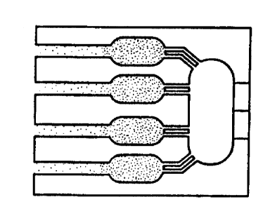
Figures l0A-C illustrate three versions of a consolidation circuit.
Figures 1 lA-E illustrate the combination of stopping means and air escape
vents to allow
fluid to bypass a particular fluid circuit section. The bypassed region can be
later perfused by a
2o downstream stopping means generating enough backpressure to overcome the
original stopping
means that prevented flow into the non-perfused region.
DETAILED DESCRIPTION OF TH . INVENTIQN
The invention is a method of using passive stopping means in microchannels to
control
the flow of fluids through the microchannels. A microchannel is defined herein
to be a channel
having a diameter of from 0.1 to 1000 microns. Advantage is taken of the
surface effects between
a fluid and the walls of the container holding the fluid. These surface
effects come into play at
the micro scale. The stopping means are designed to impede the flow of fluids
under certain
conditions thereby allowing control of the fluid. These stopping means act as
passive valves
3o because they regulate fluid flow but do not move.
An example of the effect of surface forces is capillarity. Capillarity, or
capillary action,
is demonstrated when water is drawn up into an open glass capillary tube
without any outside
SUBSTITUTE SHEET (RULE 26)
CA 02347182 2001-04-11
WO 00/22436 PCT/US99/23729
pressure being applied. This is caused by the surface tension forces between
the water and the
glass surface, which pulls water into the capillary tube. The narrower the
capillary tube the greater
the effect of the force that pulls the water into the tube. One physical
parameter that characterizes
the magnitude of the capillary force is the contact angle between the water
and the glass. For
contact angles less than 90°, the material, e.g., glass, is considered
to be hydrophilic and water is
drawn up into the tube. When the material has a contact angle greater than 90
° it is considered
to be hydrophobic. In the hydrophobic case extra pressure is required to push
water into an open
tube. The narrower the tube the greater the force that is required. However,
in both cases, once
water has been introduced into the tube the flow rates of the water are
dependent more on pressure
gradients and friction and less on whether the material is hydrophobic or
hydrophilic.
A stopping means is generated by altering the character of a microchannel in
such a way
as to generate a pressure barner. A pressure barrier is made by creating an
abrupt change in the
capillary force a fluid experiences while flowing through a mierochannel. An
abrupt change in
capillary force can be made by changing the diameter of the microchannel the
fluid is flowing
through, by changing the contact angle of the microchannel material, by
changing the surface
tension of the flowing fluid, or by a combination of these methods.
In a hydrophobic material a pressure barrier can be generated by decreasing
the diameter
of the flow channel. This restriction (a narrowing) should be sufficient to
cause fluid to flow in
alternate channels having a diameter greater than the restriction means. A
narrowing of a channel
can be effected by different means. For example, a channel of otherwise
constant diameter can
have a bump or ridge at one or more points that cause a narrowing just at
those points. Another
alternative is a channel of one diameter narrowing suddenly to a channel of a
smaller diameter,
i.e., a wide channel narrowing to a less wide channel. The magnitude of the
pressure barrier that
is generated is proportional to the narrowness of the restriction compared to
the narrowness of the
channel prior to the restriction. A short restriction will have minimal effect
on fluid flow once
flow is established through the restriction. It is preferred that the
restriction be I-1000 pm long,
more preferably 5-500 um long, and most preferably I O-300 pm long.
In a hydrophilic material a pressure barner can be generated by a channel
restriction,
similar to the method described for a hydrophobic material. However, in this
case the fluid will
3o not want to exit a restriction, due to the capillary forces that are
holding it there. The magnitude
of the pressure barrier that is generated is proportional to the narrowness of
the restriction
compared to the nanrowness of the channel after the restriction. A short
restriction will have
SUBSTITUTE SHEET (RULE 26)
CA 02347182 2001-04-11
WO 00/22436 PCT/US99/23729
minimal effect on fluid flow once flow is established through the restriction.
Also, in a hydrophilic material, a pressure barrier can be generated by
changing the contact
angle of the flow channel. Microfabrication techniques, for example, allow for
the precise
application of thin films of various materials that have a wide range of
contact angles. The
magnitude of the pressure barner that is generated is proportional to the
difference in the cosines
of the contact angles of the materials comprising the stopping means.
A stopping means can also be generated by changing the surface tension of the
fluid within
the microchannel. This, also, could be realized by utilizing microfabrication
techniques to deposit
thin f lms of various salts or surfactants that are absorbed into the fluid.
The magnitude of the
1o pressure barner that is generated is proportional to the difference in the
surface tensions of the
fluid on each side of the stopping means.
It is advantageous to use passive fluid dynamics to control the flow of fluid
in micro
channels or sets of micro channels. For example, if two daughter channels
branch off of a main
channel, a stopping means in one of the channels may encourage the fluid to
flow in the channel
with no stopping means. However, once the fluid has pushed past the stopping
means, the
stopping means, if designed properly, should have negligible effect on the
established flow within
the channels. In this case the stopping means acts as a passive valve.
The use of micro channels can be incorporated into a variety of techniques,
e.g., splitting
a sample into multiple chambers or samples or combining or mixing multiple
samples together.
2o Many variations of micro channel configurations can be designed for a
particular need. The
following examples illustrate some of the designs that are quite useful.
SUBSTITUTE SHEET (RULE 26)
CA 02347182 2001-04-11
WO 00/22436 PCT/US99/23729
Use of Passive Valves in Micrn ~'hannels tn Mix Sam l~ec
Figures 2A-J illustrate the use of stopping means in microchannels to regulate
the flow of
fluid through the channels. In Figure 2A, fluid in the main channel encounters
stopping means
'a', causing the flow to be diverted into channel 2. In Figure 2B, the fluid
in channel 2 encounters
stopping means 'b' which has a greater pressure barrier than stopping means
'a'. As a result, the
fluid flow is stopped by stopping means 'b' and the fluid is forced past
stopping means 'a' into
channel 1. Figure 2C illustrates the fluid in channel 1 at the timepoint at
which it reaches stopping
means 'b'. This causes the wetting of all surfaces on all sides of stopping
means 'b'. The
1 o meniscus which had been present at stopping means 'b' disappears thereby
allowing fluid to freely
pass stopping means 'b'. In Figure 2D, flow proceeds in both channels 1 and 2
without
obstruction. This example shown in Figures 2A-J shows a method by which two
fluids can be
mixed after insertion into a set of microchannels via a single microchannel.
The example shows
a first fluid inserted first into a main channel. A precisely measured amount
of this first fluid can
be inserted into the main channel. Following insertion of the first fluid, a
second fluid is inserted
into the main channel behind the first fluid. This second fluid forces the
first fluid along the main
channel until stopping means 'a' is reached. The first fluid is forced by this
stopping means into
channel 2. Once channel 2 is filled and the first fluid reaches stopping means
'b', flow through
channel 2 is stopped because stopping means 'b' has a greater pressure barrier
than stopping
2o means 'a'. The force of the fluid in the main channel then forces the
second fluid (all of the first
fluid in this example having entered channel 2) past stopping means 'a'. When
the second fluid
reaches the point of stopping means 'b' the pressure barrier of stopping means
'b' is overcome due
to the wetting of both sides of stopping means 'b' and the removal of the
meniscus which had
originally formed at this point. At this point fluid will flow through
channels 1 and 2 according
to their respective impedances, and the first fluid that was in channel 2 will
mix with the second
fluid which was in channel 1, this mixing occurnng in channel 1 subsequent to
stopping means
'b'.
Figure 2E illustrates the geometry and position of the stopped fluid if
stopping means "a"
were that of a hydrophobic restriction. Figure 2F illustrates the geometry and
position of the
3o stopped fluid if stopping means "b" were that of a hydrophobic restriction.
Figure 2G illustrates
the geometry and position of the stopped fluid if stopping means "a" were that
of a hydrophilic
restriction. Figure 2H illustrates the geometry and position of the stopped
fluid if stopping means
SUBSTITUTE SHEET (RULE 26)
CA 02347182 2001-04-11
WO 00/22436 PCT/US99/23729
"b" were that of a hydrophilic restriction. Figure 2I illustrates the geometry
and position of the
stopped fluid if stopping means "a" were that of a hydrophobic patch or a film
of salt. Figure 2J
illustrates the geometry and position of the stopped fluid if stopping means
"b" were that of a
hydrophobic patch of greater contact angle than that of "a", or a film of salt
that generates a
s greater surface tension in the fluid than that of "a".
The example of mixing fluids as illustrated by Figures 2A-J is a very simple
model. More
complex models in which more channels are involved could be utilized to mix
more than two
fluids together or to mix two fluids at one timepoint and other fluids at
later timepoints, e.g., by
having further branches similar to channel 2 farther downstream. The fluids
which are inserted
to into the main channel can be inserted by several means. The main channel
can encompass a single
port into which all fluids are inserted or it can encompass multiple ports
through which fluids can
be inserted. The volume of fluids inserted can be matched with the volumes of
channels to yield
precise filling of channels and proper mixing of the fluids.
1s
Filling of Multiple Channels or Chambers with a Sine;le Fluid
Another example of utilizing passive valves is in a network of parallel
daughter channels
that flow through a set of parallel wells or chambers. The goal in this case
is for a fluid or sample
to be evenly distributed across all channels, and for all of the wells or
chambers to fill
2o simultaneously, and for the fluid in the wells or chambers to stop in the
wells or chambers and not
to continue flowing into the well or chamber outlet channel until desired.
Once it is desired for
the fluid to continue flowing, it is desired that the fluid flow equally
further down the fluid circuit,
and equally into another set of chambers or wells, if present. This is
performed automatically due
to passive fluid dynamics. As fluid in the main channel flows toward the
parallel daughter
2s channels and wells or chambers, imperfections in the channel walls may
encourage increased flow
in one channel over another. The channel with increased flow will reach the
well or chamber and
fill up before its sister wells or chambers are filled. However, stopping
means located at strategic
points in the branching daughter channels will allow fluid to fill the
branching channels and catch
up and stop at each generation of stopping means before proceeding further
down the fluid circuit.
3o Each generation of stopping means will need to have a greater pressure
barrier than the previous
generation, in order to ensure the fluid does not pass one stopping means in
one branch without
first catching up to that generation of stopping means in ail branches. In
order to ensure each well
SUBSTITUTE SHEET (RULE 26)
CA 02347182 2001-04-11
WO 00!22436 PCT/US99/23729
11
or chamber is equally filled the wells or chambers are designed with stopping
means at their
outlets. Because it requires greater pressure for the fluid in the filled well
or chamber to go
through the stopping means, the increased pressure that is generated will push
the fluid in the
remaining channels to cause them to overcome any small wall imperfection and
catch up to the
fluid that is already in the well or chamber. Hence, the stopping means acts
as a passive valve an
allows for an even division of fluid from a single channel into several
daughter channels. It also
allows for a specific sample in a main channel to be evenly distributed across
a network of
channels. The relative structures of the stopping means will depend on the
materials, the fluid,
and the pressure that is required to push the fluid past any imperfections and
into all the channels,
1 o wells or chambers.
Figures 3A-G illustrate the effect of imperfections in microchannels and the
use of
stopping means to overcome problems that could have been caused by the
imperfections. It also
illustrates how a sample in a main channel can be evenly distributed across
multiple daughter
channels. In Figure 3A fluid in one branch encounters less friction and
travels further than fluid
in another branch, but is stopped at the first generation of stopping means.
Figure 3B illustrates
the distribution of fluid and sample as the fluid in one set of branches reach
the second generation
of stopping means. Figure 3C shows that the stopping means at the outlet of
the wells or
chambers allow all chambers to be filled, as the back pressure generated by
these stopping means
causes the fluid in all the branches to push past any previous stopping means
and fill the chambers
2o equally. Figure 3D shows that once all wells or chambers are filled, and
the desired processing
in the wells or chambers is completed, fluid can be pushed out of wells or
chambers, through the
outlet channels, and further down the fluid circuit until the next generation
of stopping means are
encountered. In Figures 3A-D the dark fluid is a sample and the lighter fluid
is the system fluid.
Ticks at the bottom of each figure represents the positions of the various
generations of stopping
means. Figure 3E illustrates the geometry and position of the stopped fluid if
the stopping means
were that of a hydrophobic restriction. Figure 3F illustrates the geometry and
position of the
stopped fluid if the stopping means were that of a hydrophilic restriction.
Figure 3G illustrates
the geometry and position of the stopped fluid if the stopping means were that
of a hydrophobic
patch or a film of salt.
3o It is also clear to one of skill in the art that the apparatus shown in
Figures 3A-G need not
be limited to 8 wells or chambers, rather many more wells or chambers could be
present.
Furthermore, there is no need for the wells or chambers to all be of the same
size. This makes the
SUBSTITUTE SHEET (RULE 26)
CA 02347182 2001-04-11
WO 00/22436 PCTNS99/23~29
12
division of a single sample injected at point 'a' into many separate wells or
chambers a very
simple matter. Many reaction wells or chambers can be filled without the need
for pipetting
individually into each well or chamber. Rather the sample is simply inserted
into the apparatus
at point 'a' and the microchannels and physical forces involved result in the
filling of all wells or
chambers.
IJse of an Air Duct in a Microfluirli~ ~'irrmit
Another application of a stopping means is that of an air escape duct. In a
hydrophobic
1 o material utilizing a narrow channel as a stopping means it takes a
considerable amount of pressure
to force fluid into an extremely small channel or duct (on the order of a few
microns in diameter).
Because of this water will easily flow by such a duct and continue down the
channel it is in and
not enter the duct. Air, on the other hand, will have no difficulty moving
through the duct if its
path in the fluid is restricted. This fact allows a method of releasing air
bubbles that might be
trapped within a fluid channel. A similar air escape duct can be fabricated in
hydrophilic materials
using a restriction and then a widening of the channel, or by utilizing a
hydrophobic or salt patch.
Figure 4A shows fluid traveling down two channels that join together. Figure
4B shows
the fluid in the lower channel reaching the intersection before the fluid in
the upper channel. In
such an event an air bubble will trap the fluid in the upper channel and
prevent the fluid in that
2o channel from traveling further. Figure 4C illustrates how this can be
overcome by the addition
of an air escape duct. In this case, fluid in the upper channel can continue
to flow as the air bubble
travels out of the channel into the air duct. In this illustration the air
duct is represented by a long
narrow channel, as might be indicative of a stopping means in a hydrophobic
material. Figure 4D
illustrates fluid in both channels combining into the single channel and
continuing to travel down
the fluid circuit. Figure 4E illustrates the geometry and position of the
stopped fluid if the stopping
means were that of a hydrophobic restriction, rather than a hydrophobic long
narrow channel.
Figure 4F illustrates the geometry and position of the stopped fluid if the
stopping means were that
of a hydrophilic restriction. Figure 4G illustrates the geometry and position
of the stopped fluid
if the stopping means were that of a hydrophobic patch or a film of salt.
Another application of an air escape duct is to allow air to escape a fluidic
circuit as fluid
fills the circuit. This is usually done by having air escape ducts at the
endpoint in a fluid circuit,
which would allow air to escape the enclosed system. This utilization of air
escape ducts are
SUBSTITUTE SHEET (RULE 26)
CA 02347182 2001-04-11
WO 00/22436 PCT/US99/Z3729
13
depicted in Figures SA-D, Figure 6, Figures 8A-C, and Figures l0A-C which are
described in
greater detail in the following Examples.
,T1
Consolidation of Fluid
Consolidation is the case where the contents of two or more channels or wells
are to be
combined into a fewer number of channels or wells. An example would be when 4
separate
nucleic acid sequencing reactions are performed and then it is desired to
combine the 4 reactions
into a single well to be run on a gel or other analytical device. Four
somewhat different
1o consolidation methods are set out in this example.
A) Two Fluid Narrow Channel Method
This method uses two fluids with a more viscous fluid being used to force a
less viscous
fluid through microchannels into a chamber or well to combine the less viscous
fluid from
15 multiple chambers or wells into a fewer number of chambers or wells. This
method is illustrated
by Figures SA-D.
The channel or wells to be joined are filled with a fluid. The outlet of the
wells or
channels contain stopping means used to contain the fluid at that point in the
fluid circuit. At
some point upstream there is a second fluid that is more viscous than the
first. There are narrow
2o channels that connect the stopping means of the channels or wells to the
point of joining. The first
fluid is stopped at the stopping means (Figure SA). As the second viscous
fluid advances down
a channel it will force the first fluid through the stopping means into the
narrow channel and into
the point of joining or consolidation chamber (Figure 5B). When the second
fluid reaches the
stopping means it does not stop because the fluid meniscus is gone. However,
the pressure
25 required to force the more viscous solution through the narrow channel is
instead used to push the
first fluid in a neighboring channel into the point of joining (Figure SC).
This process is repeated
until all wells or channels are emptied of the first fluid and the pumping is
stopped (Figure SD).
Figures 3E-G illustrate the possible geometries and positions of the stopped
fluid if the stopping
means at the outlet of the channels or wells were that of a hydrophobic
restriction, a hydrophilic
3o restriction, or a hydrophobic patch or salt film, respectively. If the
material were hydrophobic,
only a long narrow channel would be needed, rather than both a restriction and
then a long nan ow
channel. The utilization of air escape ducts at the consolidation chamber
would be similar to those
SUBSTITUTE SHEET (RULE 26)
CA 02347182 2001-04-11
WO 00/22436 PCT/US99/23729
14 '
depicted in Example 3 and Figures 4E-G.
Since the narrow connecting channels are very small there is a high chance of
them
becoming occluded by small particles. To reduce this risk redundant channels
may be made.
This is illustrated by Figure 6. This will help ensure the likelihood of an
open channel being
present to allow proper consolidation.
B) Joining Channel with Restriction and Air Escape Vent Method
The concept of having an air escape vent present to allow the release of what
normally
would be a trapped bubble is discussed above in Example 3. A variation is
shown here in a
to method of consolidation wherein stopping means are present (see Figures 7A-
D). Figure 7A
shows two fluids each entering a channel. Each channel has a stopping means at
the point where
the two channels on the left join to become a single channel. This allows the
fluid in both
channels to catch up to themselves at the point where the channels join
(Figure 7C). The presence
of an air vent in each of the two initial channels ensures that neither
channel will have an air lock
and both will advance to the joining region. Once one fluid breaks through its
stopping means it
will wet the other surface of the stopping means in the neighboring channel,
eliminating its
meniscus. This will allow both fluids to flow into the joining channel and mix
together (Figure
7D). Structure and position of fluid in the stopping means and air escape
ducts have been shown
in Figures 2E-J and 4E-G.
C) Air Displacement Method
Another method of consolidation requires the use of ports coming from a third
dimension,
e.g., from above or below. The ports possess stopping means at their
connection point to the fluid
channel so that, under normal operating pressures, fluid will not flow into
them. Fluid flows into
welts or channels and is stopped at a known location due to the use of
stopping means (Figure 8A,
stopping means exist at the right of each of the 4 initial wells between each
well and the exiting
microchannel). Air or another gas is pushed through the ports (appearing as
holes to the left of
the 4 initial wells in Figures 8A-C) into the fluid channels. The air will
displace the fluid
downstream past the stopping means (Figure 8B), and in this case, into the
consolidation well
(Figure 8C). Air escape ducts in the consolidation well allow displaced air to
exit the system, so
fluid can fill the consolidation well. A second fluid, rather than air, could
also be pushed through
the ports and used to displace the well volumes into the consolidation
chamber.
SUBSTITUTE SHEET (RULE 26)
CA 02347182 2001-04-11
WO 00/22436 PCT/US99/23'129
15 '
D) Physical Displacement Method
This method also requires the use of a third dimension. In this case a
portion, preferably
the top or bottom, of the fluid circuit is made to be flexible at the point
where physical
displacement is to occur. The top or bottom plate has an opening that can
allow a displacement
means to compress the flexible fluid circuit to push fluid further downstream.
This displacement
means can be a fluid such as water, a gas such as air, or a plunger of some
kind. This is illustrated
in Figures 9A-D. Figure 9A shows an empty circuit. Figure 9B shows the circuit
partially filled
with fluid. The bottom of the wells is made of a flexible material. In this
example, a displacement
means (water) is introduced below the last well filled with fluid. The water
compresses the
l0 bottom of the well (Figure 9C) forcing the fluid from the well into the
neighboring empty well
(Figure 9D). The displacement means can be introduced elsewhere and need not
be directly at the
last filled well.
mplP 5
Modified Two Fluid Narrow .hanr,Pi l~ethod~ nfifomnlidar;r,r,
The method described above in Example 4, Section A, and illustrated in Figures
SA-D has
been modified to yield improved results. Two modifications are illustrated in
Figures 108-C with
Figure lOA showing the original design for comparison. The design shown in
Figure 10B
incorporates stopping means just upstream of each of the four wells. These
stopping means
facilitate an even distribution of a sample into each of the channel branches
leading to the four
wells. Although not illustrated in Figure 5A or 10A, the 4 channels leading to
the wells could
have branched off from a single source or alternatively could have come from 4
different sources.
In practice the design of Figure 1 OB does not work very well. This is because
hydrophobic
or hydrophilic restrictions act as jet nozzles pushing the second, more
viscous fluid into the first
fluid and causing unwanted mixing. This results in consolidation that is less
than optimum and
a fair amount of the second solution is found in the large consolidation well
at the right in Figure
IOB. Although this is useful as a mixing method, it is not the desired result
in this case.
Figure IOC illustrates a modification of the consolidation design that
eliminates the
unwanted mixing seen with the design shown in Figure l OB. The entrance
channel is put on the
3o side of the well and the well is shaped somewhat in the form of a bowling
pin where one bulb or
section is significantly larger than the other section and the channel joining
the two is not
necessarily narrow and sharp. This allows the velocity of the second fluid to
slow down and
SUBSTITUTE SHEET (RULE 26)
CA 02347182 2001-04-11
WO 00/22436 PCT/US99/23729
16
stabilize in the small first section before it interacts with the bulk of the
first fluid in the large
second section. If the transition between the first and second sections is
smooth and gradual the
second fluid (if properly chosen) will remain intact with itself and there
will be a clear division
between the first and second fluids as the second fluid fills the well and
forces the first fluid
through the narrow channel into the consolidation well.
Temporarilv B as ing a Fluid it Wt Sertinn
Example 1 illustrated the use of stopping means to divert fluid from one path
to a
branching path of a microfluidic circuit. Example 3 illustrated the use of air
escape ducts to allow
what would normally be trapped air to escape a channel and allow fluid to flow
through the
channel, and eventually combine with the fluid in a joining channel. Utilizing
these techniques
a fluid circuit section can be temporarily bypassed using stopping means that
divert fluid into a
different path. A downstream stopping means can be used to overcome the
pressure barrier at the
original stopping means, and then an air escape duct can be used to allow
fluid to flow through
the bypassed region and rejoin the fluid circuit from which it had been cut
off.
Figures 11 A-E illustrate this technique. In Figure 11 A fluid flows down a
main channel
and encounters a stopping means "a" that diverts the flow into a side channel.
When the side
channel rejoins the main channel it is prevented from entering the bypassed
region of the main
channel because of a second stopping means "b" that diverts the fluid to flow
further down the
main channel. At some point downstream another stopping means with a greater
pressure barner
than the original stopping means "a" causes fluid to push past stopping means
"a". An air escape
duct located at the upstream side of stopping means "b" allows fluid to flow
through the main
channel. When it reaches stopping means "b" the meniscus disappears and the
pressure barrier
at stopping means "b" is eliminated. Fluid can then flow through both the main
channel and side
channel according to their respective impedances. It is important that the
pressure barrier at
stopping means "b" is greater than the pressure barrier at stopping means "a"
to ensure fluid does
not push past stopping means "b" before it pushes past stopping means "a".
Figure 11B illustrates
a similar situation, except where fluid in a main channel is prevented from
entering a side channel
due to stopping means at "a" and "b". Figure 11 C illustrates a chamber or
well in the fluid circuit
that may be bypassed initially, or perfused initially, depending on the
location of the stopping
means and air escape ducts. Figure 11D illustrates a chamber that is located
at the point of joining
SUBSTITUTE SHEET (RULE 26)
CA 02347182 2001-04-11
WO 00/22436 PCT/US99/23~29
17
of two channels, where one inlet to the chamber is a bypassed branch from the
main channel.
Figure 11 E illustrates a main channel that includes a chamber, and a series
of secondary channels
that contain chambers and that are bypassed, all of which contain stopping
means to prevent their
perfusion, and air escape ducts that allow their ultimate perfusion. The
stopping means at the
upstream positions of the secondary channels are designed such that their
pressure barriers can be
overcome in the sequence that is desired, in this illustration from the top to
the bottom, for the
fluid circuit to function properly. The air escape ducts can either
sequentially lead to the
secondary channels that are not yet perfused, or can Iead to the outside via
ducts traveling in a
third dimension.
The above examples demonstrate methods of diluting or mixing two fluids
traveling beside
one another in a single channel, methods of allowing branching channels to
divide flowing fluid,
methods of allowing air to escape out of a fluid circuit, methods of
consolidating channels or
samples, and methods of temporarily bypassing a fluid path, all using passive
fluid dynamics
based on pressure barners created by manipulating fluid capillary forces.
While the invention has been disclosed in this patent application by reference
to the details
of preferred embodiments of the invention, it is to be understood that the
disclosure is intended
in an illustrative rather than in a limiting sense, as it is contemplated that
modifications will
readily occur to those skilled in the art, within the spirit of the invention
and the scope of the
2o appended claims.
SUBSTITUTE SHEET (RULE 26)
CA 02347182 2001-04-11
WO 00/22436 PCTNS99/23729
18
U.S. Patent 4,946,795
U.S. Patent 5,119,116
U.S. Patent 5,498,392
U.S. Patent 5,587,128
U.S. Patent 5,627,041
U.S. Patent 5,726,026
R.C. Anderson et al., "Microfluidic biochemical analysis system," Int. Conf.
On Solid-State Sens
and Act, Transducers '97, p477-80 (1997).
S.N. Brahmasandra et al., "A microfabricated fluidic reaction and separation
system for integrated
DNA analysis," Micro Total Analysis Systems '98, D.J. Harrison and A Van den
Berg, eds., p267-
70, Kluwer Acad. Publ., Dordrecht ( 1998).
K. Hosokawa et al., "Hydrophobic microcapiliary vent for pneumatic
manipulation of liquid in
pTAS," Micro Total Analysis Systems '9$, D.J. Harrison and A Van den Berg,
eds., p307-10,
Kluwer Acad. Publ., Dordrecht (1998).
P.F. Man et al., "Microfabricated capillarity-driven stop valve and sample
injector," IEEE 11'h
Annual Int. MEMS Workshop, p45-50 ( 1998).
SUBSTITUTE SHEET (RULE 26)