Language selection

Search

Patent 2347190 Summary

Third-party information liability

Some of the information on this Web page has been provided by external sources. The Government of Canada is not responsible for the accuracy, reliability or currency of the information supplied by external sources. Users wishing to rely upon this information should consult directly with the source of the information. Content provided by external sources is not subject to official languages, privacy and accessibility requirements.

Claims and Abstract availability

Any discrepancies in the text and image of the Claims and Abstract are due to differing posting times. Text of the Claims and Abstract are posted:

  • At the time the application is open to public inspection;
  • At the time of issue of the patent (grant).
(12) Patent: (11) CA 2347190
(54) English Title: BI-FUNCTIONAL IN-LINE PHONATION VALVE
(54) French Title: VALVE DE PHONATION EN LIGNE BIFONCTIONNELLE
Status: Deemed expired
Bibliographic Data
(51) International Patent Classification (IPC):
  • A61M 16/04 (2006.01)
  • A61M 16/20 (2006.01)
  • F16K 15/14 (2006.01)
(72) Inventors :
  • ZOWTIAK, JOHN (United States of America)
  • O'MAHONY, JOHN (United States of America)
  • FRIGGER, DAVID (United States of America)
(73) Owners :
  • TYCO HEALTHCARE GROUP LP (United States of America)
(71) Applicants :
  • MALLINCKRODT INC. (United States of America)
(74) Agent: MOFFAT & CO.
(74) Associate agent:
(45) Issued: 2009-06-23
(86) PCT Filing Date: 1999-10-01
(87) Open to Public Inspection: 2000-04-20
Examination requested: 2004-09-10
Availability of licence: N/A
(25) Language of filing: English

Patent Cooperation Treaty (PCT): Yes
(86) PCT Filing Number: PCT/US1999/022768
(87) International Publication Number: WO2000/021599
(85) National Entry: 2001-04-11

(30) Application Priority Data:
Application No. Country/Territory Date
09/170,037 United States of America 1998-10-13

Abstracts

English Abstract


An in-line phonation valve system (10) including a valve body (12) having
first and second ends (14, 16) through
which gas passes into and out of the valve body (12). The first end (14) is
connectable to a breathing tube connected to a patient's
airway, for passage of gas between the breathing tube and the valve body (12).
The second end (16) of the valve body (12) is
connectable to a gas line. A diaphragm-valve assembly (28) is provided which
includes a one-way valve (30) having a phonation
position permitting gas to pass through said valve body (12) toward said
patient when said patient inhales. The one-way valve
(30) in the phonation position substantially prevents gas from passing through
the valve body (12) when the patient exhales. The
diaphragm-valve assembly (28) is movable out of the phonation position, so as
to permit substantially free flow of gas through
the valve body (12) both toward and away from the patient when the patient
respectively inhales and exhales. The diaphragm-valve
assembly (28) is movable from the phonation position without disconnecting the
first end (14) from the breathing tube and the second
end (16) from the gas line. Preferably, the diaphragm-valve assembly (28) is a
removable cartridge which is replaceable with a
free-flowing ring cartridge insert (42).


French Abstract

Un système de valve (10) de phonation en ligne comprend un corps de valve (12) ayant des première et seconde extrémités (14, 16) par lesquelles un gaz passe dans le corps de valve (12) et hors de celui-ci. La première extrémité (14) est connectable à un tube respiratoire relié à une voie aérienne du patient, permettant le passage du gaz entre le tube respiratoire et le corps de valve (12). La seconde extrémité (16) du corps de valve (12) est connectable à un conduit de gaz. Un ensemble diaphragme-valve (28) est prévu lequel comprend une valve unidirectionnelle (30) ayant une position de phonation permettant au gaz de passer à travers ledit corps de valve (12) vers le patient lorsque celui-ci inhale. La valve unidirectionnelle (30) dans la position de phonation empêche sensiblement le passage du gaz à travers le corps de valve (12) lorsque le patient exhale. L'ensemble diaphragme-valve (28) quitte sa position de phonation pour permettre l'écoulement sensiblement libre de gaz à travers le corps de valve (12) à la fois vers et à l'opposé du patient lorsque celui-ci respectivement inhale et exhale. L'ensemble diaphragme-valve (28) quitte sa position de phonation sans débranchement de la première extrémité (14) du tube respiratoire et de la seconde extrémité (16) du conduit de gaz. De préférence, l'ensemble diaphragme-valve (28) est une cartouche amovible pouvant être remplacée par un insert cartouche annulaire (42) à écoulement libre.

Claims

Note: Claims are shown in the official language in which they were submitted.


1. An in-line phonation valve system (10) comprising:
-a valve body (12) having first and second ends through which gas passes
into and out of the valve body, the first end (14) adapted for connection to a
breathing tube
connected to a patient's airway for passage of gas between said breathing tube
and said valve
body, the second end (16) adapted for connection to a gas line,
-a diaphragm-valve assembly (28, 28a, 28b) comprising a one-way valve (30)
having a phonation position permitting gas to pass through said valve body
toward said
patient when said patient inhales, said one-way valve in said phonation
position
substantially preventing gas from passing through said valve body when said
patient
exhales, said diaphragm-valve assembly having a diaphragm (24) and valve seat
(22)
moveable as a unit from said phonation position so as to permit substantially
free flow of
gas through said valve body both toward and away from said patient when said
patient
respectively inhales and exhales, wherein said diaphragm-valve assembly is
positioned in
said valve body so as to be moveable out of said phonation position without
disconnecting
said first end from said breathing tube and said second end from said gas
line, so as to
permit said substantially free flow of gas.

2. The phonation valve system of claim 1, further comprising a valve body ring

cartridge insert (42), wherein said diaphragm-valve assembly is completely
removable from
said valve body and replaceable with said ring cartridge insert, so as to
permit said
substantially free flow of gas.

3. The phonation valve system of claim 1 wherein said diaphragm-valve
assembly includes a pivot (36) connecting said valve assembly to said valve
body, for
rotating said valve assembly within said valve body from said phonation
position, to a free-
flow position wherein said valve assembly is positioned longitudinally within
said valve
body, so as to permit said substantially free flow of gas.

4. The phonation valve system of claim 3 wherein said valve assembly has a
peripheral edge (38) which seats within an inner wall detent (40) of said
valve body when
said valve assembly is in said phonation position.

5. The phonation valve system of claim 1 wherein said diaphragm-valve
assembly is positioned within a laterally slidable member (46) within said
valve body,
wherein said slidable member includes a two-way gas passageway (48) therein,
and wherein


said slidable member is slidable from said phonation position in which said
diaphragm-
valve assembly is positioned within said valve body, to a position wherein
said two-way
passageway is positioned within said valve body to permit said substantially
free flow of
gas.
6. An in-line phonation valve system (10) comprising:
-a valve body (12) having first and second ends through which gas passes
into and out of the valve body, the first end (14) adapted for connection to a
breathing tube
connected to a patient's airway for passage of gas between said breathing tube
and said valve
body, the second end (16) adapted for connection to a gas line,
-a diaphragm-valve assembly (28, 28a, 28b) comprising a one-way valve (30)
having a phonation position permitting gas to pass through said valve body
toward said
patient when said patient inhales, said one-way valve in said phonation
position
substantially preventing gas from passing through said valve body when said
patient
exhales, said diaphragm-valve assembly being moveable from said phonation
position so as
to permit substantially free flow of gas through said valve body both toward
and away from
said patient when said patient respectively inhales and exhales, wherein said
diaphragm-
valve assembly is positioned in said valve body so as to be moveable out of
said phonation
position without disconnecting said first end from said breathing tube and
said second end
from said gas line, so as to permit said substantially free flow of gas,
wherein said
diaphragm-valve assembly is positioned within a laterally slidable member (46)
within said
valve body, wherein said slidable member includes a two-way gas passageway
(48) therein,
and wherein said slidable member is slidable from said phonation position in
which said
diaphragm-valve assembly is positioned within said valve body, to a position
wherein said
two-way gas passageway is positioned within said valve body to permit said
substantially
free flow of gas.

6

Description

Note: Descriptions are shown in the official language in which they were submitted.


CA 02347190 2008-05-05

BI-FUNCTIONAL IN-LINE PHONATION VALVE
BACKGROUND OF THE INVENTION

FIELD OF THE IM'ENTION

The present invention relates to an in-line phonation valve for a breathing
tube such
as a tracheostomy tube.
DESCRIPTiON OF THE BACKGROUND
AR_T
Phonation valves permit speaking by a patient having a breathing tube inserted
into
the patient's airway, such as a tracheostomy tube inserted into a patient's
trachea.
Various valves for tracheostomy tubes are known in the art, including those
disclosed in U.S. Patent Nos. 3,137,299, 4,040,428, 4,325,366, 4,759,356,
4,971,054,
5,259,378 and 5,765,560. Also of interest are U.S. Patent Nos. 3,924,637,
3,990,439,
4,538,607 and 4,627,433, German patent document DE 8514859U, and UK patent
document GB 2164424A.
In-line phonation valves have one end connected to a breathing tube inserted
into a
patient's body. A second end of an in-line phonation valve is connected to a
gas line of a
ventilator circuit.
Prior in-line phonation valves are unidirectional (one-way) valves that allow
inspiration only. This results in expiration through the patient's voice box
allowing the
patient to speak.
Typically, phonation valves are used only temporarily for speaking, and the
ventilator circuits must be disconnected for removing the phonation valves.
Additionally,
in-line phonation valves must frequently be cleaned.
There remains a need in the art for improved in-line phonation valves.
SUMMARY OF THE INVENTION
In accordance with the present invention, an in-line phonation valve system
comprises a valve body having first and second ends through which gas passes
into and out
of the valve body. The first end is connectable to a breathing tube connected
to a patient's
airway, for passage of gas between the breathing tube and the valve body. The
second end
of the valve body is connectable to a gas line. A diaphragm-valve assembly is
provided
which comprises a one-way valve having a phonation position permitting gas to
pass
I


CA 02347190 2008-05-05

through said valve body toward said patient when said patient inhales. The one-
way valve
in the phonation position substantially prevents gas from passing through the
valve body
when the patient exhales. The diaphragm-valve assembly is movable from the
patient when
the patient respectively inhales and exhales. The diaphragm-valve ascembly is
movable
from the phonation position without disconnecting the first end from the
breathing tube and
the second end from the gas line.
BRIEF DESCRIPTION OF THE DRAWINGS
Fig. 1A is a perspective view of a phonation valve in accordance with one
embodiment of the present invention.
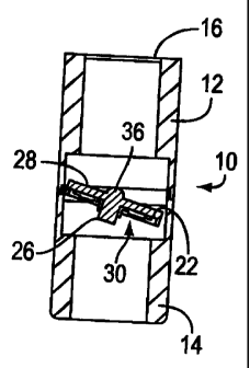
Fig. 1B is a partly schematic cross-sectional view of the valve of Fig. 1 in a
phonation position.
Fig. 1 C is a partly schematic 'cross-section of the valve of Fig. lA in an
intermediate
position.
Fig. 1D is a partly schematic cross-sectional detail of Fig. IC.
Fig. 2 is a schematic illustration, partially in cross-section, showing use of
a
phonation valve in accordance with the present invention.
Fig. 3A is a perspective view of a second embodiment of the present invention.
Fig. 3B is a partly schematic cross-section-of the valve of Fig. 3A, in a
phonation
position.
Fig. 3C is a partly schematic cross-section of the valve of Fig. 3A in a free-
flow
configuration.
Fig. 4A is a perspective view of a third embodiment of the present invention.
Fig. 4B is a partly schematic cross-section of the valve of Fig. 4A, in a
phonation
position.
Fig. 4C is a partly schematic cross-section of the valve of Fig. 4A in a free-
flow
configuration.
DETAILED DESCRIPTION OF THE PREFERRED EMBODIMENTS
Figs. lA-1D show an in-line phonation valve 10 in accordance with one
embodiment of the present invention. Phonation valve 10 includes a valve body
12 having
first and second ends 14 and 16 respectively through which gas, such as air,
oxygen or
anesthesia gas, passes into and out of valve 10.

2


CA 02347190 2008-05-05

The first end 14 of valve 10 is connectable to a breathing tube such as
tracheostomy
tube 18 shown in Fig. 2. Phonation valve 10 is an in-line phonation valve
wherein the
second end 16 is connectable to a source of gas such as oxygen (not shown) by
line 20 of,
for example, a ventilator circuit.
Referring back to Figs. lA-1D, a valve seat 22 is located within the valve
body 12
between the first and second ends 14 and 16 respectively. A thin, flexible
diaphragm 24 is
mounted circumferentially around a stem 26, and can be held on to stem 26 by
any suitable
means such as a mechanical fit. A diaphragm 24 can be formed of any suitable
thin, flexible
material, such as silicone rubber, and can have any suitable thickness, such
as about 0.005-
0.02 inch (0.013-0.05 cm).
In the embodiment shown in Figs. lA-1D, a diaphragm-valve assembly 28 is
shown.
Diaphragm-valve assembly 28 is comprised of a one-way valve 30 having a
phonation
position as shown in Fig. 1B which permits gas to pass through valve body 12
toward a
patient in the direction shown by arrow 32 when the patient inhales. One-way
valve 30,
when in the phonation position shown in Fig. 1B, substantially prevents gas
from passing
through valve body 12 when the patient exhales.
The diaphragm-valve assembly 28 is movable from the phonation position shown
in
Fig. 1B to the position shown in phantom lines in Fig. 1A, so as to permit
substantially free
flow of gas through valve body 10 both toward and away from the patient when
the patient
respectively inhales and exhales, in the directions of double-headed arrow 34.
In the embodiment shown in Figs. lA-1D, the diaphragm-valve assembly 28
includes a pivot 36 connecting the valve assembly 28 to valve body 12, for
rotating the
valve assembly 28 within valve body 12 from the phonation position shown in
Fig. 1B,
through the intermediate position shown in Fig. 1C to the free-flow position
shown in Fig.
1A, wherein the valve assembly 28 is positioned longitudinally within the
valve body 12 so
as to permit substantially free flow of gas.
As can be seen, the diaphragm-valve assembly is movable from the phonation
position, without the need to disconnect the first and second ends 14 and 16
of the valve
body from any tubes or lines.

3


CA 02347190 2008-05-05

As shown in Fig. 1D, valve assembly 28 has a peripheral edge 38 that seats
within an
inner wall detent 40 of the valve body 12 when the valve assembly is in the
phonation
position shown in Fig. 1B.
A second embodiment is shown in Figs. 3A-3C. According to this embodiment, a
valve assembly 28a shown in Fig. 3B is completely removable from the valve
body 12, and
replaceable with an open, valve body ring cartridge insert 42 shown in Fig.
3C, so as to
permit substantially free flow of gas through valve body 12. Both valve
assembly 28a and
ring insert 42 include finger tabs 44, shown in Fig. 3A, removal and insertion
into valve
body 12.
Figs. 4A-4C show a third embodiment in accordance with the present invention.
According to this embodiment, the diaphragm-valve assembly 28b, shown clearly
in Fig.
4B, is positioned within a laterally slidable member 46 within the valve body
12, as shown
in Fig. 4A. The slidable member 46 includes a two-way gas passageway 48
therein.
The slidable member 46 is slidable from the phonation position shown in Fig.
4B,
wherein the diaphragm-valve assembly 28b is positioned within valve body 12,
to a position
wherein the two-way gas passageway 48 is positioned within valve body 12 as
shown in Fig.
4C so as to permit substantially free flow of gas through valve body 12.
The slidable member 46 is provided with fmger tabs 44a for sliding the valve
between the position shown in Fig. 4B and 4C.
The present invention permits switching of an in-line phonation valve from a
unidirectional phonation position allowing a patient to speak, to a bi-
directional ventilation
position, without disconnecting the phonation valve from ventilator circuitry.

4

Representative Drawing
A single figure which represents the drawing illustrating the invention.
Administrative Status

For a clearer understanding of the status of the application/patent presented on this page, the site Disclaimer , as well as the definitions for Patent , Administrative Status , Maintenance Fee  and Payment History  should be consulted.

Administrative Status

Title Date
Forecasted Issue Date 2009-06-23
(86) PCT Filing Date 1999-10-01
(87) PCT Publication Date 2000-04-20
(85) National Entry 2001-04-11
Examination Requested 2004-09-10
(45) Issued 2009-06-23
Deemed Expired 2017-10-02

Abandonment History

There is no abandonment history.

Payment History

Fee Type Anniversary Year Due Date Amount Paid Paid Date
Registration of a document - section 124 $100.00 2001-04-11
Application Fee $300.00 2001-04-11
Maintenance Fee - Application - New Act 2 2001-10-01 $100.00 2001-09-25
Registration of a document - section 124 $100.00 2002-07-29
Maintenance Fee - Application - New Act 3 2002-10-01 $100.00 2002-09-23
Maintenance Fee - Application - New Act 4 2003-10-01 $100.00 2003-09-23
Request for Examination $800.00 2004-09-10
Maintenance Fee - Application - New Act 5 2004-10-01 $200.00 2004-09-21
Maintenance Fee - Application - New Act 6 2005-10-03 $200.00 2005-09-20
Maintenance Fee - Application - New Act 7 2006-10-02 $200.00 2006-09-19
Maintenance Fee - Application - New Act 8 2007-10-01 $200.00 2007-10-01
Maintenance Fee - Application - New Act 9 2008-10-01 $200.00 2008-09-23
Final Fee $300.00 2009-04-07
Maintenance Fee - Patent - New Act 10 2009-10-01 $250.00 2009-09-18
Maintenance Fee - Patent - New Act 11 2010-10-01 $250.00 2010-09-17
Registration of a document - section 124 $100.00 2011-08-30
Maintenance Fee - Patent - New Act 12 2011-10-03 $250.00 2011-09-19
Maintenance Fee - Patent - New Act 13 2012-10-01 $250.00 2012-09-17
Maintenance Fee - Patent - New Act 14 2013-10-01 $250.00 2013-09-17
Maintenance Fee - Patent - New Act 15 2014-10-01 $450.00 2014-09-25
Maintenance Fee - Patent - New Act 16 2015-10-01 $450.00 2015-09-24
Owners on Record

Note: Records showing the ownership history in alphabetical order.

Current Owners on Record
TYCO HEALTHCARE GROUP LP
Past Owners on Record
FRIGGER, DAVID
MALLINCKRODT INC.
MALLINCKRODT MEDICAL INC.
O'MAHONY, JOHN
ZOWTIAK, JOHN
Past Owners that do not appear in the "Owners on Record" listing will appear in other documentation within the application.
Documents

To view selected files, please enter reCAPTCHA code :


To view images, click a link in the Document Description column. To download the documents, select one or more checkboxes in the first column and then click the "Download Selected in PDF format (Zip Archive)" or the "Download Selected as Single PDF" button.

List of published and non-published patent-specific documents on the CPD .

If you have any difficulty accessing content, you can call the Client Service Centre at 1-866-997-1936 or send them an e-mail at CIPO Client Service Centre.


Document
Description 
Date
(yyyy-mm-dd) 
Number of pages   Size of Image (KB) 
Representative Drawing 2009-05-25 1 6
Description 2001-04-11 4 197
Cover Page 2009-05-25 1 48
Drawings 2001-04-11 4 79
Abstract 2001-04-11 1 62
Claims 2001-04-11 2 111
Representative Drawing 2001-10-02 1 5
Cover Page 2001-10-02 1 47
Drawings 2008-05-05 4 62
Claims 2008-05-05 2 98
Description 2008-05-05 4 173
Fees 2002-09-23 1 39
Prosecution-Amendment 2004-08-10 1 30
Fees 2008-09-23 1 58
Fees 2001-09-25 1 36
Prosecution-Amendment 2004-10-04 1 28
Prosecution-Amendment 2004-09-27 1 30
Correspondence 2001-06-18 1 25
Assignment 2001-04-11 7 285
PCT 2001-04-11 20 742
Assignment 2001-07-04 7 350
Assignment 2002-04-22 9 378
Correspondence 2002-06-19 1 21
Assignment 2002-07-29 3 94
Fees 2003-09-23 1 34
Fees 2004-09-21 1 33
Fees 2006-09-19 1 63
Fees 2005-09-20 1 34
Prosecution-Amendment 2007-11-07 2 37
Fees 2007-10-01 1 64
Prosecution-Amendment 2008-05-05 11 372
Correspondence 2009-04-07 1 42
Assignment 2011-08-30 60 2,063