Note: Descriptions are shown in the official language in which they were submitted.
CA 02347608 2001-09-26
ACTUATOR CAPABLE OF REVOLVING
BACKGROUND OF THE LNVENTION
The present invention relates to a revolution type actuator capable of using
its output as a
source for driving industrial machines, civil-use machines, and the like which
apply a revolutionary
motron.
Conventionally, a method has been employed for obtaining a revolutionary
motion as an
output by using an output transforming mechanism to thereby transform a
rotational motion of a
stepping motor, a DC (Direct Current) motor, or the like into a revolutionary
motion. On the other
hand, however, there has been known such a variable-gap type motor, a variable-
reluctance type
motor, or the like which revolve their movable element directly, as disclosed
in each gazette of the
Japanese Unexamined Patent Application Nos. HEI 8-205515 and HEI 1 1-275851.
Those motors
utilize an electromagnetic force generated in the same direction as the main
magnetic flux, thus
1 S featuring a low-speed high-torque rotation.
However, the above-mentioned method for transforming a rotation motion of a
stepping
motor, a DC motor and the like to a revolution motion by using an output
transforming mechanism
has suffered from such problems as friction, generated at the output
transforming mechanism portion,
deteriorating the efficiency and, the apparatus using such a method being
difficult to miniaturize. A
variable-gap type motor or a variable-reluctance type motor, on the other
hand, has a larger gap
length than the conventional type DC motor and the like and thus have stronger
leakage magnetic flux
and a larger gap variation, suffer from a problem of dit~iculty of high-speed
rotation.
CA 02347608 2001-09-26
SUMMARY OF THE INVENTION
In view of the above, it is an object of the invention to provide a revolution
type actuator
that can directly obtain a revolution motion without using the above-mentioned
output transforming
mechanism to thereby utilize that output as a source for driving industrial
machines, civil-use
machines and the like which apply a revolution motion and that can also
accommodate a high-speed
rotation based on its principle of having no variation in the magnetic gap
between its own movable
element and fixed element.
To this end, a revolving type actuator having a revolving movable element
revolving
according to the invention comprises a movable member capable of revolving
with respect to a fixed
member, a plurality of conducting paths arranged in a plane parallel to a
trajectory face of the
revolution motion for tlowing currents therein a plurality of currents in
mutually intersecting
directions, a power supply which flows currents having mutually different
phases in the plurality of
conducting paths, and a magnetic field generator which forms a magnetic field
in a direction
perpendicular to the conducting path, in which the movable member revolves by
an electromagnetic
force generated by an interaction between a current flowing in the conducting
paths and a magnetic
field formed by the magnetic field generator. The above-mentioned magnetic
field generator may be
comprised of a magnet and a stator magnetized by magnetic flux generated by
this magnet in such
a configuration that the above-mentioned movable member is disposed opposite
to the magnetic pole
of the magnet in a plane perpendicular to the magnetic flux interposed between
the magnet and the
stator and have a conductor attached thereto for forming the conducting path.
The revolution type actuator according to the invention, in which the movable
member
constrained from rotating by a rotation constraining mechanism is revolved
with a predetermined
2
CA 02347608 2001-09-26
revolution radius for driving machines, features that at least one conducting
path is formed which
flows a current on the above-mentioned revolution trajectory face or in a
plane parallel to this
revolution trajectory face to thereby form a magnetic field perpendicular to
the above-mentioned
conducting path so that an electromagnetic force generated by an interaction
between the above-
mentioned current and the electromagnetic force generated by the above-
mentioned magnetic field
may change the magnitude ofthe above-mentioned current for thus producing an
eccentric revolution
motion around a predetermined eccentric shaft, accordingly the revolution axis
and the magnetic flux
involved in the generation of the electromagnetic force are parallel with each
other to thereby
eliminate a variation in the gap between the movable member and the stator in
principle and so enable
designing the gap length sufficiently small within the most advantageous range
practical, thus
obtaining an excellent effect of being able to accommodate a high-speed
rotation, which has been
impossible with a prior art revolution type actuator.
BRIEF DESCRLPTION OF TH:E DRAWINGS
I 5 The above and other objects, advantages, and features of the invention
will be more apparent
from the following description taken in conjunction with the accompanying
drawings, in which:
FIG. 1 is a cross-sectional view for showing a revolution type actuator
according to a first
embodiment of the invention;
FIG. 2 is a series of perspective views for showing configuration examples of
conducting
paths and a magnetic field generator in the actuator of FIG. 1;
FIG. 3 is an illustration for showing an operating principle of the actuator
of FIG. 1;
FIG. 4 is a cross-sectional view for showing operations of a movable member of
the actuator
of FIG. I ;
FIG. 5 is an illustration for showing a path of magnetic flux in the actuator
of FIG. 1;
3
CA 02347608 2001-09-26
FIG. 6 is a cross-sectional view for showing a revolution type actuator
according to a second
embodiment of the invention;
FIG. 7 is a cross-sectional view for showing a revolution type actuator
according to a third
embodiment of the invention;
FIG. 8 is a cross-sectional view for showing a revolution type actuator
according to a fourth
embodiment of the invention;
FIG. 9 is a perspective view for showing a configuration example of a
permanent magnet
of the revolution type actuator of the fourth embodiment;
FIG. 10 is a cross-sectional view for showing a revolution type actuator
according to a fifth
embodiment of the invention;
FIG. 1 1 is a cross-sectional view for showing a revolution type actuator
according to a sixth
embodiment of the invention;
FIG. l2 is a cross-sectional view for showing a revolution type actuator
according to a
seventh embodiment of the invention;
F1G. 13(a) is a cross-sectional view for showing a revolution type actuator
according to an
eighth embodiment of the invention;
FIG. 13(b) is a cross-sectional view taken along line A-A of FIG. FIG. 13(a);
FIG. 14(a) is a cross-sectional view for showing a revolution type actuator
according to a
ninth embodiment of the invention, F1G. 14(b) is a cross-sectional view taken
along line A-A of FIG.
13(a);
FIG. 15 is perspective view for showing a configuration example of a
conducting path of
a revolution type actuator according to a tenth embodiment of the invention;
FIG. 16(a) is a cross-sectional view for showing a configuration example of a
conducting
path of a revolution type actuator of an eleventh embodiment ofthe invention,
FIG. 16(b) is a cross-
4
CA 02347608 2001-09-26
sectional view taken along line A-A of FIG. 16(a);
FIG. l7(a) is a cross-sectional view for showing a direction in which an
electromagnetic
force is generated when a current is conducted between 9g and 9c in a
configuration example of a
conducting path shown in FIG. 16(b), and FIG. 17(b) is a cross-sectional view
for showing a state
where a current is conducted between 9h and 9d,
FIGS. 18(a) and 18(b) are illustrations for showing configuration examples of
a revolution
type actuator and a conducting path according to a twelfth embodiment of the
invention,
FIGS. 19(a), l 9(b), 19(c), and 19(d) are illustrations for showing time-
sequential operations
of a conducting path;
FIG. 20 is a cross-sectional view for showing a configuration in a case where
the revolution
type actuator according to the eleventh embodiment of the invention is used as
a source for driving
a scroll pump;
FIG. 21 is an exploded perspective view for showing a scrolling portion of the
above-
mentioned embodiment;
FIG. 22 is an illustration for explaining operations of the above-mentioned
scrolling portion;
and
FIG. 23 is a cross-sectional view for showing a configuration in a case where
the revolution
type actuator according to the twelfth embodiment of the invention is used as
a source for driving a
scroll pump.
5
CA 02347608 2001-09-26
DETAILED DESCRIPTION OF THE PREFERRED EMBODIMENTS
Embodiments of the present invention will now be explained with reference to
the drawings.
(First Embodiment)
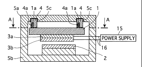
FIG. 1 shows a revolution type actuator according to a first embodiment of the
invention.
In FIG. 1, the revolution type actuator comprises a movable member 1 capable
of parallel movement
(revolution motion) with a predetermined revolution radius, a permanent magnet
2 for generating an
axial magnetic field, conducting paths 3a and 3b for generating an
electromagnetic force on the
above-mentioned movable member l, an eccentric shaft 4 for preventing of the
above-mentioned
movable member 1 from rotating and for revolving it with the predetermined
radius, and stators (iron
core) Sa and Sb entirely surrounded by a magnetic substance so as to prevent
magnetic flux occurring
from the above-mentioned permanent magnet 2 from leaking outside. The stators
Sa and Sb also
serve as an outer casing. Although the manner in which the revolution motion
of the movable
member 1 is utilized is not specifically illustrated, appropriately it may be
utilized in a scroll pump for
compressing a fluid as described in the following embodiment. In fact, the
revolution motion may
be output as is to the outside.
As for a mechanism for restricting the motion of the movable member 1 to a
revolution
trajectory and also constraining its rotation, at least two pins 1 a provided
as elevated to the movable
member I are fitted in a rotary manner to an eccentric hole 4a in the
eccentric shaft 4, which is in turn
held in a rotary manner by a bearing (not shown) at a hole Sc provided in the
stator Sa serving as a
fixing member. The conducting paths 3a and 3b are on a face parallel to the
trajectory face of the
revolution motion on which currents from an external power supply 15 flow via
a lead wire l G
through these paths 3a and 3b in intersecting directions with a phase
difference of 90° to each other.
The permanent magnet 2 and the stators Sa and Sb form in combination a
magnetic field
CA 02347608 2001-09-26
perpendicular to the conducting paths 3a and 3b (magnetic Held generator). In
this embodiment, the
conducting paths 3 a and 3b (conductors) are attached to the movable member l
, which revolves with
an electromagnetic force generated by an interaction between the currents
flowing through the
conducting paths 3a and 3b and the magnetic field produced by the permanent
magnet 2.
FIG. 2 shows a configuration example of the conducting paths 3a and 3b and the
permanent
magnet 2 for producing a magnetic field in various directions (indicated by an
arrow B in the figure)
in the revolution type actuator of this embodiment. The conducting paths 3a
and 3b are given on
respective paired circuit board in such a configuration that they flow
currents in a direction different
from each other (indicated by arrows) of printed wiring lines (intersecting
each other) at an angle of
90°. The movable member 1 can revolve at a predetermined revolution
radius, with the use of the
two eccentric axes 4, thus being constrained from rotating. The permanent
magnet 2 is magnetized
so as to generate a magnetic field in the direction of the revolution axis,
thus generating a
predetermined vertical magnetic field on the conducting path 3a and 3b.
When the above-mentioned conducting paths >a and 3b are supplied with AC
(Alternating
1 S Current) currents from the power supply I 5, a current flows perpendicular
to the axial magnetic Held
generated by the permanent magnet 2. Accordingly, as shown in FIG. 3, on the
conducting paths 3a
and 3b, an electromagnetic force F occurs (by the Fleming's left-hand rule) in
a direction
perpendicular to both a current I and a magnetic field (magnetic flux density)
B. The AC currents
supplied to the conducting paths 3a and 3b are given a phase difference of
90° therebetween, thus
providing a circle in motion of the direction of a sum of forces generated at
the conducting paths 3a
and 3b respectively. This et~ectively gives a force to the movable member 1 in
its predetermined
revolution direction so that it can revolve with the predetermined radius. As
a result, a load acting
on the trajectory constraining mechanism can be reduced. Also, no axial force
occurs, thus extremely
decreasing vibrations and the like.
7
CA 02347608 2001-09-26
FIG. 4 shows in a time series how the movable member 1 revolves. Also, FIG. 5
shows by
an arrow a closed magnetic path through which a magnetic flux due to the
permanent magnet 2 runs
in the actuator of this embodiment.
Although in this embodiment the conducting paths 3a and 3b are given on the
two circuit
boards stacked one on the other in such a configuration as to provide a phase
dit~erence of 90°
between the currents flowing through these paths, the possible configuration
is not limited to that
and, as described later, may be of such a mode as having only one conducting
path or even giving a
plurality of sheets of conducting paths. Also, the contiguration of the
conducting paths themselves
is not limited to this embodiment of providing circuit boards and, as
described later, may be of such
a mode as giving those conducting paths on a metal surface (face-shaped
conductor) or giving three
circuit boards stacked one on another so as to provide a phase difference of
120° between the current
flowing directions. Also, although this embodiment has employed a permanent
magnet as the
magnetic field generator, any other means may be used such as an electric
magnet or the like as far
as it has a sut~cient magnetomotive force.
(Second Embodiment)
FIG. 6 shows a revolution type actuator according to a second embodiment of
the invention.
In this embodiment, the movable member 1 is given as a movable iron core 10.
The movable iron
core 10 is appropriately made of a magnetic substance such as electromagnetic
soft iron,
electromagnetic steel or the like. Accordingly, the magnetic tlux starting
from the permanent magnet
2 passes through the conducting paths 3a and 3b, the movable iron core 10, and
the stator iron core
Sb to thereby suppress the leakage of the magnetic flux, thus improving the
magnetism efficiency.
Also, in this embodiment the stator Sa need not be made of a magnetic
substance any longer and can
be made of a resin, aluminum-based metal material or the like, thus reducing
the weight and the costs
8
CA 02347608 2001-09-26
of the relevant apparatus.
(Third Embodiment)
FIG. 7 shows a revolution type actuator according to a third embodiment of the
invention.
In this embodiment, opposite the movable iron core 10 of the above-mentioned
second embodiment,
the stator iron core Sb has a magnetization face 6 which is always magnetized
when it approaches
in a direction perpendicular to the revolution trajectory face. When the
movable iron core 10
revolves with the predetermined radius, the stator iron core Sb opposite the
movable iron core 10 is
always magnetized only in a direction perpendicular to the revolution
trajectory face, so that the
length of a gap between itself and the stator iron core Sb can be held roughly
constant, thus reducing
the leakage of the magnetic flux. Accordingly, the magnetism efficiency can be
improved. Also, this
effect can be maximized by sufficiently enlarging the outer diameter of the
movable iron core 10 to
always ensure magnetization throughout on the magnetization face 6 at the
upper end of the stator
iron core Sb during the revolution motion. Further, as compared to the above-
mentioned second
embodiment, an attracting force opposite in direction to the revolution motion
can be decreased
between the movable iron core 10 and the stator iron core Sb, thus improving
the energy efficiency.
(Fourth Embodiment)
FIG. 8 shows a revolution type actuator according to a fourth embodiment. FIG.
9 shows
a configuration example of the permanent magnet 2 in this actuator. This
embodiment is the same
as the above-mentioned second embodiment except in the method of magnetizing
the permanent
magnet 2. That is, in the permanent magnet 2 ofthis embodiment, the face
opposite the movable iron
core 10 is larger in area than the revolution trajectory region of the movable
iron core I 0 and also,
9
CA 02347608 2001-09-26
on the inner and outer peripheries on the same face are provided an N-pole and
an S-pole. The
magnetic flux starts at one of those poles on this face and passes through, as
indicated by an arrow
in the figure, the interior of the permanent magnet 2 and terminates at the
other pole on the same
face, from which it then enters the stator Sa, thus forming a magnetic
circuit. The permanent magnet
2 may be of such a configuration that the - and S-poles are opposite in layout
to FIG. 9. Also, the
configuration of the poles is not limited to the above-mentioned one. By using
such a magnetic
circuit, even without the stator iron core Sb, the magnetic flux can be
prevented from leaking to the
outside of a face opposite to the face having therein both poles of the magnet
2. By doing so, this
can thin the revolution type actuator.
(Fifth Embodiment)
F1G. 10 shows a revolution type actuator according to a fifth embodiment of
the invention.
This embodiment is the same as the above-mentioned second embodiment except
that the pole face
disposed opposite to the movable iron core 10 ofthe permanent magnet 2 is
larger in area than the
largest revolving region of the conductor paths 3. Further, the permanent
magnet 2 on the stator iron
core Sb has stator iron cores Sc and Sd thereon stacked on its surface which
are made of a magnetic
substance such as electromagnetic soft iron. The first layer in the stack
consists of the stator iron
core Sc having the same cross sectional shape as the permanent magnet 2 and
the second layer
consists of the stator iron core Sd having a smaller area than the above-
mentioned pole face and a
larger upper face area than the largest revolving region of the conductor path
3a or 3b, whichever
larger. Accordingly, the magnetic flux starting from the permanent magnet 2 is
concentrated as it
passes through the stator iron cores Sc and Sd in this order, to largely
enhance its density along the
conducting path 3, thus improving torque. Although in FIG. 10 the magnetic
substance is arranged
in the pole face in such a step-like shape as consisting of the stator iron
cores Sc and _Sd, the shape
CA 02347608 2001-09-26
is not limited to this embodiment. For example, those iron cores Sc and Sd may
be integrated so that
the upper face may be smaller in area than the pole face but larger than the
largest revolving region
of the conducting path 3a or 3b and the lower face may be of a frusto-conical
shape with the same
cross sectional area as that of the pole face, thus having the larger lower
face and the smaller upper
face with a tapered slope of the magnetic substance employed. Further, the
upper and lower faces
of the above-mentioned magnetic substance need not be the same or similar in
shape and may be of
any shape as far as it contributes to the solving of the above-mentioned
problems.
(Sixth and Seventh Embodiments)
FIG. 1 I shows a revolution type actuator according to a sixth embodiment of
the invention.
FIG. 12 shows a revolution type actuator according to a seventh embodiment of
the invention. In
FIGS. 1 1 and 12, these inventions are the same as the above-mentioned first
and second embodiments
respectively except that the conducting paths 3a and 3b are fixed and the
permanent magnet 2 is
movable. In F(G. 1 1, the entire movable member is made of the permanent
magnet 2, which
revolves. In FIG. 12, the movable member is given as the movable iron core 10
made of a magnetic
substance such as electro-magnetic soft iron and the like, to which the
permanent magnet 2 is
attached in configuration. In both FIGS. 1 1 and 12, by attaching the
conducting paths 3a and 3b to
the stator iron core Sb, these paths 3a and 3b themselves do not revolve to
thus simplify the
connection for supplying power from the power supply to them and also avoid a
problem of fatigue
and the like of the wiring caused by revolving, thus prolonging the service
life of the power supply
wiring lines.
(Eighth Embodiment)
FIGS. 13(a) and 13(b) indicate a revolution type actuator according to an
eighth
CA 02347608 2001-09-26
embodiment of the invention. This embodiment is the same as the above-
mentioned first embodiment
except that between the movable member 1 and the stator iron core Sb is
interposed a plurality of
compression springs 7 that can be compressed in the revolving plane of the
movable member 1 and
that has such a spring coefficient as to enable mutual resonance at a
predetermined vibration
frequency. That is, this embodiment uses the resonance of the springs to
thereby effectively utilize
the output energy of the revolution type actuator.
(Ninth Embodiment)
FIGS. 14(a) and 14(b) show a revolution type actuator according to a ninth
embodiment of
the invention. This embodiment is the same as the above-mentioned eighth
embodiment except that
a bearing 8 is interposed between the movable member 1 and the compression
springs 7 in
configuration. That is, by the eighth embodiment of directly attaching the
compression springs 7 to
the movable member l, a lateral force is applied to the compression springs 7
accelerating their
deterioration due to fatigue and the like, to guard against which this
embodiment transmits a force
to the movable member 1 via the bearing 8 at the tip of each of the
compression springs 7 as shown
in FIGS. 14A and 14B in configuration to thereby suppress their deterioration
due to fatigue and the
like, thus prolonging the service life of the revolution type actuator. Also,
although the above-
mentioned first through eighth embodiments have employed the circular shaped
movable member 1
or movable iron core 10, stators Sa and Sb, conducting paths 3a and 3b and the
like, the shape may
be a rectangle for the movable member 1, the stators Sa and 5b and the like.
Such a shape can also
enable a revolution motion of the movable member.
(Tenth Embodiment)
FIG. 15 shows a different configuration of the conducting paths 3 in an
actuator of the
12
CA 02347608 2001-09-26
invention. In this embodiment, the conducting paths 3a and 3b are made of
copper foil, with the
driving principle being the same as that of the first embodiment. In contrast
to the first embodiment,
however, the conducting paths 3a and 3b are sheet shaped to thereby flow the
current I throughout
on the face of the copper foil and the conducting portion can be enlarged in
cross-sectional area to
thereby reduce an energy loss due to the generation of the Joule's heat, thus
improving the energy
efficiency as a whole. Although this embodiment has formed the conducting
paths 3a and 3b of
copper foil, any other appropriate metal may be used instead. For example,
gold (Au), silver (Ag),
iron (Fe), aluminum (Al), or any other substance having the metal properties
may be used as far as
it contributes to the solving of the above-mentioned problems.
(Eleventh Embodiment)
FIGS. 16(a) and 16(b) indicate another different configuration example of the
conducting
paths in a revolution type actuator of the invention. In this embodiment, one
sheet of a copper sheet
3c (face-shaped conductor) is used in configuration as the face-shaped
metallic substance which the
above-mentioned conducting paths 3 are made of, through which currents flow so
that lead wires 9a
through 9h (electrodes) may run in a radial manner from the copper sheet 3 c
as shown in FIG. 16(b).
Also, magnetic flux M occurring from the permanent magnet 2 penetrates the
copper sheet
perpendicularly, thus forming a magnetic circuit. As for the direction in
which an electromagnetic
force is generated in this configuration of the conducting paths, FIG. 17(a)
shows a case where a
current is conducted between 9g and 9c and FIG. 17(b), a case where it is
conducted between 9h and
9d. If the copper sheet 3c is biased leftward as shown in FIG. 17(a), the lead
wires 9c and 9g are
placed under application of GND level (0 V) and a positive voltage (+V)
respectively to thereby flow
the current in an arrow direction, thus generating the force F toward the
viewer of the figure. If then
the copper sheet 3c comes near a position indicated in FIG. 17(b), the lead
wires 9d and 9h are
13
CA 02347608 2001-09-26
placed under application of GND (0 V) and a positive voltage (+V)
respectively, thus generating the
force F obliquely rightward toward the viewer of the figure. By thus changing
the lead wire to which
the voltage is applied, the force can be generated so as to revolve the
movable member l .
(Twelfth Embodiment)
FIGS. I 8(a) and 18(b) show a configuration of a revolving type actuator
according to a
twelfth embodiment of the invention and its conducting paths. FIGS. 19(a),
19(b), 19(c), and 19(d)
show time series-wise operations of the conducting paths. In this embodiment,
the conducting paths
3a, 3b, and 3c attached to the movable member I are stacked one on another
with insulation
maintained therebetween in such a configuration as comprised of a plurality of
sheets of face-shaped
conductors provided with the lead wires 9 (electrodes) for flowing currents in
different directions.
By changing the current flowing electrode sequentially, a current flowing
through each of the
conducting paths can be controlled, so that the directional electromagnetic
force F generated by the
interaction between this current 1 and the magnetic field B of the magnet 2
may provide a circular
motion time-wise.
(Thirteenth Embodiment)
FIG. 20 shows an embodiment in which a revolution type actuator of the
invention is used
as a source for driving a scroll pump. FIG. 21 shows a scrolling portion of
this embodiment. FIG.
22 shows pumping operations by the scrolling portion. As shown in those
figures, the movable
element is given as a movable scroll 1 1 and the fixed member is given as a
fixed scroll 12 in such a
configuration that the movable scroll l 1 is held on the fixed scroll 12 in a
revolution manner via the
eccentric shaft 4. Spiral blades 1 1 s provided to the movable scroll 1 1 and
spiral blades 12s provided
to the fixed scroll 12 are combined with each other to thereby form the scroll
pump By revolving
14
CA 02347608 2001-09-26
the movable scroll 1 1 around the eccentric shaft 4 with the predetermined
radius, an enclosed space
formed by the spiral blades of those two scrolls can be shifted from the
outside toward the center
side, thus consecutively reducing the volume of that enclosed space. On the
fixed scroll 12 a spiral
groove 12a has an inlet 12d formed in the outer periphery and an outlet 12e in
the center. In a hole
12c is held the eccentric shaft 4 in a rotary manner.
Thus, when the actuator of the invention is used as a source for driving a
scroll pump, the
movable scroll 1 1 can be directly driven in configuration as the movable
member of the actuator.
Accordingly, an extra transmission mechanism or motor as a driving source need
not be mounted
below the scroll pump, thus thinning the pump as a whole. The revolving
movable scroll 1 1 may be
entirely or partially made of a rare earth-based or ferrite-based permanent
magnet or a plastic magnet
having a magnetomotive force or such a magnetic substance as an
electromagnetic steel sheet or soft
iron.
(Fourteenth Embodiment)
F1G. 23 shows an embodiment in which two revolution type actuators of the
invention are
used vertically as a source for driving a scroll pump. Such a configuration
makes it possible to drive
the movable scrolls 1 la and I lb at the same time. Further, by delaying in
operation the movable
scroll 1 I b half a period from the movable scroll I 1 a, a center-to-center
relative distance between
them can always be double the revolving radius of the movable scroll. This
conversely means that
air can be compressed only by revolving the movable scrolls 1 1 a and 1 1 b
with a revolving radius
which is half that of the movable scroll conventionally necessary for
compressing the air. Also, the
vibrations of the movable scrolls 1 1 a and 1 1 b caused by a shift in the
center of gravity offset each
other. Accordingly, the vibration and noise can be reduced. In this
embodiment, the movable scrolls
CA 02347608 2001-09-26
1 la and I Ib are provided with the spiral blades 13s and 14s which are
combined with each other.
The stator Sa has the air outlet Se, in communication with which is provided
an air outlet pipe Sf
penetrating the movable scroll I 1 a etc. The inlet etc. are omitted in
illustration.
The revolution type actuator of the invention is not limited to the above-
mentioned
embodiments and various modifications may be made therein as far as they do
not depart from the
scope or spirit of the invention.
16