Note: Descriptions are shown in the official language in which they were submitted.
CA 02347956 2001-04-20
METHOD FOR OBTAINING AMMONIA FROM WASTE WATER
CONTAINING NH3 AND ACID GASES
Description
The invention relates 'Co a process for the recovery of
ammonia from waste water containing' NH3, at least one
acid gas (COZ and/or HZS) and inert gases, which is
firstly passed through a pretreatment column and then
applied, at least in part, to a total stripping column,
in which process a top product from the total stripping
column which comprises NH3 and acid gas is fed to a
condenser, in which the top product is scrubbed with
circulated and cooled condensate, an aqueous NH3-
containing condensate coming from the condenser is fed
to an NH3 stripping column, whose top product is
brought into direct contact with circulating aqueous
NH3-containing condensate in a wash.column, NH3 is
obtained from the top product from the wash column, and
some.of the bottom product from the wash column is fed
back into the NH3 stripping column. The waste water,
which always cvznprises at least onE of the ac~.d gases
COZ and/or HzS, may also comprise, for example, HCN.
~1 process of this type is disclosed in EP-B-0 212 690.
The pretreatment column here zs des:Lgned as a simple
CA 02347956 2001-04-20
- 2 -
stripping column, and consequently the treated waste
water still contains a considerable part of the
impurities that are difficult to remove. This results
in ammonia water fina~~y obtained :Likewise having a
relatively high content of impurities.
The invention has the object of modifying the known
process in such a way that the burden on the wash
column upstream of the NH3 recovery is reduced, and
clean, aqueous NH3 can be produced. This is achieved
according to the invention in the ~>rocess mentioned at
the outset in that the pretreatment. column is provided
with heating of the bottom region, and the temperature
in the bottom region is from X30 to 200°C, in that a
sub-stream of the waste water is introduced into the
upper region of the pretreatment column and a second
sub~strearn of the waste water is passed into the pre-
treatment column below 'the first sub-stream, in that at
least 80g and preferably at least Si5a of the NH3
present in the top product from the: total stripping
column is condensed in the condensE;r, and in that a
waste-water stream is taken off from the total
stripping column, at least part of the waste-water
stream is cooled to temperatures of from 10 to 60°C,
and the cooled waste-water stream is passed into the
top region of the pretreatment column.
lnext gases and acid gases (COZ and Hz5) are removed
very effectively in the pretreatment column, which
reduces the burden on the downstream columns. This
results, inter alia, in it being possible to condense
all of the top product from the total stripping column.
It is also possible to adjust the pressure in the wash
column while nevertheless obtaining clean ammonia
water,
The pressure in the pretreatment column is usually in
the range from l to 20 bar and is preferably at least
2 bar. The second sub-stream o~ the waste water, which
CA 02347956 2005-05-17
3
is passed into the pretreatment column below the feed
point of the first sub-stream, is preferably preheated
to temperatures of at Least 50°C and preferably at
least e0°C by indirect heat exchange with the waste
water coming from the bottom of the pretreatment
column.
It is advantageous to pass from 1 to 90ro of the waste
water taken off from the bottom of the pretreatment
column into the condenser while bypassing the total
stripping column. ~n this way, the load in the total
Stripping column can be regulated and ita heating
demand optimized.
More particularly, the present invention provides a process for the recovery
of NH3
from a waste water containing NH3, at least one acid gas selected from the
group
consisting of G02 and H2S, and an inert gas, which comprises the steps of:
a) dividing the waste water containing NH3, at least one acid gas selected
from the group consisting of C02 and H2S, and an inert gas into a first waste
water sub-stream and a second waste water sub-stream;
b) providing a pretreatment column with a heating means at the bottom to heat
the bottom to a temperature of 130 to 200°C, introducing the first
waste water sub-
stream into an upper region of the pretreatment column, and the second waste
water sub-stream into the pretreatment column at a location below the upper
region of the pretreatment column where the first waste water sub-stream is
introduced, to pretreat both the first and the second waste water sub-streams
to
remove the at least one acid gas from the waste water thereby providing a
waste
water stream at the bottom of said pretreatment column having undergone
removal of said at least one acid gas;
CA 02347956 2005-03-07
3a
c) cooling the waste water stream at the bottom of said pretreatment column
and channeling in part the waste water stream from the bottom of said
pretreatment column to a total stripping column to obtain a top product
comprising
NH3 and at least one acid gas, and a bottom product comprising a waste-water
stream, cooling the top product, and condensing at least 80% of the NH3
present
in the top product in a condenser in which the top product is scrubbed with
circulated and cooled condensate to obtain a waste gas comprising the inert
gas
and an aqueous NHg -containing condensate while channeling 1 to 40% of the
waste water having undergone removal of the at least one acid gas according to
step (b) directly from the bottom of said pretreatment column to the condenser
thereby avoiding the total stripping column to obtain additional waste gas
comprising the inert gas and additional aqueous NHg -containing condensate;
d) cooling the waste-water stream obtained as a bottom product from the total
stripping column according to step (c) to a temperature of 10 to 60°C
and passing
the cooled waste-water stream to the top region of the pretreatment column
according to step (b);
e) splitting the NHg -containing condensate obtained from the condenser
during step (c) into two portions, recirculating a first portion of the NH3 -
containing
condensate back to the condenser in step (c) to condense additional quantities
of
NH3 present in the top product, and from a second portion of the NH3 -
containing
condensate stripping NH3 in an NHg -stripping column to obtain NHg vapor at
the
top and a waste stream at the bottom; and
f) washing the NH3 vapor with circulating NHg -containing condensate in a
wash column and recovering NH3 as a top product from the wash column, said
NH3 free of said acid gas and said inert gas, while obtaining a bottom product
from the wash column, said bottom product recirculated to the NH3 -stripping
column in step (e).
CA 02347956 2005-05-17
3b
The invention also concerns a process for the recovery of NH3 from a waste
water
containing NH3, at least one acid gas selected from the group consisting of
C02
and H2S, and an inert gas, which comprises the steps of:
a) dividing the waste water containing NH3, at least one acid gas selected
from the group consisting of C02 and H2S, and an inert gas into a first waste
water sub-stream and a second waste water sub-stream;
b) providing a pretreatment column with a heating means at the bottom to heat
the bottom to a temperature of 130 to 200°C, introducing the first
waste water sub-
stream into an upper region of the pretreatment column, and the second waste
water sub-stream into the pretreatment column at a location below the upper
region of the pretreatment column where the first waste water sub-stream is
introduced, to pretreat both the first and the second waste water sub-streams
to
remove the at least one acid gas from the waste water thereby providing a
waste
water stream at the bottom of said pretreatment column having undergone
removal of said at least one acid gas;
c) cooling the waste water stream at the bottom of said pretreatment column
and channeling in part the waste water stream from the bottom of said
pretreatment column to a total stripping column to obtain a top product
comprising
NH3 and at least one acid gas, and a bottom product comprising a waste-water
stream, cooling the top product, and condensing at least 80% of the NH3
present
in the top product in a condenser in which the top product is scrubbed with
circulated and cooled condensate to obtain a waste gas comprising the inert
gas
and an aqueous NH3 -containing condensate;
d) cooling the waste-water stream obtained as a bottom product from the total
stripping column according to step (c) to a temperature of 10 to fi0°C
and passing
the cooled waste-water stream to the top region of the pretreatment column
according to step (b);
CA 02347956 2005-03-07
3c
e) splitting the NHg -containing condensate obtained from the condenser
during step (c) into two portions, recirculating a first portion of the NH3 -
containing
condensate back to the condenser in step (c) to condense additional quantities
of
NHg present in the top product, and from a second portion of the NHg -
containing
condensate stripping NH3 in an NH3 -stripping column to obtain NH3 vapor at
the
top and a waste stream at the bottom; and
f) washing the NH3 vapor with circulating NH3 -containing condensate in a
wash column and recovering NH3 as a top product from the wash column, said
NHg free of said acid gas and said inert gas, while obtaining a bottom product
from the wash column, said bottom product recirculated to the NHg -stripping
column in step (e).
Possible embodiments of the process are explained with the aid of the drawing,
in
which:
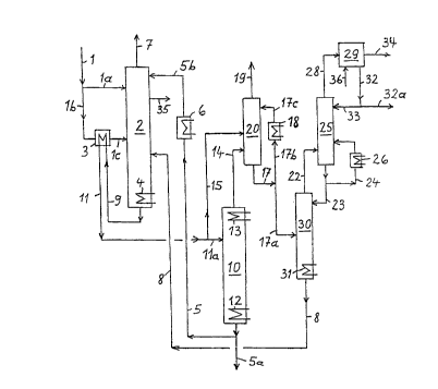
Figure 1 is a flow chart of the process.
The waste water to be treated is supplied in line (1).
Zt comes, for example, from a refinery or a plant for
coal gasi~ication, The waste water comprises NH3 as
va~uab~e substance and in addition numerous further
components, in particular one or more acid gases, such
as COZ and/or HzS, also inert gases and possibly HCN and
also residues of hydrocarbons or solvents. A first sub-
stream of the waste water is introduced through line
(la) into the upper region of a pretreatment column
(2). The remaining waste water is fed through line (1b)
and, before entry into column (2) through line (lc),
for example in its central region, is warmed to at
least SO°C and preferably at least 80°C in the indirect
heat exchanger (3). The pretreatment column (2) and the
other columns contain trays known per se or alter-
natively packing elements. The bottom region of column
(2) is provided with heating (4), enabling temperatures
of from 130 to 200°C to be achieved therein.
CA 02347956 2005-03-07
3d
Some of the waste water obtained in a total stripping
column (10) is fed through lines (5) and (5b) to the
CA 02347956 2001-04-20
- 4 -
top of column (2) after the waste water has been passed
through a condenser (6) and adjusted to temperatures in
the range from 10 to 60°C. A further waste-water stream
comes from an NH3 stripping column (30) and is fed
through line (8) to the lower part of column (2).
Stripped gases and vapors leave co:Lumn (2) in line (7).
If necessary, a water-containing l:Lquid stream
comprising hydrocarbons and/or solvents is taken off
through line (35) and fed to work~up, which is not
Shourn .
The waste water obtained at the botaom of column (2) is
'taken off in line (9), fed through heat exchanger (3)
for cooling and then applied to the: total stripping
column (10) in lines (11) and (11a). In column (10), it
is ensured that all the free NH3 and remaining acid
gases are removed from the waste water. To this end,
column (10) is fitted with bottom heating (12), by
means of which the bottom liquid is brought to tempera~-
tures of from 100 to 1$0°C. Column (10) furthermore
contains top cooling (13). It may be advantageous from
a Control. engineering point of view 'to branch off a
sub-stream of from 7, to 405 of the waste water coming
from the heat exchanger (3) and supplied in line (11)
and to feed it through line (15) into the condenser
(20). A sub-stream of the waste water taken off from
column (10) is removed through line (5a) arid can be
fed, :for example, to biological waste-water treatment.
The NH3-rich top product from column ( ~,0 ) is fed
through line (14) into a condenser (20), which ~.s
likewise fitted with trays or packing elements.
Condensate coming from condenser (la3) and part~.ally
circulated through lines (1?) and (:L7b) is intz~oduced
into the upper region of condenser (20) through line
(17c). The gas mixture taken off from condenser (20) in
line (19) comprises maznly inert gases.
CA 02347956 2001-04-20
The condensate in line (17) is spl~_t over lines (17a)
and (17b). Zine (17a) leads to the NH3 stripping column
(30), which is likewise fitted with heating (31). The
bottom liquid from column (30) is f:ed back to the pre-
treatment column (2) through line (8) ~.n the manner
already explained. The top product is introduced
through line (22) znto the wash col.urnn (25), whose
design and mode of operation is described in detail in
EP-B-0 212 690. Some of the liquid flowing out in
column (25) is fed back into column (30) through line
(23), and the remaining liquid is,fed back into the
lower region of column (25) by means of the circuit
through line (24) and condenser (26). Column (25) is
preferably designed as a Wetted-wall column divided
into several sections, the pressure being in the range
from 1 to 20 bar and the temperatures being from 20 tv
l00°C,
A gas mixture consisting principally of NH3 is taken
off from the top of column (25) in line (2~0) and fed to
ammonia liquefaction (29), from which .liquid ammonia is
taken off in line (34) and/or ammonia water is taken
off in line (32). Sorne of the ammonia water is fed back
to the top of column (25) through line (33), and the
remainder is available in line (32a) as a further
valuable product. It is possible to generate either
aqueous or liquid ammonia or both products. If
necessary, water is supplied in line (36).
Example 1
waste water from a petroleum refinery which has been
pretreated in a 3-phase separator is passed through
line (1) to the work-up shown in the drawing, where
aqueous ammonia is produced. Line (34) is superfluous.
After pretreatment in the 3-phase separator, the waste
water still contains small amounts of hydrocarbons,
which are taken off via line (35).
CA 02347956 2001-04-20
- 6 -
The following table shows the amounts (in kg/h) of the
principal components HZO, NH3, HZS a3nd Co2 and the
pressure and temperature for the m<~st important lines;
some of the data are calculated. The waste water in
line (1) also contains_inert gases (for example Hz),
which are taken off via line (7). :Cnert-gas residues
leave the work-up through line (19).
Table
Line H20 NH3 . H2S C02 ~ ( p (bar)
C)
1 44$70 851 900 1.000 35 13
la 4711 89 95 :105 35 13
1c 40159 762 805 X395 139 12.5
5b 1820 0.1 0 ~0 35 3.5
5a 45320 2 0.2 0 144 4
7 8 0.1 99.8 1000 45 Z0.7
4401 1800 540 37 75 3.5
9 51083 2651 540 37 165 11
. 11a 4400 2512 5~.2 35 86 11
14 1260 2510 512 35 110 4
15 26$3 139 28 2 86 11
17a 3943 2049 540 37 56 4
1.7c 92849 62378 12716 871 47 4
22 21 1130 6 0'.2 45 3.4
23 479 281 f 0.2 44 3.3
24a 5576 3272 70 2.3 40 3,3
2B 21 1009 0 0 45 3
32a 2548 849 0 0 45 3
33 479 160 0 0 45 3
35 3006 0 0 0 30
Various lines contain traces of li2S and/or COZ in the
,. ppm region, but this is not taken into account in the
above table. The inert gases taken off in line (19)
likewise contain traces of NH3 and acid gases.