Note: Descriptions are shown in the official language in which they were submitted.
CA 02347997 2001-05-17
CONTROL SYSTEM FOR DEEP SET SUBSURFACE VALVES
FIELD OF THE INVENTION:
The field that this invention relates to control systems for downhole valves
and more
particularly subsurface safety valves.
BACKGROUND OF THE INVENTION:
Subsurface safety valves principally are designed around the concept of a
spring actuated
flow tube which is hydraulically operated so that when the flow tube is
shifted downwardly it
displaces a flapper off of a seat by rotating it ninety degrees leaving the
central passage in the
flow tube open. Reversal of these movements allows the spring loaded flapper
to rotate ninety
degrees against the seat and seal off the flow path. Control systems to
actuate the flow tube into
a downward motion to open the subsurface safety valve have come in a variety
of configurations
in the past. One of the design parameters is obviously the ability to shift
the flow tube to open
the subsurface safety valve. Another design parameter is to allow the
hydraulic control system to
have a fail safe operation in the event there are malfunctions in the system.
Yet another criteria
is to make such a system small and uncomplicated to ensure its reliability
over an extended
period of time in which the subsurface safety valve may be in operation in a
well.
One of the problems of control system designs particularly in applications
where the
subsurface safety valve is set deeply such as depths below ten thousand feet
from the surface is
that the power spring on the flow tube may be required to support the
hydrostatic pressure in the
control lines to the dynamic piston which moves the flow tube. Since the
required stroke of the
CA 02347997 2001-05-17
flow tube is quite long, springs that can resist hydrostatic at such depths
become very
cumbersome. Accordingly one of the objects of the present invention is to
provide a system for
hydraulic flow tube control where the power spring requirements are such that
it is not mandatory
to be able to support the control line hydrostatic pressure in the control
system. Another
objective of the present invention is to eliminate charged chambers usually
filled with nitrogen
that have been employed in some of the designs used in the past. Another
objective of the
present invention is to offer a simplified system which can be easily modified
for a variety of
depths and can provide reliable service over a long period of time while at
the same time being
simple to construct and simple in its operation.
Control systems typical of those previously used can be readily understood
from a review
of U.S. Pats. 5310004, 5~~06220, 5415237, 4341266, 4361188, 5127477, 4676307,
466646,
4161219, 4252197, 4373587, 4448254, 5564501 as well as U.K. Applications
2159193,
2183695, 2047304.
SUMMARY OF THE INVENTION
The hydraulic control system for operating a flow tube in a subsurface safety
valve is
disclosed. An isolation piston is used in conjunction with an operating
control line and an
engagement control line. Both control lines run from the surface. The
isolation piston is spring
loaded to equalize pressure across a dynamic piston to allow the flow tube to
be shifted by a
power spring to allow in turn the subsurface safety valve to close.
Application of pressure on the
engagement control line directs pressure applied through the operating control
line to the top of
the dynamic piston thus shifting the flow tube downwardly to open the
subsurface safety valve.
-2-
CA 02347997 2004-02-18
In an alternative embodiment, a coaxial control line directs fluid to the top
of the
dynamic piston and additionally to a parallel path leading to the bottom of
the
dynamic piston where a control valve is mounted. The control valve can be
actuated
hydraulically, electronically or other ways such that when it is closed the
pressure
applied to the dynamic piston shifts the flow to open the subsurface safety
valve. A
loss of signal to the control valve equalizes the dynamic piston allowing the
flow tube
to shift.
In accordance with one aspect of the present invention there is provided a
control system extending from a well surface for a subsurface valve actuated
by a
dynamic piston, comprising:
a dynamic piston mounted in a housing having an upper and lower seal and
operably connected to the subsurface valve for movement of the subsurface
safety
valve between an open and a closed position;
an equalizing valve mounted in a second housing and movable in opposed
directions; and
at least one control line extending to said second housing for operating said
equalizing valve in said second housing in at least one direction thereby to
move said
dynamic piston and hence, said subsurface safety valve in a desired manner.
In accordance with another aspect of the present invention there is provided a
control system for a subsurface valve, comprising:
a dynamic piston in a first housing having an upper and lower seal and a
return
spring acting thereon; and
an isolation piston in a second housing, said second housing having at least
two inlets;
-3-
CA 02347997 2004-02-18
said inlets to said second housing connected to a first and second control
line,
respectively;
said isolation piston further comprising a closure spring which is capable of
overcoming hydrostatic pressure in at least one of said control lines;
whereupon movement of said isolation piston by said closure spring pressure
in said housing above said upper seal is equalized with pressure below said
lower seal
to allow said return spring to shift said dynamic piston.
In accordance with yet another aspect of the present invention there is
provided a control system for a subsurface safety valve comprising:
a dynamic piston in a first housing with a return spring acting thereon, said
dynamic piston comprising an upper and a lower seal and said return spring
being
weaker than hydrostatic pressure on said dynamic piston acting above said
upper seal;
and
an isolation piston in a second housing having two control lines connected
thereto, said isolation piston acted on by a closure spring which overcomes
hydrostatic pressure in one of said control lines;
said second housing in fluid communication with said first housing;
said isolation piston movable from a first position where the pressure in said
first housing above said upper seal is equalized with the pressure below said
lower
seal, and a second position where applied pressure in one of said control
lines can put
an unbalanced force on said dynamic piston in said first housing and above
said upper
seal.
In accordance with still yet another aspect of the present invention there is
provided a control system extending from a well surface for a subsurface valve
- 3a -
CA 02347997 2004-02-18
actuated by a dynamic piston, comprising:
a dynamic piston mounted in a housing having an upper and lower seal and
operably connected to the subsurface valve for movement of the subsurface
safety
valve between an open and a closed position;
an equalizing valve mounted in a second housing and movable in opposed
directions;
at least one control line extending exclusively from the surface to said
second
housing for operation of said equalizing valve in said second housing in at
least one
direction to move said dynamic piston in at least one direction for desired
movement
of said subsurface safety valve between said open and said closed positions.
-3b-
CA 02347997 2004-02-18
DETAILED DESCRIPTION OF THE DRAWINGS
An embodiment of the present invention will now be described more fully
with reference to the accompanying drawings in which:
FIG. 1 is a schematic view of the preferred embodiment of the present
invention showing the subsurface safety valve in the closed position.
FIG. 2 is a schematic view of an alternative embodiment of the present
invention showing the subsurface safety valve in the open position.
DETAILED DESCRIPTION OF THE PREFERRED EMBODIMENT
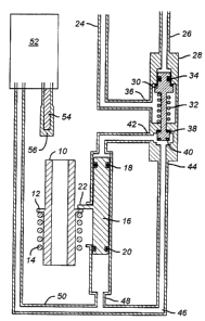
FIG. 1 illustrates a flow tube 10 having a circular flange 12 on its outer
periphery on which the power spring 14 delivers an upward force. The
subsurface
safety valve is presumed to be known by those skilled in the art. It is not
depicted in
FIG. 1. Those skilled in the art already know that the movement of the flow
tube 10
in a downward position which compresses the power spring 14 opens the
subsurface
safety valve. The reverse movement closes the subsurface safety valve.
The flow tube 10 is actuated downwardly by a dynamic piston 16 which has
an upper seal 18 and a lower seal 20. The dynamic piston 16 has a tab 22 which
bears
on flange 12 such that
-3c-
CA 02347997 2001-05-17
when the dynamic piston 16 is powered down, it compresses power spring 14
while moving flow
tube 10 downwardly.
Running from the source of hydraulic fluid pressure at the surface are
operating control
line 24 and engagement control line 26. Both lines 24 and 26 run into a
housing 28 in which
there is disposed an isolation piston 30 which is spring loaded by spring 32.
A seal 34 seals off
the engagement control line 26 so that pressure applied in line 26 will shift
the isolation piston 30
downwardly compress~n~; spring 32. The operating control line 24 enters
housing 28 at inlet 36.
The isolation piston 30 has an upper face seal 38 and a lower face seal 40. In
the position shown
in FIG. 1 the bias of spring 32 seats the upper face seal 38 against the
housing 28. The size of the
seal areas for upper face seal 38 and seal 34 are nearly the same putting the
isolation piston 30 in
pressure balance from applied pressures at port 36 from operating control line
24 in the position
shown in FIG. 1. Housing 28 also has outlets 4'' and 44. Outlet 42 is in fluid
communication
with dynamic piston 16 above seal 18 while outset 44 is in fluid communication
with dynamic
piston 16 below seal 20. There is a conduit 46 which branches into conduits 48
and 50. Conduit
48 leads to dynamic piston 16 below seal 20. Conduit 50 extends conduit 46
toward a coil 52.
Coil 52 has a filter 54 an~i is otherwise open at an outlet 56 to the
surrounding annulus (not
shown). Filter 54 keeps particulate matter out of coil 52 and conduit 50.
The significant components of the preferred embodiment now having been
described, its
operation will be reviewed in greater detail. In order to shift the flow tube
10 downwardlS~
against the bias of power spring 14 pressure is first applied in engagement
control line 26 which
downwardly shifts the isolation piston 30 against the bias of spring 32. This
downward
movement of isolation piston 30 brings the upper face seal 38 away from body
28 thus opening
-4-
CA 02347997 2001-05-17
up a flow path from inlet 36 to outlet 42. The downward movement of isolation
piston 30 ceases
when the lower face seal 40 contacts the housing 28 effectively shutting off
outlet 44.
Thereafter, applied pressure in operating control line 24 communicates through
outlet 42 to
dynamic piston 16 above seal 18 pushing downwardly and along with it tab 22.
Tab 22 in turn
bears on flange 12 which in turn pushes down flow tube 10 against the power
spring 14. The
subsurface safety valve is now open. The downward movement of the dynamic
piston 16 with
the lower face seal 40 against housing 28 will also result in displacement of
fluid in conduit 50
through coil 52 and out the filter 54 through outlet 56 to the annulus (not
shown).
In order to close ~ he subsurface safety valve, the pressure on the engagement
control line
26 is removed. The spring 32 which is sufficiently strong to resist the
hydrostatic pressure in
engagement control line 26 lifts the isolation piston 30 upwardly so as to
move the lower face
seal 40 away from housing 28 which in turn allows outlet 42 and 44 to
communicate through
housing 28 which has the effect of equalizing pressure on the dynamic piston
16 above and
below seals 18 and 20 respectively. When this occurs, the power spring 14 can
then move the
flow tube 10 upwardly to allow the subsurface safety valve to close.
Clearly, if pressure is lost due to leakage or other surface system failures
in the
engagement control line 26 the flow tube 10 will shift upwardly as pressure is
equalized across
the dynamic piston 16 due to spring 32 shifting the isolation piston 30
upwardly. A leakage
around the lower face :..eal 40 will equalize pressure on the dynamic piston
16 which will allow
the flow tube 10 to move upwardly. As previously stated, a leakage past seal
34 will prevent
movement of isolation piston 30 against spring 32 and should result in a
closure of the subsurface
safety valve by movement upwardly of the flow tube 10.
-5-
CA 02347997 2001-05-17
A leakage around seal 18 when the flow tube 10 is in the down position will
most likely
leak hydraulic fluid from outlet 42 into the tubular string which the
subsurface safety valve was
mounted. A leakage around seal 20 may allow the annulus to leak into the
tubular through outlet
56 if the annulus pressure exceeds the tubular pressure. If it is the other
way, and tubular
pressure will leak past seal 20 and into the annulus through filter 54. In the
event of leakage
around seal 18, the hydraulic fluid in the system coming from operating
control line 24 will leak
into the tubular as previously stated. However, as long as pressure is
maintained in the
engagement control line 26, the flow tube 10 may not rise under the force of
spring 14 if spring
14 is too weak to overcome the hydrostatic pressure in operating control line
24. Spring 14 does
not need to be sized to counteract the expected hydrostatic pressure for the
given depth in
operating control line 24 in that upon equalization around the dynamic piston
16 the power
spring 14 merely needs to overcome frictional forces and the weight of the
flow tube 10 to be
able to raise it up. In deep settings of the subsurface safety valve and in
view of the long stroke
required for the flow tube 10 having a power spring 14 sufficiently strong to
able to withstand the
hydrostatic in a control line such as operating control line 24 would be
difficult to configure in a
compact design. On the other hand, the stroke of the isolation piston 40 is
very short and
therefore, it is far easier to equip a spring 32 suitable for resisting
hydrostatic in engagement
control line 26 and keep the size of the spring 32 reasonable.
The design described in FIG. 1 has the advantage of not needing a pressurized
chamber,
but in turn it has the disadvantage of displacement of hydraulic fluid into
the annulus when the
dynamic piston 16 is stroked downwardly to open the subsurface safety valve.
Additionally, if
certain types of leaks develop, the arrangement in FIG. 1 will not necessarily
fail safe unless
-6-
CA 02347997 2001-05-17
pressure is removed from the engagement control line 26. For example, leakage
past seal 18
from outlet 42 will keep the flow tube in the down position until the leak
becomes catastrophic in
size or until the pressure is removed from engagement control line 26.
Those skilled in art will appreciate that the size in the power spring 14 in
the design of
FIG. 1 is independent ~f depth. On the other hand, the spring 32 must be
substantially stiff to be
able to withstand the hydrostatic in the engagement control line 26.
The spring 32 is far smaller and can be easily changed to reconfigure a
particular control
system to a depth to which it will be installed.
FIG. 2 represents an alternative embodiment which schematically illustrates a
coaxial
control line 58 which can simultaneously convey fluid pressure into conduit 60
and carry a
conductor which is optical electromagnetic or even hydraulic or electrical 62.
Conduit 60
branches into conduits 64 and 66. Conduit 64 leads to cylinder 68 in which is
a piston 70 with a
peripheral seal 72. Piston 70 is biased by a power spring 74. Upward movement
of piston 70
moves a flow tube (not shown) which in turn allows the subsurface safety valve
to close.
Downward movement of piston 70 compresses spring 74 and pushes the flow tube
down which
opens the subsurface safety valve in a known matter. Conduit 66 extends to a
control valve 76
which basically functions in two positions, open and closed. The signal to
open or close comes
from the conduit 78 through a conductor 62, if used, to the control valve 76.
Conduit 80 extends
from control valve 76 to the cylinder 68 below piston 70. Those skilled in art
can readily
appreciate that when the control valve 76 is closed and hydraulic pressure is
brought to bear in
conduit 64, the piston 70 is driven down compressing the spring 74, thus,
opening the subsurface
safety valve. In order to close the subsurface safety valve, the control valve
76 is opened from a
_7_
CA 02347997 2004-02-18
signal through conduit 78 which as previously stated can be any one of a
variety of different
signals. With the control valve 76 in the open position the pressure equalizes
between conduit 66
and 80 thus allowing the spring 74 to move the piston 70 upwardly to allow the
subsurface safety
valve to close. The alternative embodiment shown in FIG. 2 is again another
simplified process
which uses known coaxial technology to allow a conduit for communication of a
hydraulic signal
to be run coaxially or contemporaneously with a signal line which can be
optical,
electromagnetic, electrical, hydraulic or some other type of signal for
operating a bypass valve
between an opened and closed position. Those skilled in art will appreciate
that if the signal is
lost to the valve 76 it reverts to an open position which will close the
subsurface safety valve.
Additionally, loss of pressure in conduit 58 will also close the valve in the
normal operation.
Those skilled in art will appreciate that there are alternatives even in the
preferred
embodiment shown in FIG. 1 to the isolation piston arrangement. While the
isolation piston 30
has been shown to be hydraulically actuated, it can be actuated in a variety
of different ways.
The assembly of the housing 28 and isolation piston ~0 can also be replaced by
equivalent
structures which allow for the normal operation of the flow tube 10. Thus,
other types of valuing
arrangements which selectively allow pressurization of the dynamic piston 16
and equalization
around the dynamic pi ac>n 16 for normal and emergency operations are also
within the preview
of the invention.
The preceding description of the preferred and alternative embodiment is
illustrative of
the invention and is by no means a limitation of what can be claimed to be the
invention which
can only be seen from an examination of the claims which appear below.
_g_