Note: Descriptions are shown in the official language in which they were submitted.
CA 02348298 2001-04-25
WO 00/25883 1 PCT/SE99/01957
A NEW SYSTEM AND ITS UNITS.
The technical field
The present invention concerns a system for adsorption
(capture) of a compound that is present in a liquid flow
that pass through a fluidised bed. The invention also
concerns various parts of this system, such the as a
predistributor, a distributor, a vessel, a tilting device
etc. The invention also concerns processes that are adapted
to these parts.
By the term "capture" or "adsorption" is contemplated
that the compound becomes bound to the particles of the
fluidised bed by covalent bonds or affinity bonds, or by
physically entrapment within the particles. The binding may
be more or less reversible. Affinity bonds include binding
caused by bioaffinity interaction, ionic interaction,
hydrophobic interaction etc.
Binding as described above has previously been used for
removal and/or purifying: a) the compound that becomes
bound to the particles or b) a compound remaining in the
liquid, or c) the liquid as such. In case of item a) the
particles have been further processed in order to release
and possibly further purify the bound compound. In case of
items b) and c) the liquid has been further processed, for
instance in order to recover or remove some other compound
present therein.
Previous vessels for the above-mentioned processes have
been in form of cylindrical columns equipped with meshes at
the outlet end (collector end) and at the inlet end
(distributor end).
The collecfor arrangement typically has contained a plate
covered with a mesh on the side facing the vessel interior
and a collector chamber with one or more outlet openings in
the column end piece at the opposite side.
The distributor arrangement typically has contained a
distribution chamber with one or more inlet tubes and a
relatively thin perforated plate covered by a mesh resting
on distance holders on the side facing the vessel interior.
CA 02348298 2001-04-25
WO 00/25883 2 PCT/SE99/01957
The major functions of the meshes have been to hinder - -
fluidised particles from escaping the vessel and as a
support for particles packed to a bed.
US 4,450,082 describes a predistributor/distributor
system for packed beds.
The meshes used at either end of the vessel have had pore
sizes smaller than the particles used t.o form the bed
(packed bed or fluidised bed)
Particles with densities greater than the liquid have
been combined with upward flow and with the distributor
placed at the lower and the collector at the upper end of
the vessel. Particles with densities lower than the liquid
have been combined with downward flow and with the
distributor placed at the upper and the collector at the
lower end of the vessel. After adsorption in a fluidised
bed mode the particles have been allowed to sediment before
release of the captured (adsorbed) compound (packed bed
mode)
The term "release" includes desorption.
Capture of compounds in beds that are fluidised by an
upward liquid flow is described in WO 9100799 (Upfront
Chromatography), WO 9218237 (Amersham Phamacia Biotech AB),
WO 9520427 (Amersham Pharmacia Biotech AB), WO 9717132
(Amersham Pharmacia Biotech AB), WO 9833572 (Amersham
Pharmacia Biotech AB) and US 4,976,865 (Sanchez et al,
CNRS).
Drawbacks of previous techniques (distributor design)
In many applications a severe blockage has been
experienced of the inlet and outlet meshes. The main reason
has been clogging of feed material into the meshes, e.g.
cells, cell debris, aggregates etc. This leads to an
increased back pressure and maldistribution of the incoming
fluid. The effect will be channeling in the bed disturbed
plug flow and eventually the bed will collapse.
I similar effect is caused by air bubbles that are
present in the feed stream.
CA 02348298 2001-04-25
WO 00/25883 3 PCT/SE99/01957
Meshes nave a mechanical instability. Even if installed
as planar, they will tend to stretch and become wavy-like.
Non-planar meshes tend to disrupt a plug flow profile
created by a traditional distributor.
Distribution system in existing columns contains
horizontal surfaces. It has been experienced that this type
of surfaces often are difficult to clean from adhering
material, for instance cell and cell debris in case the
feed material contains fermentation broths and the like
l0 containing sticky components. Critical column parts are the
horizontal surface of the bottom end piece and surface of
the perforated plate (distribution plate) facing the bed
where there are "dead zones", i.e. zones with no active
flow of liquid and consequently no continuous rinsing.
Drawbacks without predistribution.
When the area of the distributor is increased and/or the
distributor area is divided into modules with separate
distribution chambers, there is a risk for uneven
distribution of flow across the area of the distributor.
This problem becomes particular important in case plug flow
is desired in fluidised beds.
Drawbacks of prior art vessel designs with respect to
emptying.
The traditional way of emptying vessels used in packed
bed as well as in fluidised bed has been to empty either
from the top or from the bottom while keeping the vessel in
an upright position. Bottom emptying many times has been
trough a valve in the side wall just above the bottom.
Previous methods have been rather complicated, many times
leaving bed residues in the vessels requiring extra
cleaning.
Drawbacks of previous designs of reactor vessels (fluidised
mode versus packed bed mode)
CA 02348298 2001-04-25
WO 00/25883 4 PCT/SE99/01957
If the bed is eluted and/or washed in an expanded mode
the volume of liquid needed will typically be at least
twice the packed bed volume, i.e, much more than for the
same procedure in packed bed mode. The reason is that the
liquid in an expanded bed will be highly turbulent when a
lighter buffer is trying to displace the denser sample. In
respect of process economics, the consumption of washing
buffer should be kept as low as possible.
The objectives of the inventive aspects.
~ To get a sanitary distributor design with a minimum of
dead zones and horizontal surfaces.
~ To generate the essential plug flow profile without using
a thin perforated plate and a mesh in which the pore size
is less than the particle size.
~ To reduce the risk for blockage of the distributor system
by increasing the smallest passage area considerably
compared to columns in which meshes are included.
~ To facilitate plug flow characteristics in
chromatographic beds.
~ To get a simple and mechanical robust. construction which
can stand an industrial environment.
~ To be scaleable (consistent performance) from small
laboratory columns/vessels to industrial columns/
vessels.
~ To have systems in which the need for large volumes for
washing and for release is lowered by making it easier to
change from packed to fluidised mode and the reverse.
~ To provide a system that facilitates emptying of vessels
used for capturing compounds to particles in packed or
fluidised bed mode.
By the term "essential plug flow" is contemplated a plate
number >_ 5 for an expanded bed/fluidised bed. The method
for measuring plate number is given in the experimental
part .
CA 02348298 2001-04-25
WO 00/25883 5 PCT/SE99/01957
Figures
All figures are cross sectional views, either from one
side, from above or from below. Parts in different figures
having analogous functions have the same reference
numerals.
Figures la-b show a system containing a cylindrical vessel
with a one-channel one-module distributor variant.
Figure la is a side view and figure lb is a view
from above at. the indicated level.
Figures 2a-b show a system containing a squaric vessel with
a multi-channel one-module distributor variant.
Figure 2a is a side view and figure 2b is a view
from above at the indicated level.
Figures 3a-b show a system containing a squaric vessel with
a multi-channel four-module distributor variant and
a predistribution system. Figure 3a is a side view
and figures 3b is a view from above at the
indicated level.
Figure 4 shows a system containing a vessel with circular
(column) or squaric cross sectional area having a
traditional one-module distributor variant and a
predistributor.
Figures 5a-f show a system containing preferred variants of
the vessel, the distributor with check valves, the
collector, the predistributor and the tilting
device. Figure 5a is a side view of the vessel with
no check valves shown, figures 5b-f are blown up
side views (b, c and f) or a view from above (d)
and from below (e). Figure 5b shows the top part of
the vessel, figure 5c one alternative for a check
valve, figure 5d a section of the distributor,
figure 5e the branchings in a network of pipes in a
predistributor and figure 5f a constricted part of
the pipe net-work.
Figures 6a-b show the design of an alternative check valve
in an open and a closed position, respectively.
CA 02348298 2001-04-25
WO 00/25883 6 PCT/SE99/01957
Figures 7a-d show a tiltable system in fluidised and packed
bed modes with particles having densities greater
than the fluid (figures 7a-b, respectively) and
with particles having densities less than the fluid
(figures 7e-d, respectively).
Figure 8 shows a system containing two vessels: a first
tiltable vessel I for fluidised bed mode and a
second vessel II for packed bed mode.
Figure 9 shows a system in which there is a common tiltable
l0 integrated unit containing a first vessel I for
fluidised bed mode and a second vessel II for
packed bed mode.
Figure 10 shows a system in which there are a first
tiltable vessel I for fluidised bed mode, a second
vessel II in form of a hydrocyclone and a third
vessel III for packed bed mode.
Figures lla and llb show alternative designs of the
distributor block with a distributor chamber and
liquid connections from the chamber to the block.
The term "cross sectional area" means an area that is
perpendicular to the flow direction, if not otherwise
specified.
The main inventive aspects
System aspects: One main aspect of the invention is a
system suitable for the capture of a compound present in a
liquid by particles of a fluidised bed. The characterizing
feature is that the system comprises at least one unit of
the inventive system described herein.
The distributor and the tilting device of the invention
can be used with vertical flow that can be either upward or
downward. The predistributor can be applied also to other
flow directions.
The predistributor and distributor can also be used for
beds in form of porous monolithic plugs. The predistributor
will also function for packed beds.
CA 02348298 2001-04-25
WO 00/25883 ~ PCT/SE99/O1957
Process aspects: These relate to processes for removal
and/or purifying a compound from a liquid by allowing the
liquid to flow through a vessel containing a fluidised bed
of particles that are capable of capturing the compound.
The characterizing feature is to use one or more units of
the inventive system described herein.
Some of the process aspects will also be useful in packed
beds and porous monolith beds in form of plugs. See below.
l0 The liquids used may be aqueous, i.e. water or mixtures
containing water and one or more water-miscible liquids.
Also non-aqueous liquids may be used.
General description of the predistributor
The predistribution system of the invention is
illustrated in figures 3-5. The system comprises a pump
(1), a common inlet tube (2) branching into two or more
open end pipes (3) directing flow to a respective subarea
of a distributor. The characterizing feature is that there
are means associated with each end pipe, which constrict
the flow such that a significant pressure drop is created
across the end pipes when the liquid is passing through.
In the context of the predistributor "pipes" or "pipe"
designates flow passages in general. The terms include
channel(s), tube(s), conduits) and other kinds of flow
passages that have the analogous function.
CA 02348298 2001-04-25
WO 00/25883 g PCT/SE99/01957
General description of the distributor
The inventive distributor is illustrated in figures 1-3
and 5. The distributor is built up of a block that may have
a size from true plate dimensions up to true block
dimensions. Open channels for liquid flow are passing
through the plate. Thus the inventive part of the
distributor is a distributor block (9) having one outlet
side (5) and one inlet side (6) that are essentially
parallel to each other. Between the two sides there are one
or more evenly spread out essentially parallel identical
open channels (7) that are perpendicular to the two sides
(5,6) and stretching from one side to the other. The
characterizing feature is that each channel (7) comprises a
narrow inlet section (7a) next to the inlet side (6) of the
distributor block (4) and an outlet section (7b) which is
widening towards the outlet side (5) of the distributor
block (9).
The distribution system.
The distribution system comprises the inventive
distributor and optionally a predistributor that may be our
novel predistributor.
Three versions of our distribution system are shown in
figures 1-3.
Figure 1 shows a one-module distributor variant applied
to a small cylindrical vessel (8). In principle no
predistribution is required. This variant is primarily
intended for thinner vessels/columns, for instance with
cross sectional areas corresponding to squares with sides <_
20 cm. Figure 2 shows a one-module distributor variant
intended for larger vessels (8), for instance with cross
sectional areas corresponding to squares with sides >_ 10
cm. A predistributor is normally not required. Figure 3
shows a variant in which the distributor is modular, i.e.
contains two or more equal parts (modules) each of which
having its own distribution chamber (9a-d, only 9a-b shown)
CA 02348298 2001-04-25
WO 00!25883 9 PCT/SE99/01957
and distributor block (4a-d). To this variant of the - -
distributor there should be connected a predistribution
system which divides and distributes an incoming liquid
flow to different modules/subareas of the distributor.
Modular distributors are intended for larger vessels, for
instance with cross sectional areas corresponding to
squares with sides >_ 40cm. The number of modules in one
distributor depends primarily of the size of the vessel,
and may for instance be 4, 16, 64 etc. in case the column
is squaric.
Figures 1-3 further show a common inlet conduit (2) with
a pump (1), a predistributor (in figure 3 only represented
by a branching of the inlet conduit into the end pipes
(3)), one or more distribution chambers (9 and 9a-d, only
in figures 2 and 3, respectively) with an inlet opening
(11, figures 2 and 3) and one or more outlet openings (12),
a distributor block (4) with one or more channels (7), and
the vessel (8) to which the liquid is to be distributed.
Across the vessel from the distributor end there is the
collector arrangement. In figures 1-3 the collector
arrangement is illustrated with a relatively simple
construction consisting of the inner side (14) of the end
piece (13) and a central outlet opening (15) connected to
an outlet tube (1&). The opening (15) may be equipped with
a valve function. The incoming liquid will pass the parts
of the vessel in the same order as they are written above.
The channel/channels (7) in the distributor block (4)
enables/enable liquid flow to enter the vessel (8) from the
incoming conduit without any distribution chamber (figure
1) or via a distribution chamber (9 and 9a-d, figures 2 and
3, respectively). Each channel (7) has a narrow inlet
section (7a) starting from the inlet side (6) of the
distributor block (4) and an outlet section (7b) widening
towards the outlet side (5) of the distributor block (4).
The cross sectional area of the narrow inlet section (7a)
is typically circular although also other geometrical forms
may be used.
CA 02348298 2001-04-25
WO 00/25883 10 PCT/SE99/01957
The length of the widening (7b) should be such that the -
outlet of the channels (7) covers as much as possible of
the outlet end area (5) of the distributor block (4).
The widening outlet section (7b) may be conical,
pyramidal etc and forms therebetween. The widening may
start as a cone with a circular cross sectional area
closest at the narrow inlet section (7a), then continuously
change to a rectangular area, such as a squaric area (17,
7b in figures 2b and 3b). The widening angle (18), i.e. the
angle between the wall of the widening outlet section (7b)
and the intended flow direction, may be from just above
zero, e.g. > 0.5°, such as > 2-3°, to <: 75°, such as <_
50°
or even <_ 20°. In order to optimize for plug flow in the
channel outlet areas the angle should be rather smooth with
an angle <_ 20°, such as <_ 10°, with preferred values
typically being around 5-8°. The widening may be
symmetrical or unsymmetrical around the central axis of the
channel.
The ranges for the angels given above primarily refer to
the angel at the borderline between the narrow inlet
section (7a) and the widening outlet section (7b). At the
opening rim in outlet side (5) the angels can be
considerably higher. Preferably the angel should be
continuously increasing when going upwards toward the
outlet surface (5) (convex surface). In this variant the
starting angel at the interior of the widening section (7b)
may be as low as zero and then increase in the lower part
of the widening section (7b) in order to facilitate the
formation of early plug flow. The shape of outlet section
(7b) may be bell-like (continuous line) or preferably
trumpet-like (broken line). See figures lla and b. The
widening section (7b) may change form (both along the Y-
axis and in the x-y-plane) at the outlet side (5) in order
to accomplish an optimal dense packing of the opening areas
(17) in the outlet side (5).
CA 02348298 2001-04-25
WO 00/25883 11 PCT/SE99/01957
Channel outlet areas (17 figures 2b and 3b) that are - -
squaric or hexagonal or of any other form permitting edge-
by-edge packing are preferred. The reason is that the
openings then will be able to occupy essentially 100 0 of
the area of the outlet side of the distributor block facing
the interior of the vessel. This geometrical arrangement
will also assist in optimizing for plug flow across the
cross sectional area at the outlet side (5) of the
distributor. A squaric, hexagonal etc form of the full
outlet side (5) of distributor block or modules thereof is
therefore preferred.
Larger widening angels, for instance > 10° such as > 15°,
will often require a higher density of channels and
channels with thinner narrow sections (7a) in order to
create a pressure drop over the block/plate (4) for
sufficient plug flow characteristics in the expanded bed.
The low widening angle (18) and the pressure drop
requirements for optimizing to plug flow close to the
outlet side (5) of the distributor (4) imply that the
distributor block typically will have true block
dimensions. This is contrary to the prior art methods for
flow optimisation, which has resulted i.n a thin plate
character of the corresponding part of the distributor.
In case the narrow inlet sections (7a) are short compared
to the widening outlet section (7b), an insignificant or
obsolete pressure drop across the distributor block may be
compensated by attaching pressure drop means (68a, 6B'a,
68b, 68'b), figure 11.) to each inlet opening (12). See
further figure 11. This extra pressure drop means may be
inserted as soon as the pressure drop across the
distributor block (4) is not sufficient.
Figure 3 shows a distributor built up of four modules
(chambers 9a-d plus distributor blocks 4a-d). Each modules
may be connected to one end pipe (3) of the predistribution
system. In less preferred variants there may be two or more
end pipes connected t.o each module. There may be a
sprinkler arrangement in the inlet openings) of a
CA 02348298 2001-04-25
WO 00/25883 12 PCT/SE99/01957
distribution chamber (for instance as described (20) for -
the system in figure 4).
Figure lb-3b illustrate that the cross sectional area of
the vessel and the distributor may be circular (figure 1b)
or squaric (figures 2b and 3b).
Figure 4 shows our novel predistribution system (10)
applied to a larger vessel (8} that may be cylindrical
(column) or have a rectangular, such as squaric cross
sectional area. The vessel contains a matrix (21) that may
be a packed bed or a porous monolithic plug. By the term
"larger column" is contemplated that the cross-sectional
area should be greater than for a column with a radie >_ 20
cm. The fluid communication between the distribution
chamber (9) and the bed (21) is via a mesh (22), possibly
combined with a thin perforated plate (not shown) with
holes passing through the plate and placed between the mesh
(22) and the distributor chamber (9). On top of the bed
(21) there is placed a second mesh (22a). For this type of
vessels one can envisage distributors consisting of modules
each of which having their own distributor chamber and
mesh, possibly combined with a distributor plate. The
predistribution system is of the same type as shown in
figure 3. For beds in form of porous monolithic plugs
either or both of the meshes (22 and 22a) may be replaced
with a perforated plate, for instance with a slot between
the mesh and the inlet side of the bed. There are sprinkler
means (20) in the distribution chamber (9)
Figures 11 show an enlarged section of two alternatives
of the distributor block (4). The alternatives have a
widening outlet section (7b) that is convex in its lower
part. A trumpet-like (broken line) and a bell-like
(continuous line) shape are indicated. The narrow inlet
section (7a) is relatively short and have a relatively
large cross sectional area, which means that the pressure
drop over the narrow inlet section (7a) in practice will be
obsolete (null) or insignificant. This may be compensated
by extra pressure drop means that in figure 11 is
RECT(FIcD SHEET (RULE 91)
CA 02348298 2001-04-25
WO 00/25883 13 PCT/SE99/01957
illustrated as a channel (68a), figure 11a) or as a tube- --
(68b, figure 11b) that may be flexible. Also other
alternatives for flow passage are possible. The flow
passage (68a, 68b) connects the distribution chamber (9')
to the inlet opening (12) of the narrow inlet section (7a).
The distribution chamber (9') in turn may be connected to a
pump and a liquid reservoir, possibly via a predistribution
system (not shown) in analogy with the design given in
figures 2-3 and 5. The reference numerals 68'a and 68'b
indicate additional flow passages between one and the same
chamber (9') and other openings (12) in the block (4). Also
this is in analogy with the connections between the
distribution chamber (9, 9a, 9b . .) and the vessel
interior (8) in figures 2-3 and 5. The geometrical design
of the openings (17) should permit dense packing in the
outlet side (5) as discussed above for figures 2-3 and 5.
Figures lla-b also illustrate that there may be a check
valve in which the valve function may be based on a movable
body (29). The check valve may also have valve closing
means (30) and retaining means (not shown). For various
designs of check valves see figures 5c-d and figures 6a-b.
Function of the distribution system.
The actual distribution of the liquid takes place in the
distribution chamber (9). The liquid flow that enters the
chamber from the predistribution system (10) will
distribute evenly throughout the chamber due to the flow
resistance in the narrow inlet section (7a) of the
channels. This channel part is sized to provide a
sufficient pressure drop in order to resist possible
pressure fluctuations within the vessel (8). The widening
angel (18) of the outlet sections (7b) of the channels is
very smooth in the preferred variants in order to prevent
energy losses due to creation of extra turbulence in the
outlet of the channels. The end pipes (3) of the
predistributor system (10) assist in distributing the
liquid evenly to the subareas/chambers (9a-d) of the
distributor and to the narrow inlet sections (7a). The
RECTIFIED SHEET (RULE 91)
CA 02348298 2001-04-25
WO 00/25883 I4 PCT/SE99/01957
final distribution into the vessel (8) is through the - -
widening outlet sections (7b) of the channels.
Detailed description of the predistributioa system.
The details of the predistributor system are illustrated
in figures 5e-f. The predistributor is built up of a pipe
network that comprises a pump (1, only shown in figures 3
and 9), a branched network of pipes (10) ending in at least
one pipe (3) per subarea of the distributor. Two types of
"subareas" are illustrated in figures 3 and 4:
a) the distribution chamber of a distributor module and
b) the part area of the inlet end of a common distributor
block, plate or mesh to which an end pipe (3) direct
flow.
The various pipe branches are narrowed down when going from
the pump (1) to the end pipe (3). See figure 5f where the
inlet conduit (2) is thicker than the first pipe parts (23)
that are thicker than the second pipe part (25) that are
thicker than the end pipes (3). Numerals (24) and (26)
represent branchings. The last piece of pipe (3) comprises,
between its outlet (11) into the chamber (9) of a module
and the last branching (26), a part (19) that has an inner
diameter that is less than the rest of the pipes in the
network. This constricted part (19) of each end pipe will
create a significant pressure drop compared to all other
pipe parts. The pressure drop will stabilise the
distribution of liquid to the chambers (9a,b,c....). Small
pressure fluctuations within the distribution chambers)
(9a,b,c....) and the vessel (8) will not affect the
distribution if the pressure drop is selected high enough.
The pressure drop over each end pipe should be
essentially equal. This may be achieved by letting the end
pipes have essentially the same length and inner diameter.
Theoretically this may also be achieved for end pipes of
different lengths in case the inner diameter is varied
appropriately.
CA 02348298 2001-04-25
WO 00/25883 15 PCT/SE99/01957
The pipe network may have branchings on several "levels",--
meaning that branches of the incoming conduit (2) in turn
may branch one or more times before ending in an end pipe
(3). See figure 3f.
Each narrow end pipe (3) may be equipped with sprinkler
means (not shown) as described above in figure 4 (numeral
20).
Measures of important features.
l0 The pressure drops caused by the end pipes (3) and by the
narrow inlet sections (7a) of the channels depend on i.a.
flow rates. Typical flow velocities for fluidised beds are
> 25 cm/h. For higher productivities the goal is to go over
at least 70 cm/h with the understanding that the higher
velocities will require denser particles. At the present
time a preferred range of 70-3000 cm/h can be envisaged.
The pressure drop will increase with decreasing cross
sectional area and increasing length of both the narrow
inlet sections (7a) of the channels and the constricted
parts (19) of the end pipes. Increasing number of channels
(7) will decrease the pressure drop.
Typically the cross-sectional area of the narrow inlet
sections (7a) will correspond to a circle having a diameter
selected in the interval 0.1-20 mm. The preference is for
0.4-10 mm. The cross-sectional area is preferably in form
of a circle. The length will typically be in the interval
1-500 mm, with preference for 1-200 mm. The number of
channels per distributor module are preferably such the
their outlet areas (17) are as dense packed as possible.
Typical desired pressure drop values for the narrow inlet
sections (7a) are often selected in the interval 10-10000
pascal. An insufficient pressure drop may be at hand in
case the narrow inlet sections (7a) have a length and a
cross-sectional area that correspond to the lower
respective upper part of these ranges. In these cases an
insufficient pressure drop may be compensated by connecting
separate pressure drop means to each of the openings (12).
CA 02348298 2001-04-25
WO 00/25883 16 PCT1SE99/01957
The cross-sectional area of the constricted part (19) of
end pipes (3) should correspond to a circle having a radie
in the interval 1-50 mm, with preference for 3-30 mm. The
length of the same parts is in the interval 1 cm - 1 m,
such as 5 cm - 30 cm. The cross-sectional area is
preferably in form of a circle. Typical pressure drop
values are in the interval of 100 pascal - 2 bar.
These values and features also apply, where appropriate,
to predistributors and distributors to be used for packed
l0 beds and porous monolithic plugs.
The above-mentioned features are interrelated in a
complex way and are also dependent on the size of the
vessel, the type of bed, distributor area, distributor
chamber design etc which means that they need to be decided
on a per case basis. As a general rule of thumb the
pressure drop over the end pipes (3) should be much higher
than the pressure drop over the narrow outlet sections
(7a), for instance more than 5 times, often more than 10
times.
Distribution chamber arith sprinkler means.
This variant is illustrated in figure 4. It is a
distribution chamber (9) having one (2, figure 2) or more
(3, figures 4) inlet conduits. The chamber (9) is in liquid
communication with a vessel (8) intended for carrying a
chromatographic medium (21) in form of particles as defined
above or in form of a monolithic plug having flow through
pores. The means for liquid communication between the
interior of the vessel and the distribution chamber may be
via a net/mesh (22) possibly combined with a perforated
plate or block having open through passing channels. The
net/mesh is in the latter case positioned between the
interior of the vessel and the perforated plate or the
block. Liquid communication may also be via our inventive
distributor black without any net or mesh. The
characteristic feature is that each inlet conduit (11) is
equipped with sprinkler means (20). Typically the end of
CA 02348298 2001-04-25
WO 00/25883 1 ~ PCT/SE99/01957
each inlet conduit (11) has a cap and holes (27) placed ~ -
circularly in the wall of the end of the conduit just
before the cap. The holes should permit even radial
distribution of incoming liquid. The distribution should be
perpendicular to the flow direction in the conduit
concerned. The size, amount and total area of the holes are
selected such that there will be an increase in flow
velocity when the liquid is passing through the holes.
The inlet conduit (11) may be one of the end pipes (3) in
the inventive predistribution system described herein (see
figure 3) but equipped with sprinkler means (20). The inlet
conduit may also be the common inlet (2) to the
distribution chamber of a one-module distributor of the
inventive type (figure 2) or of the corresponding
conventional type for fluidised beds.
The primary advantage of this construction is that it
will facilitate even distribution of liquid to channels (7)
and possibly assist in keeping the chamber clean from
sticky components that may be present in the feed material.
Distributors r~ith check valve.
The distributor in this aspect comprises a block/plate
which has two essentially parallel planar sides (5 and 6,
respectively) and one or more, preferably two or more,
parallel open channels (7) that are perpendicular against
the sides (5,6). When in use the block/plate is placed in
the inlet side of a chromatographic vessel as described
above. The inventive distributor/block in this aspect of
the inventive system is characterized in that each channel
is equipped with a check valve, for instance as described
below.
The number of channels and their, size, length and form
should be selected to enable plug flow as described above.
In case the channels contain no widening, the length and
width of the channels can be selected as outlined above for
the narrow inlet sections (7a). Appropriate pressure drops
are in the interval 10-10000 pascal. If needed the channels
CA 02348298 2001-04-25
WO 00125883 18 PCT/SE99/01957
may be combined with extra pressure drop means as discussed-
above. See for instance figure 11.
Preferred distributor blocks.
In a preferred distributor variant (illustrated in
figures 5a,c,d) each channel comprises a check valve
function, preferably located between the narrow inlet
section (7a) and the widening outlet section (7b) or in the
lowest part of widening outlet section. This function
comprises a part of the channel (check valve space) (28).
The check valve space (28) is equipped with valve means
that keeps the channel open when forward flow is applied
and closed when no flow or back flow is at hand. The check
valve space may be a recess (28) coaxial with and located
at the exit of the narrow inlet section (7a) next to the
start of the widening outlet section (7b). The valve means
may comprise a body (29) that has such a size and form that
it is movable within the check valve space (29) and permits
liquid to pass between the body and the walls of the check
valve space (part of the channel walls). The body is
movable within the check valve space between
a) a first position which contains 'valve closing means
(30) that, when the body is engaging this means, the
channel will be closed, and
b) a second position at which the movement of the body
is stopped by so called retaining means (31) thereby
preventing the body from escaping the space and enter
the vessel while permitting flow to pass through.
The valve means in a preferred variant thus comprises the
movable body, the closing means and the retaining means.
The means in the first position may be a smoothly
constricted part of the check valve space, for instance its
bare inlet opening (30). The retaining means may be
protrudes (31) attached to the outlet opening of the check
valve. Exemplary protrudes are pegs, indentations, a net or
the like which will catch or prevent passage of the body.
An alternative for protrudes are means that anchor the body
CA 02348298 2001-04-25
WO 00/25883 19 PCT/SE99/01957
(29) to the check valve space (28). In this case the -
retaining means may be elastic or resilient anchors, for
instance string-like. For still another alternative see
figures 6a-b. The liquid that is to pass through the check
valve often contains sticky particulate materials. This
means that the retaining means and closing means shall
occupy as little as possible of the cross sectional area of
the check valve space.
The movable body is selected to have a size and form such
that it
a) together with the closing means (30) in the first
position is able close the channel (7), and
b) when moved to the second position, can not pass
through but still permit liquid to pass through.
The size and form of the body, the closing means and the
retaining means should be selected such that the body is
able to move from one position to the other by changing
from forward flow to no flow or to back flow or the
reverse. Opening and closing may also be controlled by
external means.
The movable body (29) may have various physical shapes,
such as pyramidal, spherical, conical, sheet-like etc. The
proviso is that the selected form should be able (a) to
match tightly to the the closing means and (b) to be
retained by the retaining means without preventing flow to
pass by.
In case the flow is upward, it is preferred to select a
body (29) having a density greater than the density of the
liquid used. The flow pressure will lift the movable body
(29) and free it from the closing means (30) of the check
valve space (28). When flow is stopped or back flow is at
hand the gravitational force and/or back flow will press
the body (29) to the closing means (30) thereby closing the
valve. In case the flow is downward it is preferred to
select a movable body (29) that has a lower density than
the liquid. The same principles apply in this variant as in
the case with upward flow. Downward flow will open the
CA 02348298 2001-04-25
WO 00/25883 20 PCT/SE99/01957
valve. When downward flow is stopped the buoyancy force-of--
the liquid will close the valve. One can also select to
drive and/or support the closing and opening functions by
external means, such as magnetic and mechanical means.
In a preferred variant (also shown in figure 5a-c), the
distributor block may comprise two block parts: the inlet
block part (33) comprising the narrow inlet sections (7a)
and the outlet block part (32) comprising the widening
outlet sections (7b) of the channels (7). The different
l0 channel sections are equally spaced in their respective
block part so that, when the outlet black part (32) is
placed on the inlet block part (33), channels (7) can be
formed. In case check valve spaces (29) are to be included
they may be formed as a respective recess coaxial with a
channel opening in one of block parts (32,33) or formed
from a recess in each of the block parts (32,33). Valve
means, such as a movable body, retaining means and closing
means may then be located to the recesses as found
appropriate.
In one check valve variant the retaining means is a
tightening sheet material placed between the block parts
(32 and 33). This sheet material may have holes matching
the channel part openings in respective block part. The
peripheries of the holes are then equipped with retaining
means in form of protrudes, pegs, indentations and the like
as described above. A similar effect may be achieved as
illustrated in figures 5c-d by having the rim of the recess
equipped with a minor recess (34) in which an o-ring (35)
is placed. The o-ring may be equipped with inwardly
directed retaining means (31).
Another alternative construction of the distributor block
is to manufacture it from three block parts: one inlet part
comprising the narrow inlet sections, one middle part
comprising the check valve spaces and one outlet part
comprising the widening outlet sections.
CA 02348298 2001-04-25
WO 00/25883 21 PCT/SE99/01957
Manufacturing of the distributor block from block parts
is also applicable to distributors without check valve
function.
Tightening between the different block parts may be
achieved in a manner known per se, for instance by placing
the tightening resilient sheet material or o-rings between
the various block parts as described above.
An alternative check valve with a movable body is shown
in Figures 6a-b. Figure 6a shows the valve in an open
position and figure 6b in a closed position. This check
valve comprises a check valve space (28) that is part of a
channel (7). The closing means is a more or less cup-like
structure (30) firmly placed in the check valve space with
its open end turned downstream in the direction of the
vessel (8). The structure (30) has flow through holes (35)
and/or provides a space between its periphery and the
channel wall. On the downstream side (concave side) of the
structure (30) is placed a movable body (29) in form of a
resilient sheet that is able to tighten:ingly cover this
side of the structure and possibly extending a bit up on
the channel wall. At forward flow (figur 6a) the sheet is
bent forward opening the flow through passages (35). At
zero or back flow (figure 6b) the resilient sheet returns
thereby tightening the flow through passages (35). In this
variant the cup-like structure (30) functions as closing
means and the part of the body attaching the body to the
structure as retaining means (31). The inlet and outlet of
the check valve space becomes redundant in the simplest
variant. This type of check valve is particularly adapted
to be placed in the narrow inlet section (7a) of the
channels.
The check valve space (29) may be located
(a) between the narrow inlet section (7a) and the
widening outlet section (7b),
(b) in the narrow inlet section (7a) or in close
proximity thereto in the distribution chamber, and
(c) in the widening sections (7b).
CA 02348298 2001-04-25
WO 00/25883 22 PCT/SE99/01957
Alternative c) means that the check valve space (29) may -
be located close to or in the vessel (8). However, the
closer to the vessel (8), the retaining means is located
the higher the risk for disturbances in plug flow. In case
the retaining means is located in the vessel and the body
is non-anchored, the spaces between the retaining means and
the rims of the openings of the widening section have to be
less than the size of the body. For retaining means in form
of nets, the meshes shall be smaller than the body.
The various block parts used in the distributor block of
the invention may be manufactured from plastics, such as
polypropylene, or metal material, such as stainless steel.
The various channel parts may be formed by the use of, for
instance, a laser, water drilling, or mechanical drilling
or combinations thereof. Water drilling in combination with
mechanical drilling is experienced to be a particularly
good variant for plastics. The sheet material placed
between block parts o.f the distributor may be manufactured
from elastic and/or resilient materials, such as rubber.
The movable body may be manufactured from steel or glass
or plastics, while remembering selecting material so that
the body can move correctly when flow is applied or
disrupted.
The vessel used for capture
The adsorption vessel is defined by a distributor block
(4 in figures 1-5) at the inlet, a collector arrangement at
the outlet and walls (36) between the collector arrangement
and the distributor block. The walls are perpendicular at
least in relation to the distributor block. The distributor
may be of the same type as described above for our
inventive distributor. See figures 1-3 and figure 5a. In
some variants the distributor may be a mesh. See figure 4.
The size and form of the cross sectional area of the vessel
should be the same as for the distributor block i.e.
CA 02348298 2001-04-25
WO 00/25$83 23 PCT/SE99/01957
circular, rectangular (such as squaric), hexagonal etc. -See-
above.
The collector arrangement may be of the conventional
type. It may also be as suggested in figures 1-3.
Figures 5a-b illustrate that the collector arrangement
may comprise an end piece (13) and a mesh (37) on the side
(14) facing the vessel interior. A perforated plate may be
placed therebetween (not shown). Between the end piece and
the mesh there is a slot (38). The side of the end piece
i0 (14) facing the mesh (37), the mesh (37) and, if present,
the perforated plate may have a slightly conical form
turning outward from the vessel interior and fitting
physically into each other as shown in figures 5a-b. In
order to maintain the slot (38) well-defined, the end piece
surface (14) towards the vessel interior may have ridges or
other protrudes (not shown) on which the mesh is resting.
Both the mesh (37) and, if present, the perforated plate is
covering essentially the complete area of the outlet end of
the vessel. The slot (38) may have an opening (39) in the
end piece (13), which in turn is connected to an external
tubing (40) for guiding liquid away from the vessel when
the vessel is run, for instance with particles in fluidised
mode. The mesh (37) and, it present, also the perforated
plate may have an opening (41) that are connected to an
opening in the end piece. This opening in the end piece may
be the same as opening (39). The opening (41) may carry a
valve (42) and a thereto separately linked external tubing
(43) for unloading and loading the vessel, for cleaning
purposes, and/or for letting the liquid flow out during
fluidised bed operations (for instance capture, washing,
releasing, equilibration and cleaning). The valve may be a
nozzle, for instance constructed as described in US
5,213,683 (Chromaflow) and US 5,282,973 (Chromaflow) and w0
9810451 (Euroflow) which are hereby incorporated by
reference. The external tubings (40 and 43) may contain one
or more two-way and/or three-way valves.
CA 02348298 2001-04-25
WO 00/25883 24 PCT/SE99/01957
The valve (42,15) shown in figure 5a-b can be envisaged -
particularly useful in the context of present inventive
distributor design. It has two positions (open and closed)
and may contain a movable piston like device (44) equipped
with a disc (45) and placed in opening (41). The disc has
such a form and size that it will tighten opening (41) when
the valve is in a closed position. In the open position the
operations described in the preceding paragraph may take
place (loading, unloading etc). Opening and closing may be
achieved by adjusting the disc-equipped piston like device
(44+45) and opening (41) relative each other so that liquid
is able to pass or not to pass between disc (45) and the
rim of opening (41).
The opening (39) in the end piece (13) is preferably
ring-formed with opening (41) coaxially located inside it.
The openings (39) and (41) are preferably located
centrally in the end piece (13).
Valve constructions having essentially the corresponding
functionality can also be set up without a perforated plate
or a mesh.
As illustrated in figures 5a, the outlet end of the
reaction vessel may be equipped with a gel sensor (46) for
determining/detecting the height of a fluidised bed and/or
the bed homogeneity. This may often be appropriate because
there will be advantages with running fluidised bode mode
operations in the vessel with the valve (42) in an open
position. By then controlling, for instance, bed height by
the use of the signal from the gel sensor, it will be
possible to adjust the flow velocity such that no
significant amount of particles will escape out through
opening (41).
The tilting aspect
In its broadest sense this aspect solves problem with
respect to emptying vessels used in capturing a compound by
particles in packed or fluidised bed mode.
CA 02348298 2001-04-25
WO 00/25883 25 PCT/SE99/01957
A switch from fluidised bed mode to packed bed mode has
easily been accomplished in the vessels used so far by
allowing the particles to sediment and reverse the flow
direction. This will hardly be feasible with the best
variants of our novel distributor design.
The broadest aspect of the inventive tilting device
comprises a vessel containing particles, either in
fluidised bed or packed bed mode. A compound present in the
in the liquid passing through the bed may then be captured
by the particles. The vessel may be as described above, for
instance in figures 1-5, but may also be of a traditional
type. The characterizing features are that the vessel
a) has an end piece (13) at the top equipped with a valve
(15), preferably located centrally, permitting loading
and unloading the vessel etc, and
b) is placed, for instance as illustrated in figure 5a,
in a stand (47) permitting vertical tilting 180° from
an upright position.
In order to facilitate vertical tilting the vessel may be
equipped with one or more elements I (48) for attaching the
vessel to the stand (47), and the stand (47) may be
equipped with one or more elements II (49) for attaching
the stand to the vessel. Elements I (48) may comprise
shaft-like means or other support means for Elements II
(49). Elements II (49) may comprise means that are
complementary to the means of elements I (48), e.g. if
elements I comprise shaft-like means then element II
comprise support means fitting to the shaft-like means of
elements I, or vice versa. An example of support means for
shaft-like means is bear-rings.
A packed or fluidised bed in a suitable column/vessel
placed in an upright position in the arrangement described
in the previous paragraph can be tilted 180°. After tilting
the vessel can be easily emptied by opening the top valve
(15) (now at the bottom), possibly by flushing liquid into
the vessel through the distributor (now at the top). In
case the vessel is according to figure 5, flushing liquid
CA 02348298 2001-04-25
WO 00/25883 26 PCT/SE99/01957
through the mesh (37) (now at the bottom) may assist
emptying, in particular in case the particles have caked or
lumped together. Breaking up of cakes, lumps and the like
may be further assisted by pulsing liquid flow into the
vessel through valve (42) (with no flow entering the vessel
through the distributor). In case the interior side (14) of
the end piece and, if present, also the mesh (37) and an
optional perforated plate, are slightly conical as
described in connection with figure 5, emptying will be
further facilitated.
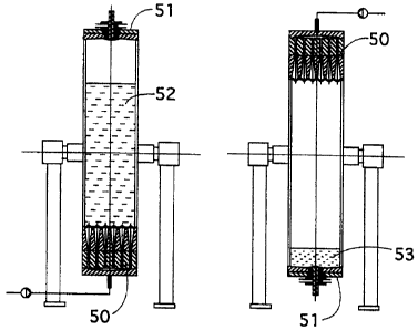
Vertical tilting 180° of vessel (8) placed in a stand
(47) as described in connection with figure 5, will permit
switching between fluidised bed and packed bed modes. See
figure 7a-d in which the distributor end is (50), the
collector end (51), the fluidised bed (52) and the packed
bed (53) .
Figure 7a-b shows the case when the particles have a
density that is greater than the flowing liquid. The
fluidised bed (52) expands from the lower part of the
vessel and the distributor (50) will be down (inlet end),
the collector (51) up (outlet end) and the flow upward
(figure 7a). The packed bed position is the reverse with
distributor (50) up , collector (51) down and downward
flow. The particles will sediment (53) at the collector end
(figure 7b).
Figure 7c-d shows the case when the particles have a
density that is lower than the flowing liquid. The
fluidised bed (52) expands from above. The fluidised bed
(52) position is with the distributor (50) up (inlet end),
the collector (51) down (outlet end) and downward flow
(figure 7c). The packed bed (53) position is the reverse
with the distributor (50) down, the collector (51) up and
upward flow. The particles will float and form a packed bed
(53) beneath the collector end (51) (figure 7d).
RECTIFIED SHEET (RULE 91 )
CA 02348298 2001-04-25
WO 00/25883 2~ PCT/SE99/01957
Packed mode operations can be run directly after tilting-
from the fluidised bed position.
Other column arrangements utilizing the tilting device of
the invention.
The term "packed bed position" contemplates also a
position in which particles are to be transferred from the
tiltable vessel (vessel I) to a second vessel (vessel II).
This latter vessel (II) is configured for packed bed
treatment of the material (e. g. release, cleaning,
regeneration etc) or permits physical separation of the
particles from the liquid prior to letting them form a
packed bed in still another vessel (vessel III). Vessels I
and II may be connected to each other via a three-way valve
in which a first port opens to vessel I, a second port to
vessel II and a third port to the outside, for instance via
a second three way valve to waste and buffer reservoirs.
Figure 8 shows that vessel II (54) may be a conventional
liquid chromatographic column that is physically apart from
the tiltable vessel (vessel I) (55). In the figure the
tiltable vessel I (55) is in a fluidised bed mode position
and linked via a three-way valve (56) to vessel II (54). In
the valve (56) one port is to vessel I, one to vessel II
and one to an external tubing (57) that via an additional
three-way valve may link the system to waste and buffer
reservoirs, respectively. The collector arrangements (58
and 59) in vessel I and vessel II may be designed according
to figures 1-3 and 5 or as is well known in the art. The
distributor arrangement (60) in vessel I and/or vessel II
(61) may be of the conventional type with a distributor end
piece, a distribution chamber, a mesh and possibly also a
perforated plate. With respect to fluidised beds it is
preferred to have the present inventive distributor design
in vessel I. During fluidised bed operations the three-way
valve (56) is closed to vessel II (54). When tilting vessel
I (55), the three-way valve (56) is opened so that bed
material can be transported between vessel I and II. The
CA 02348298 2001-04-25
WO 00/25883 2g PCT/SE99/01957
port to conduit (57) is closed. The content of vessel I - -
(55) can now be flushed as described above which means that
the particles and liquid are transferred to vessel II (54).
In vessel II the particles are further processed, for
instance in a release step and/or a washing step and/or a
cleaning step and/or a regeneration step.
Figure 9 shows that vessel II (54) can be a conventional
chromatographic column together with vessel I (55) form an
integrated unit with one on top of the other (the bottom
part of the stand is not shown}. The connections between
the vessels, inclusive valve arrangements, and collector
and distributor arrangements may be according to figure 8.
When the integrated unit containing vessels I and II is
tilted vertically 180°, the port of the three-way valve
(56) going to waste/buffer reservoirs is closed while the
two other ports are opened. Vessel II (54) becomes below
vessel I (55). The particles can be transferred to and
treated in vessel II as described for figure 9.
Figure 10 shows that vessel II (54) may be a
hydrocyclone. Vessel I (55) is in a fluidised bed
position. If vessel I (55) is tilted to a packed bed
position and the three-way valve (57) is open between
vessel I (55} and the hydrocyclone (54), the particles plus
the liquid in vessel I (55) can be transferred into the
hydrocyclone (54) by flushing as described above. For
particles having a density > the liquid, the selected
hydrocyclone shall have an inlet at the top (62) through
which the flow will enter the hydrocyclone cylinder
tangentially thereby creating a vortex. Depending on flow
rate, inlet area and diameter of the cylinder, the
particles will be exposed for a number of gravity forces.
This procedure will enable separation of the particles from
dirty unwanted material, such as cells, cell debris and
others. The unwanted material will leave the cylinder
through the central top outlet (63) while the particles
will fall down to the bottom (64) of the hydrocyclone.
CA 02348298 2001-04-25
WO 00/25883 29 PCT/SE99/01957
To the bottom outlet (65) of the hydrocyclone (54) is - -
suitably a third vessel/column (vessel IIT) (66) connected,
preferably via a three-way valve (67). By having valve (67)
open between hydrocyclone (54) and vessel III (66), the
particles will be collected in vessel III. Subsequently
release, cleaning, regeneration etc may take place, for
instance by allowing the appropriate solutions to enter
vessel III via the remaining port of the three-way valve
(67) .
Various part steps in chromatographic processes.
Liquid chromatographic processes are carried out on
particle matrices in form of packed or fluidised beds. The
processes typically contain at least one step according to
type 2 below and one cr more steps selected among the
remaining types of steps (1,3,4,5,6):
1) equilibrating the particles with a liquid
conditioning the particles for capture/binding;
2) capturing one or more compounds present in a liquid
sample by the particles;
3) washing the particles to which said one or more
compounds have become bound;
4) releasing at least one of said one or more compounds
from the particles;
5) cleaning the particles; and
6) regenerating the particles.
The capture step (type 2) together with the selected
steps define an actual sequence in a chromatographic
process. In an actual sequence there may also be steps
other than those outlined above (1-6). Each step given
above may be carried out either in fluidised bed mode or in
packed bed mode. In an actual sequence there may be either
or both of packed mode steps or fluidised mode steps.
In each step the particles are treated with an
appropriate liquid (solution/buffer) that may be aqueous or
non-aqueous.
CA 02348298 2001-04-25
WO 00/25883 30 PCT/SE99/01957
In chromatographic processes comprising at least one step-
in fluidised bed mode, the equilibration, capture and
washing steps are typically performed in fluidised bed
mode. Releasing (for instance desorption) and cleaning and
regeneration may be done in packed or fluidised bed mode.
Steps may wholly or partly coincide.
During the various steps the particles are placed in a
vessel. Se also above. Chromatographic techniques comprise
size exclusion (gel permeation) chromatography and
l0 adsorption techniques and techniques involving formation of
covalent bonds between the particles and the compound to be
removed from the liquid. Adsorption techniques are also
called affinity chromatography. The important variants are
ion exchange chromatography and techniques based on other
affinity principles, such as bioaffinity, hydrophobic
interaction (HIC), chelating interaction etc. The structure
on the particles causing adsorption is often called
affinity ligand or affinity structure.
Inventive processes utilizing tilting
A first inventive process made of the type described
above comprises carrying out an actual sequence as defined
above. The characterizing features are:
a) carrying out one of the steps of the actual sequence
with a vertically placed vessel (8) having a valve
(42) that in its open position provides direct access
between the interior of the vessel (8) and an external
tubing (93), said valve being located in the end that
is directed upward during the step,
b) tilting the vessel vertically 180° after the step has
been carried out,
c) opening the valve (42) and
d) emptying the vessel (8) through the valve (42).
The step referred to in (a) above may be any of the steps
in the actual sequence. The emptying may be for carrying
the bed material to waste or to be processed in another
CA 02348298 2001-04-25
WO 00/25883 31 PCT/SE99/01957
vessel, for instance as described in the context of tilt-ing-
above. The reference numerals refer to figure 5a-b.
A second inventive process mode is a process comprising
an actual sequence as defined above containing at least one
fluidised bed step and at least one packed bed step. The
characterizing feature is that the vessel is tilted as
described above when switching from a step performed in a
fluidised bed mode to a step run in a packed bed mode or
vice versa.
The switching between bed modes may mean transfer of the
particles to another vessel, for instance as described
above. Compare figures 8-10.
The vessels used in these process modes may be vessels
described above See figures 3-5 and 7-10. The vessels may
also carry previously known or future distributor
arrangements, collector arrangements, predistributors etc.
The vessel variants described above are preferred.
The end of the vessel that is directed upwards (top end)
during fluidised bed operations may be equipped with a
valve function providing direct access between the vessel
interior and an external tubing when in an open position.
This function is typically located centrally in the vessel
end contemplated. See the valve described in the context of
figures 1-5 (reference numerals 15 and 42). See also
figures 7a-d.
After regeneration/equilibration of the particles in a
packed bed position the vessel may be tilted to a fluidised
bed position for initiating a second cycle of the same
procedure. This second cycle then may start with a capture
step in fluidised mode with a new batch of a liquid sample.
An alternative may be to empty the vessel, for instance as
described in the above-mentioned first process mode.
A third process mode is to perform an actual sequence of
steps without utlizing tilting but using one or more of the
CA 02348298 2001-04-25
WO 00/25883 32 PCT/SE99/01957
inventive units described above. This mode follow rule s -
well known in the field.
A fourth process mode utilizes increasing densities in
the actual sequence of steps. This process is described in
our copending International Patent Application deriving
priority from SE 9803818-6 and SE 9803737-7 (which is
hereby incorporated by reference).
In the above-mentioned process modes, the demands on
particles, flow velocities, liquids etc are as known in the
field.
The compound to be captured by the particles may be ions,
IS for instance metal ions, and inorganic and organic
compounds, for instance biomolecules, such as proteins,
amino acids, nucleic acids, lipids, hormones etc.
The inventive aspects described herein thus will find
uses within a large variety of technical fields, such as
food industry, water purification, drug manufacturing,
metal refining etc,
The use of the inventive aspects described herein also
encompasses binding processes other than those encompassing
various aspects of purification. Exemplary other fields are
inorganic as well as organic synthesis on particulate solid
phases, reactors employing catalysts baund to particulate
material etc. Examples of catalysts are enzymes and more or
less complete biological systems.
Best mode: The best vessel experimentally tested is given
in the experimental part ("Characterizing the stability of
an expanded bed"), It is believed that this vessel will be
improved in case
a) the channels (7) are equipped with check valves as
described in connection with figures 5c-d,
b) the widening outlet sections (7b) start with circular
and end with squaric cross sectional areas [(17)
CA 02348298 2001-04-25
WO 00/25883 33 PCT/SE99/01957
figures 5a-b; length 150 mm, 50 mm side of the
squares at the outlet side (5) of the distributor
block, widening angle 7°], and
c) the widening angle (18) is increased next to the
mouth of the widening outlet section (7b)
d) the widening angle is increasing at least at the
lower part of widening section (7b).
The accompanying experimental part is only intended to
l0 illustrate the invention without intention to limit the
same. The invention is further defined in the appending
claims.
E X P E R I M E N T A L P A R T
Characterizing the stability of an expanded bed
The vessel (300x300 mm, 1000 mm in height) had the novel
distributor [6x6 channels (7) with
a) narrow outlet sections (7a) having circular cross
sectional areas, (diameter 3 mm; length 100 mm),
b) widening outlet sections (7b) in forms of cones with
their respective tip at the end of the narrow outlet
sections and their base at the outlet side (5) of the
distributor block (9) (length 150 mm, diameter 48 mm
at their base),
c) the area between the bases of the cones being sloped
down into the respective cone (i.e. no area of the
outlet side is perpendicular to the flow direction),
widening angle (28) - 7°, and
d) no check valve.
No predistributor was included. The collector arrangement
was conventional].
The vessel was filled with 11,3 litres of Streamline DEAF
gel (Amersham Pharmacia Biotech AB, Uppsala, Sweden) having
a particle size distribution in the range of 100-300 ~,m.
The gel was expanded to 34 cm at a linear flow velocity of
300 cm/h (50 mM NaCl). The pressure drop across the
CA 02348298 2001-04-25
WO 00/25883 34 PCT/SE99/01957
distributor was 100 Pa. A positive step-response injection---
with 0.25 acetone solution was introduced into the column
as a stimulus experiment. When 100 of the acetone solution
could be detected at the column outlet, the flow was
switched back to buffer solution for a negative step
response. The plate number for the column (the bed + the
above liquid) and the system was calculated on the basis of
the negative in accordance with the same principle as that
applied with pulse injection (Chemical Reaction
l0 Engineering, 2°d Edition, John Wiley & Sons (1971)). The
number of plates for the column plus system was 174.
Compensation was then made for the number of plates for the
system and the liquid above the bed. It was assumed that
there was no dispersion at all in these parts of the
equipment. With other words, all dispersion originated from
the expanded bed. This is of course a worst case scenario.
The number of plates for the bed was then 32. In turn, this
corresponds to a V.D.N of 20x10-3. True plug flow was thus
well-established in the fluidised bed.
Test of using density differences in preventing mixing
between subsequently incoming liquids in a liquid fluidised
bed
The background of this test is to be able to run the
column in expanded mode throughout all the operating steps
without loosing performance due to instability of the bed
(mixing, channeling etc.). The theory was that the density
of the liquids is the key factor whether two different
liquids will mix or not in a fluidised bed and not the
viscosity of the liquids. This means that a heavy liquid
that is pumped into an expanded bed column (even
distribution of liquid) which contains a lighter liquid,
will create a sharp boundary between the two liquids and no
mixing will occur. Whilst on the other hand, a light liquid
pumped into a heavy liquid will cause severe mixing. By
using increasing densities from liquid to liquid no mixing
CA 02348298 2001-04-25
WO 00/25883 35 PCT/SE99/01957
will occur and thereby a minimum of buffer consumption wil-~
be gained.
Experiment 1
The same vessel was used. No gel was used in this
experiment. Five different liquids were pumped (at 300
cm/h) into the column from bottom to top in the following
order:
Liquid Density Comiaents
50 mM NaCl 1.000
50 (dry weight) 1.015 More viscous than
yeast susp. 50 mM NaCl
10.60 glycerol 1.022 More viscous than
solution the
yeast susp.
0.82 M NaCl 1.030 Less viscous than
the glycerol
solution.
1.09 M NaCI 1.041 More viscous than
0.82 M NaCl
The result was sharp boundaries between the different
liquids and thereby no mixing of them. After having
finished with 1.09 M NaCl, 50 mM NaCl was pumped into the
column. The unfavourable density difference (light liquid
into a heavier one) made the liquids to mix completely with
each other.
This experiment illustrates that the liquid density is
the governing factor when it comes to stable non mixing
behaviour between different liquids.