Note: Descriptions are shown in the official language in which they were submitted.
CA 02348523 2001-04-26
WO 00/35527 -1 PCT/US99/29962
FINISHING TECHNIQUE FOR A GUIDING CATHETER
Description
Technical Field
The invention generally relates to a guiding catheter device and more
particularly, to a guiding catheter having a tip, body, and reinforcement
layer.
Background of the Invention
Without a doubt, the role of catheters played and continues to play an
important role in interventional medicine. Catheters permit physicians to
perform
traditionally invasive procedures in a relatively non-invasive manner. To this
end,
development in catheter technology is an on-going project.
Various devices are used in catheter oriented procedures. For example,
in percutaneous vascular access in cardiac intervention, a physician will
first locate
the femoral artery. Once located, small skin incisions are made two to three
centimeters below the inguinal ligament. The femoral artery is located and
supported by the fingertips of the physician. A needle is used to puncture the
artery,
that is, the distal end of the needle is inserted into the lumen of the
artery. The
distal end of the needle normally is not further advanced to puncture the
distal wall
of the artery, thereby maintaining the distal end of the needle within the
lumen of
the artery. The needle is stabilized and the physician then introduces a
guidewire
into the cannula of the needle and subsequently advancing the guidewire into
the
lumen of the artery. The distal tip of the guidewire is advanced into the
lumen such
that sufficient guidewire is in the lumen and will not be squirted out of the
vessel
due to the pulsatile nature of the vessel. The proximal end of the guidewire
is
located outside the body. The needle is then slid off the guidewire and
removed
from the procedure.
The guidewire now can act as a guide for guiding catheters. Guiding
catheters are usually designed to meet several functions. First, the guiding
catheter
permits access to the coronary ostium and in this regard, therefore, serves as
a
delivery conduit for other interventional devices, such as a balloon catheter.
Second,
CA 02348523 2001-04-26
WO 00/35527 PCT/US99/29962
the guiding catheter provides support to the additional interventional device
for
advancement and deployment. Third, the fluid pressure in the lumen of the
guiding
catheter or at the catheter tip can be measured using standard pressure
transducers.
Finally, the guiding catheter can present visualization of the arterial tree
by the
release of standard radiographic contrast agents into the artery, or by the
guiding
catheter itself.
The support provided by the guiding catheter can be inherent or active.
Inherent support for the guiding catheter originates, in one aspect, from the
stiffness
of the materials used in its construction. In addition, inherent support
derives from
the actual shape of the guiding catheter, notably from the tip configuration.
On the
other hand, active support of the guiding catheter typically is achieved
either by
manipulation of the guiding catheter itself or from the combined shape of the
guiding
catheter in relation to the targeted area, for example, the aortic arch.
As such, the guiding catheter is generally designed with several
considerations in mind. First, several desirable features should be
considered, such
as, but not limited to, a large internal lumen, increased radial strength (to
minimize
the potential for kinking or collapse), low frictional resistance (both
internal and
external), columnar and torsional rigidity (to augment or enhance pushing
force or
torque), flexibility, malleability, and radiopacity. As is seen though,
several features
mutually depend on each other. For example, to increase the guiding catheter
lumen
diameter, a compromise is struck by decreasing the guiding catheter wall
thickness,
which then compromises radial strength, torsional rigidity, and the overall
stiffness.
This results in decreased desirable manipulation of the guiding catheter. To
counter
this, however, guiding catheters can have several composite features such as a
softer, more malleable tip (located approximately in the distal eight to ten
centimeter
range) to enhance its utility and movement with the remaining portion of the
guiding
catheter being harder to provide the necessary torsional rigidity and
structural
integrity. This is generally achieved by using a material that is of higher
durometer
in the guiding catheter body than the distal tip section.
The ingredients used in fabricating the guiding catheter also play an
important role in achieving the desired features. Typically, a guiding
catheter
CA 02348523 2001-04-26
WO 00/35527 -3_ PCT/US99/29962
comprises three layers: an inner tubular layer, a middle or intermediate
layer, and an
outer layer. The inner tubular layer typically comprises an inert, lubricious,
biocompatible material selected to limit or minimize the potential for
thrombosis and
to minimize the frictional resistant force associated with the passage of
another
catheter or device through the lumen of the guiding catheter. In addition, it
is also
typical, but not required, to line the lumenal wall of the guiding catheter to
further
facilitate movement and reduce friction. For example, polytetrafluoroethylene,
such
as TEFLON , can be used to line the lumenal surface as it provides superior
performance over unlined guiding catheters.
The middle or intermediate layer usually comprises a heavier stock material
to provide resistance to deformation, kinking, or collapse. This layer is
typically
made of stainless steel or KEVLAR and can be formed into a weave or braid
configuration, but is not limited to these configurations. Depending on the
desired
features of the guiding catheter, the middle layer can begin at the proximal
end of
the guiding catheter and terminate somewhere in the distal portion of the
guiding
catheter.
The outer layer generally comprises another material that is lubricious,
biocompatible, and non-thrombogenic, such as polyethylene or polyurethane, or
some combination thereof. In addition, it is desirable that the outer surface
of the
outer layer be smooth as to minimize trauma to the intimal wall of the vessel,
such
as causing abrasion to the wall, dislodging plaque, puncturing the vessel
wall, or
causing embolisms. The outer layer, middle layer, and inner tubular layer can
also
be fitted with a radiopaque marker to increase radiographic visualization.
As mentioned above, the inner tubular layer is generally a liner.
However, often times during the fabrication of the guiding catheter or during
subsequent use, the liner can become loose, fray, and catch on anything being
passed through the guiding catheter lumen. More urgently, the loose material
can
completely separate thus traveling through the vessel posing hazard to the
patient.
Thus, further improvements in the guiding catheter technology that secures the
liner
are well received.
05-03-2001 CA 02348523 2001-04-26 US 009929962
PA-57 62 PCT SECOND REPLACEMENT PAGE
-4-
In addition, during fabrication the middle layer can pose problems.
Desirably, the middle layer comprises high tensile wire for the braid (440,000
psi
[30,900 kglcm'] and higher). In this manner, using high tensile wire gives the
guiding catheter better torque and minimizes kinking in the guiding catheter.
The use
of higher tensile strength wire in the braiding indicates a greater propensity
for
unraveling. Thus, technology advances that secure the braiding also are well-
received.
Furthermore, relating to the distal tip fabrication, prior guiding catheters
reveal a problem associated with distal tip dislocation or detachment.
Desirably, the
distal tip comprises a softer material than that of the outer layer. This
design
facilitates the movement of the distal tip and hence the guiding catheter into
delicate
and tortuous vessels, such as the coronary arteries. However, in constructing
softer
distal tips, often times the distal tip is prefabricated and then bonded to
the guiding
catheter body. A problem with this design is that the contact surface between
the
distal tip and the guiding catheter body is abrupt and thus subject to
disconnection
or detachment. Therefore, a technical advance that minimizes or eliminates the
propensity of distal tip disconnection is desirable.
In WO 96120750 A is disclosed a guiding catheter having a proximal and
a distal end concluding in a distat tip that itself has a proximal portion, a
distal
portion and a lumen; the catheter has a reinforcement layer disposed over an
inner
tubular layer, the inner tubuiar layer having a proximal end, a distat end,
and a lumen
that communicates with the distal tip lumen with the inner tubular layer
distal tip
extending into the distai tip proximal portion. In EP-A-0 303 487 is disclosed
guide
catheter witti a radiopaque marker disposed on an inner tubular layer
proximate to
the distal end thereof.
Sumrimary of the Invention
The foregoing problems are solved and a technical advance is achieved in
an illustrative guiding catheter. The present invention generally relates to a
guiding
catheter having a distal tip, a reinforcement layer, an inner tubular layer,
and an
outer body. The fabrication of the guiding catheter provides a better
connection of
AMENDED SHEET
12-01-2001 CA 02348523 2001-04-26 US 009929962
2 PCT REPLACEMENT f
- 4A - Conf~rl])
atio17 Co
Ay
a distal tip to the guiding catheter body. In addition, the present invention
provides
a better method of securing a reinforcement layer to the guiding catheter and
the
inner tubular layer such that ends of the reinforcement layer do not protrude
out of
the guiding catheter body nor cause trauma to the intimal wall. The
reinforcement
layer is a braid having a distal end that is annealed. Also, the radiopaque
marker
may optionally surround the distal end of the braid to further secure the.ends
of the
reinforcement layer.
The guiding catheter can be constructed as to provide reinforcement to
the distal tip so that dislocation and disconnection is minimized. In
addition, the
proximal end of the guiding catheter may be provided with a cuff to tighten
the inner
layer.
AMENDED SHEET
12-01-20012 PCT CA 02348523 2001-04-26 REPLACEMENT I US 009929962
-5-
CQnf.r
Brief Description of the Drawings ,~at'0n
Copy
FIG. 1 demonstrates a side view of the invention.
FIG. 2 demonstrates a side view of the distal portion of the invention.
FIG. 3 demonstrates a cross sectioned side view of the invention.
FIG. 4 demonstrates a side view of the proximal portion of the invention.
FIG. 5 demonstrates a sectioned view of the proximal portion of the
invention.
FIG. 6 demonstrates another embodiment of the proximal portion of the
invention.
FIG. 7 demonstrates yet another embodiment of the proximal portion of
the invention.
Detailed Descrigtion
In accordance with the present invention, the following non-limiting
examples are shown. FIG. 1 depicts a partial cross-section of a guiding
catheter 10.
Generally, guiding catheter 10 comprises a handling portion 12 located in the
proximal end 14 of the guiding catheter 10. From the handling portion 12,
extends
a body 16 of the guiding catheter 10, which can extend for a specified length,
such
as over 100 centimeters. The length of the body 16 generally depends on the
desired use of the guiding catheter 10 and the desired distance the guiding
catheter
10 must travel to the situs. Guiding catheter 10 also has a distal end 18 of
the
guiding catheter, which terminates into a distal tip 20. Throughout the body
16 is
a guiding catheter lumen 22, which extends between the proximal end 14 and the
distal end 18. The diameter of lumen 22 is preferably maximized in relation to
the
outer diameter of the body 16. In this manner, the guiding catheter 10 can
accommodate a larger catheter therein without significantly increasing the
outer
diameter of the body 16 such that the guiding catheter 10 is of limited
utility in that
it cannot be placed into smaller vessels, cavities, or the like. Various
instruments
can be introduced into the guiding catheter 10 via the handling portion 12 and
inserted into the guiding catheter lumen 22.
With regard to its construction, guiding catheter 10 should be made of a
biocompatible material to reduce the risk of complications during
interventional
procedures. For example, the body 16 can comprise a lubricious, biocompatible,
AMENDED SHEET
CA 02348523 2001-04-26
WO 00/35527 PCT/US99/29962
non-thrombogenic material such as polyethylene, polyurethane, or some
combination
thereof. Furthermore, desirably body 16 is smooth, uniform, and without seams
or
abrupt transitions. This renders the body 16 nearly non-traumatic to the
vessel or
cavity wall. The material used to construct the body 16 can be specifically
selected
based on the intended durometer of the material. Where the guiding catheter 10
is
intended for uses in smaller, tortuous vessels, desirably guiding catheter 10
and
hence body 16 can be of lower durometer thus permitting more flexibility but
be of
sufficient strength to withstand the pushing and kinking forces. The body 16
can
be made of variable materials such that the durometer changes from the
proximal
end 14 to distal end 18.
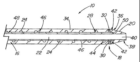
With respect to FIG. 2, shown is a sectioned view of the body 16.
Disposed underneath the body 16 is a reinforcement layer 24, which itself has
a
reinforcement proximal end 26 and a reinforcement distal end 28. Reinforcement
layer 24 generally is disposed under the body 16 and in some embodiments, the
reinforcement layer 24 can be shorter than the body 16, that is, reinforcement
layer
24 can terminate proximal to the distal end of the body 16. A radiopaque
marker
30 can be located generally at the reinforcement distal end 28, the distal end
of the
body 16, or at the distal tip 20. Radiopaque marker 30 comprises a material
sufficient to render the distal end 18 radiographically visible during the
medical
procedures. For example, the body, catheter, tip, or reinforcement layer can
be
made entirely or partially radiopaque. The radiopaque marker 30 can comprise a
dense material such as tantalum, bismuth, barium, tungsten, or some
combination
thereof. Preferably, the radiopaque marker 30 is 80 percent tungsten and 20
percent nylon. Radiopaque marker 30 can be disposed over the reinforcement
layer
24 such that the radiopaque marker 30 terminates proximate with the end of
reinforcement distal end 28. However, marker 30 can be disposed anywhere along
the device.
The reinforcement layer 24 provides structural integrity, strength, and
promotes torqueability and minimizes the kinking of the guiding catheter 10.
In this
manner, the reinforcement layer 24 permits a stronger material to be used
without
significantly increasing the outer diameter of the body 16. The reinforcement
layer
CA 02348523 2001-04-26
WO 00/35527 -~- PCT/US99/29962
24 can comprise stainless steel, KEVLAR , or other stronger material shaped
into
various configurations. Preferably, reinforcement layer 24 comprises stainless
steel,
such as but not limited to, being in the configuration of a braid 32. When
using
stainless steel as a braid 32, the tendency of the braid 32 to unwind
increases due
to the high tensile forces and thus braid 32 can be annealed in the
reinforcement
distal end 28 to form an annealed braid distal end 34. The braid 32 can be
annealed
using heat, which softens the metal and prevents the braid distal end 34 from
flaring
out after it is cut to shape. The annealing of braid 32 also prevents the
braid 32
from unraveling and having rough edges at the braid distal end 34 that might
puncture the body 16 and cause trauma to the vessel or cavity wall.
Preferably, the
braid distal end 34 is annealed for 1-5 cm and more preferably is annealed to
a
length of 1-3 cm. Preferably, braid distal end 34 terminates coincident with
the
radiopaque marker 30.
With reference to FIG. 3, shown is the distal end 18 of guiding catheter
10. In one embodiment of the present invention, radiopaque marker 30 and braid
32 terminate coincident with each other. Distal tip 20 comprises a tip
proximal
portion 36, a tip distal portion 38, and a tip lumen 40. The distal tip 20 and
radiopaque marker 30 junction creates a distal tip-radiopaque marker interface
42,
which demonstrates where the distal tip 20 joins the most distal part of body
16 and
generally where the tip 20 begins to taper. Distal tip lumen 40 communicates
with
guiding catheter lumen 22 such that it provides a relatively smooth transition
therebetween. Distal tip 20 can also be made of a radiopaque material to
increase
visualization.
Reinforcement layer 24 also includes a most distal end 44, which marks
the termination of the reinforcement layer 24. As shown in FIG. 3,
reinforcement
layer 24 can extend to the interface 42. However, in other embodiments, the
most
distal end 44 can terminate before the interface 42. Reinforcement layer 24 is
disposed over an inner tubular layer 46, which includes an inner tubular
proximal end
48 and an inner tubular distal end 50. Inner tubular layer 46 has a lumen 22.
As
shown in FIG. 3, inner tubular distal end 50 extends into the tip proximal
portion 36.
Preferably, inner tubular layer 46 can extend for a length of 1-2 mm into the
tip
12-01-2001 ~ 02348523 2001-04-26 US 009929962
2 PCT REPLACf~T (
- $ - j'fnatio
n C py
proximal portion 36, however it can extend more into the tip proximal portion
36 as
desired. Similarly, reinforcement layer 24 can extend for some distance into
the
proximal portion of the tip. Depending on the length of distal tip 20, the
most distal
end 44 of reinforcement layer 24 can also extend into the tip proximal portion
36.
Preferably, the guiding catheter 10 is so constructed that the most distal end
44
terminates within 9 mm proximal to the inner tubular distal end 50. More
preferred
is that the most distal end 44 terminate within 5 mm of the inner tubular
distal end
50 and most preferred is where the most distal end 44 terminates within 1 mm
proximal to the inner tubular distal end 50. In one particular embodiment, as
shown
in FIG. 3, inner tubular distal end 50 extends only 1-2 mm into the tip
proximal
portion 36, thereby having the most distal end 44 of the reinforcement layer
24
terminate near the interface 42 and coincident with radiopaque marker 30.
Thereby,
reinforcement layer 24 is further secured in that radiopaque marker 30 sits
atop
reinforcement layer 24 and ensures that reinforcement layer 24 does not
unravel or
have protruding edges. Reinforcement layer 24 and most distal end 44 can
terminate within 9 mm proximal of the interface 42, preferably within 5 mm
proximal
of the interface 42, and most preferably within 1 mm proximal thereof.
Inner tubular layer 46 comprises a biocompatible material that is strong
enough to withstand the delivery of an instrument within the inner tubular
layer
lumen 22. For example, the inner tubular layer 46 can comprise a fluorocarbon,
polyamide, polyolefin, polyimide, or some combination thereof. Preferably,
inner
tubular layer 46 comprises polytetrafluoroethylene.
In construction of the guiding catheter 10, the reinforcement layer 24 is
disposed over the inner tubular layer 46. The body 16 is wrapped around the
reinforcement layer 24 - inner tubular layer 46 construct to form the guiding
catheter
10. As is seen in FIG. 3, the distal end of body 16 is recessed proximally
from the
distal end 50 of inner tubular layer 46 for a small distance. The distal tip
20 is slid
adjacent to the body 16 by sliding it over the distal portion of the inner
tubular layer
46 as shown in FIGS. 1, 2 and 3. The distal tip 20 can be provided with a tip
recess
to accommodate the inner tubular layer 46 or reinforcement layer, or both, to
facilitate the construction. Shrink wrapping is done by wrapping the body 16
and
distal tip 20. The shrink wrapped guiding catheter 10 is then heated to melt
the
body 16, which generally comprises nylon
AMENDED SHEET
CA 02348523 2001-04-26
1 2-01-2001 2 PCT REPLA(~6)~NT I US 009929962
,~'/
-9- CpAy
tubing, so the body 16 material flows down through the lacunae of the braid 32
and
mechanically bonds to the inner tubular layer 46 after the nylon cools. In
addition,
by selecting the materials desired, the radiopaque marker 30 and distal tip 20
can
also melt in such a manner that the material of the distal tip 20 bonds to the
inner
tubular layer 46 below it and bonds to the radiopaque marker 30 adjacent to
it. The
shrink wrap is removed and the distal tip 20 is reheated over a mandrel
projecting
into the tip lumen 40 such that the distal tip 20 can be extended to a desired
length
and diameter. The distal tip 20 can also be shaped into various
configurations.
Thus, the shrink wrapping and heating process permits the body 16 to melt
sufficiently to provide additional insurance that the reinforcement layer 24
will not
easily unravel and ensures that the distal tip 20 will not dislodge or detach
since the
distal tip 20 is bonded to the underlying inner tubular layer 46 and to either
the body
16 itself or the radiopaque marker 30, or both.
With reference to FIG. 4, inner tubular layer 46 can comprise a material
that facilitates easy movement of a medical device within the lumen. In
another
embodiment of the present invention, the proximal end 14 of the guiding
catheter
10 can be made to maximize the tension of the inner tubular layer 46 to
prevent
sagging or catching. As described above, inner tubular layer 46 can comprise a
TEFLONO material. As such, devices inserted into the lumen 22 can catch,
scrape,
or tear at the inner tubular layer 46. Therefore, tightening the inner tubular
layer 46
up against the reinforcement layer 24 and the body 16 minimizes this problem.
Like
any material, stretching it makes it less likely to sag and reduces the
likelihood of
something else catching on it. Body 16 has a proximal portion 14 where the
inner
tubular layer 46 inserts into the handling portion 12. By folding the body 16
proximal end 48 inside out over the body 16 to form a cuff 52, the inner
tubular
layer 46 forms the cuff outside surface 54 of the cuff 52. The cuff inner
surface 56
of the cuff 52 is disposed a distance along the radially outwardly facing
outside
surface 58 of the body 16.
With reference to FIG. 5, shown is a section of the proximal portion 14
of the guiding catheter tube cut along its longitudinal axis and unfoided into
a
flattened multilayered structure. FIG. 5 demonstrates one aspect of cuff 52
formation having a cuff edge 60 that is the end most portion of the cuff 52.
Body
AMENDED SHEET
CA 02348523 2001-04-26
WO 00/35527 _ 1 0- PCT/US99/29962
16 has an outside surface 58. Although shown in FIG. 5, it is not necessary
that
reinforcement layer 24 terminate coincident with the body 16 or inner tubular
layer
46 in the cuff 52, as the reinforcement layer 24 can terminate in the proximal
portion 14 before the cuff 52 begins. Similarly, it is not necessary that the
body 16
and inner tubular layer 46 terminate coincident at the cuff edge 60. As shown
in
FIG. 6, by having the relatively thicker body 16 or reinforcement layer 24
terminate
before, or taper as they enter the cuff 52, the amount of material folded over
into
the cuff 52 is significantly reduced. As such, the cuff edge 60 will comprise
a
relatively thin layer of the inner tubular layer 46, of body 16, or
reinforcement layer
24; or some combination thereof. Various embodiments are shown in FIGS. 6 and
7.
With respect to FIGS. 6 and 7, shown are various embodiments of the
proximal portion 14 and cuff 52 demonstrating the various termination points
of the
reinforcement layer 24 and body 16. With respect to reinforcement layer 24,
reinforcement layer 24 can terminate abruptly forming a reinforcement layer
abrupt
end 62, or taper such that it terminates prior to the cuff 52 and prior to
cuff junction
64, which is the junction at which the cuff 52 begins to turn outward.
Illustratively
shown in FIG. 7, reinforcement layer 24 can terminate in a reinforcement layer
medium taper 66, which terminates prior to the cuff junction 64, or can
terminate
in a reinforcement layer long taper 68, which terminates at the cuff junction
64.
Reinforcement layer 24 can terminate in the cuff as it can terminate after the
cuff
junction 64.
Again with respect to FIG. 7, body 16 can terminate prior to, at, or after
cuff junction 64. Illustratively shown, body 16 can terminate in a body abrupt
end
70, in a body medium taper 72, which terminates prior to the cuff edge 60, or
can
terminate in a body long taper 74, which terminates coincident with cuff edge
60.
In this manner, the inner tubular layer 46 is pulled tightly against the
reinforcement layer 24 and the body 16 due to the cuff 52 formation. The
amount
of material forming cuff 52 is significantly reduced if reinforcement layer 24
and
body 16 taper prior to, or coincident with the cuff junction 64.
CA 02348523 2001-04-26
WO 00/35527 PCTIUS99/29962
In yet another embodiment of the present invention, the reinforcement
layer 24 and body 16 can be disposed over the inner tubular layer 46. In
addition
to the cuff 52 providing a snug, non-snagging surface, the inner tubular layer
46
could be further affixed to the reinforcement layer 24. Such means for
affixing the
inner tubular layer 46 to the reinforcement layer 24 or body 16, include but
is not
limited to, bonding, adhesion, mechanical attachment, heat sealing,
compression, or
other well-known ways to adhere one layer to another.
It is understood that the above described guiding catheter is merely an
illustrative embodiment of the principles of the disclosed invention. As such,
other
embodiments of the invention are contemplated as identified and protected
within
the appended claims.