Note: Descriptions are shown in the official language in which they were submitted.
CA 02348682 2001-06-07
BACKGROUND OF THE INVENTION
1. FIELD OF THE INVENTION
The present invention relates to log construction.
2. DESCRIPTION OF THE RELATED ART
Despite the advances in modern building construction techniques, the
traditional log
construction nonetheless remains popular, due to its aesthetic traditional
appearance.
Modern log buildings are commonly made in a prefabricated fashion at a factory
site, and then
delivered to the destination.
The most dominant disadvantage to log construction is that the log walls tend
to be
drafty, particularly due to long term shrinkage and settling, which exposes
gaps between the
log joints. As the shrinkage occurs, the log construction tends to lose some
structural
integrity due to loosening joints. Advances in packing materials have made
significant
advances in reducing air infiltration through the log wall, but problems still
remain.
It is an object of the present invention to provide an improved log
construction
techniques.
SUMMARY OF THE INVENTION
Briefly stated, the present invention involves a log construction comprising a
pair of
logs, each being formed with two upright boundary surfaces, each boundary
surface of one
log being complementary to the corresponding upright boundary surface of the
other log
when arranged in a corner formation therewith, each of the logs having a pair
of cavities,
each of the cavities extending along and open to an entire vertical dimension
of a respective
CA 02348682 2001-06-07
boundary surface, so that, in the corner formation, the opposing cavities in
each mating pair
of boundary surfaces form a passage, and a resilient material sufficiently
located in each of
the passages to form a barrier to weather across the boundary surfaces.
Preferably, the corner formation is a dove tail configuration, although other
configurations are also contemplated such as rectangular notched corners.
Preferably, each of the boundary surfaces terminate partway through the log
and the
cavities are formed by cut outs extending the full thickness of each of the
logs.
Desirably, the resilient material is in the form of a blank which, in one
embodiment,
is positioned to extend the full length of the boundary surface and partway
into the cut out.
The blank and the passages are preferably of generally circular cross section,
although other
cross sectional shapes are also contemplated. The blank may be an open cell or
closed cell
plastics material, such as polyethylene, neoprene, or polypropylene material.
In another of its aspects, the present invention provides a log construction
comprising:
a pair of logs, each having an end region with a surface portion thereon,
wherein the
surface portions are arranged to engage one another at a boundary there
between, the
boundary having a length,
at least one barrier extending across the boundary and along the length
thereof to
couple the end regions together, the barrier having a pair of projections,
each of the logs further comprising a passage open to and adjacent the
boundary for
receiving a corresponding one of the projections,
each of the projections having a pair of outer surfaces and the passage having
a pair
2
CA 02348682 2001-06-07
of inner surfaces, the outer and inner surfaces being further arranged to
generate residual
compressive forces toward the boundary as a result of shrinkage between the
barrier and the
end regions.
In another aspect of the present invention, there is provided a method of
forming a log
construction comprising the steps of:
providing a pair of logs, each with an end region having a surface portion
thereon,
arranging the surface portions are arranged to engage one another at a
boundary there
between, the boundary having a length,
providing at least one barrier to extending across the boundary and along the
length
thereof to couple the end regions together, the barrier having a pair of
projections,
forming in each of the logs a passage open to and adjacent the boundary for
receiving
a corresponding one of the projections,
forming on each of the projections a pair of outer surfaces and in the passage
a pair
of inner surfaces,
arranging the outer and inner surfaces to generate residual compressive forces
toward
the boundary as a result of shrinkage between the barrier and the end regions.
BRIEF DESCRIPTION OF THE DRAWINGS
Several preferred embodiments ofthe present invention will now be described,
by way
of example only, with reference to the appended drawings in which:
3
CA 02348682 2001-06-07
Figure 1 is a perspective assembly view of a log construction;
Figure 2 is a fragmentary plan view of the log construction of figure 1;
Figure 3 is a magnified fragmentary perspective assembly view of one portion
of the
log construction of figure 1;
Figure 4 is a magnified fragmentary plan view of a portion of the log
construction of
figure 1;
Figure 4a and 4b are magnified fragmentary plan views of other log
constructions;
Figure 5 is a magnified fragmentary schematic plan view of the log
construction of
figure 4;
Figure 6 is a magnified fragmentary schematic plan view of another log
construction;
Figure 7 is a fragmentary assembly view of still another log construction;
Figure 8 is a fragmentary perspective view of yet another log construction;
Figure 9 is a fragmentary plan view of yet another log construction;
Figure 10 is a sectional view taken on line 10-10 of figure 9;
Figure 11 is a fragmentary assembly side view of yet another log construction;
Figure 12 is a fragmentary sectional view taken on line 12-12 of figure 11;
4
CA 02348682 2001-06-07
Figure 13 is a sectional view of yet another log construction;
Figure 14 is a fragmentary plan view of the log construction of figure 13;
Figure 15 is a schematic representation of alternative portions of the log
construction
shown in figure 13;
Figure 16 is a fragmentary perspective view of the log construction of figure
13; and
Figure 17 is a fragmentary perspective view of still another log construction.
DESCRIPTION OF THE PREFERRED EMBODIMENTS
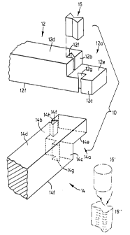
Referring to the figures, there is provided a log construction 10 comprising a
pair of
logs 12, 14, each log having an end region 12a, 14a formed to engage one
another, for
example by a rectangular joint. The logs have adjacent first surface portions
12b, 14b and
adjacent second surface portions 12c, 14c, each with a length'W' between an
outer surface
12d, 14d and an intermediate surface 12e, 14e. As seen in figure 2, the
surface portions are,
when assembled, separated by a boundary 15, and are preferably upright and
planar. In this
case, the boundary is shown to involve a large gap for illustrative purposes
only.
The end regions further comprise first barrier receiving passages 12f, 14f
adjacent the
first surface portions and second barrier receiving passages 12g, 14g which
are open to and
adjacent the second surface portions and the boundary in their assembled
condition.
A rigid barrier, in the form of a key 16, is provided to engage each pair of
aligned
passages 12f, 14f and 12g, 14g, to interrupt the boundary between the adjacent
surface
portions along substantially the entire length thereof, thereby to couple the
end regions
together.
5
CA 02348682 2001-06-07
Preferably, the key has a tensile strength, shear strength and a stiffness to
inhibit
bending and stretching relative to the central axis shown at'A'. Once
assembled, the key also
has the capacity to inhibit displacement of one surface portion relative to
its adjacent surface
portion, thereby inhibiting relative movement of the logs, that is to inhibit
displacement of one
surface portion relative to another transverse to the boundary. The degree to
which the key
will inhibit such relative movement depends on the fit between the key and the
aligned
passages.
Each of the key receiving passages includes a bearing surface 12h, 14h, to
establish
a loaded condition with the barrier. In this manner, each of the bearing
surfaces of one
passage, has a corresponding opposed bearing surface in the other barrier
receiving passage.
This can be seen in figure 4 wherein the bearing surfaces 12h in log 12 are
aligned with the
opposed passages 14h in log 14.
The outer surfaces of the projections and the corresponding inner surfaces of
the
passages are complementary and are further arranged to generate residual
compressive forces
toward the boundary as a result of shrinkage between the barrier and the end
regions, thereby
to establish this compressive loading. Further, the keys and their
corresponding passages may
be configured to establish tensile loading on the key and consequently
compressive loading
on the bearing surfaces in order to have the effect of drawing the logs
together, that is to
minimize the spacing between the surface portions at the boundary 15.
Therefore, the tensile
strength and stiffness should be sufficient to withstand these forces.
The key 16 has a pair of aligned webs 16a, 16b, each shaped to fit snugly
within a
corresponding one of the barrier receiving passages (though a loose fitting is
shown for
illustrative purposes). The webs 16a, 16b are also joined by a central portion
16c to extend
across the boundary 15. Each of the projections includes a pair of bearing
surface portions
16d, 16e for engaging a corresponding bearing surface in the barrier receiving
passage.
6
CA 02348682 2001-06-07
Preferably, the projections are symmetrically arranged along the common
central axis
'A'. The outer surfaces of each of the projections diverge from the boundary
relative to the
axis. More preferably, the projections are triangular in cross section, for
example 'wedge
shaped'. In another embodiment, as shown in figure 4a, the central portion has
parallel
opposing side faces 17a and the outer corners are rounded as shown at 17b,
17c. In still
another embodiment, the projection has circular divergent outer surfaces 19a,
19b as shown
in figure 4b. The log construction can also utilize a number of known log
joinery techniques,
such as a dove tail joint as shown in figure 7, which also makes use of a
central portion with
parallel opposing side faces as shown at 21.
A particular feature of the log construction is that the barrier and the logs
may be
formed from materials with different "coefficients of shrinkage", a term which
is intended to
refer to the degree to which a particular material shrinks over a
predetermined period of time
and may be expressed by some ratio of the 'pre-shrink' length and the 'post-
shrunk' length of
a unit sample of the material. For example, green softwood such as pine or
spruce should
shrink to a greater extent (and therefore have a correspondingly higher
coefficient of
shrinkage) than a green hardwood, and to a much greater extent than a
substantially cured
hardwood, as one might obtain after an appropriate period of kiln or air
drying, for example.
Preferably, the barrier and the logs are both formed from wood materials,
while the
barrier is formed from material with a lower shrinkage coefficient than the
material of the
logs. Still more preferably, the barrier is formed from hardwood materials and
the
logs are formed from softwood materials. More particularly, the barrier is
formed from a
single piece of substantially cured hardwood and the softwood material is
green.
Conveniently, the barrier and the passages are dimensioned so that the barrier
can be
installed in place by slidably engaging the barrier with the passages during
assembly.
7
CA 02348682 2001-06-07
Surprisingly, the compressive forces arising between the barrier and its
associated end
region from the natural effects of shrinkage may be directed to draw the end
regions so
coupled into tighter engagement without the need for additional locking or
wedging
hardware. As can be seen in figure 5, the green softwood of the end region
tends to shrink
over time, thereby making the passage smaller in cross sectional area shown by
the chain
dotted lines, that is it has a relatively high coefficient of shrinkage.
Because the barrier itself,
in this particular example, is made from a substantially cured hardwood, it
should not shrink
to any measurable degree and therefore has a significantly smaller coefficient
of shrinkage.
The barrier, as a result, will become more tightly engaged within the passage
as it reduces in
size, thereby causing, in effect, a squeezing action on the barrier.
A particular aspect here is the arrangement of the inner and outer surfaces
which,
though symmetrical relative to the common central axis'A', the surfaces are
not symmetrical
about a central transverse axis shown'B', as might otherwise occur if the
cross section of the
projection were, for example symmetrically circular or ellipsoid in cross
section, as shown in
figure 6. In other words, the compressive forces exerted on a circular
projection by its
con esponding passage on one side of the transverse axis, would balance
themselves off with
the forces on the opposite side of the transverse axis, resulting in
substantially no residual
forces emerging therefrom.
In the case of the embodiment of figure S, the compressive forces F~ on one
side of
the transverse axis do not balance those on the other side and in fact they
reinforce one
another and this resulting residual force is directed toward the boundary and
has the effect of
drawing both end regions inwardly toward one another at the boundary. This
residual force
is generated between the surfaces which are arranged in a divergent manner
away from the
opening to the boundary, and in the case of the triangular cross section, have
no
corresponding convergent surfaces that would otherwise balance to create a
substantially zero
residual force relative to the common central axis. Thus, the outer surfaces
are
asymmetrically arranged relative to the transverse axis. The residual forces
therefore are
8
CA 02348682 2001-06-07
caused by the compressive forces F~ generated at the intersection of the inner
and outer
surfaces and more particularly to the component thereof in the direction of
the common
central axis, as shown at F~ and F~. In other words, the force F,~ tends to
force the end
region toward the boundary while the force FRK tends to force the key away
from the
boundary, the net effect being biasing of the end regions together to minimize
the spacing
there between at the boundary and to form a snug connection there between. In
order to
provide these compressive forces, the angle of the inner surface of the
passages may be at an
angle 8 ranging from 45 to 85 degrees and more preferably about 80 degrees.
It will be understood, that the surfaces may come in any number of different
configurations, provided that they arranged in a similar manner as above.
The joining technique shown herein above is particularly useful because it is
simple
to install and requires no additional tightening manoeuvres with additional
wedging devices.
Rather, the present technique makes use of the natural compressive forces
caused by the
natural shrinkage of the materials. The same technique can be used to form
butt joints and
corner joints in the same log construction thereby reducing the number of
parts necessary for
a particular construction.
The length of the keys depends on the length'W', which of course will depend
on the
thickness of the logs and the profile of the particular joint pattern used,
the intention being
that the key extends the entire length'W'. By extending the entire length, the
key can provide
an effective barrier against the infiltration of air through the log wall as
would otherwise
occur through the boundary as shown by the arrows in figure 3.
However, the entire length may also be spanned by more than one single
barrier. The
single barrier may be replaced with, for example, three keys, all with a
collective length
equaling that of the single key as shown at 21a, b, c in figure 7.
9
CA 02348682 2001-06-07
The log construction may be formed in the following manner. First, the logs
12, 14
are cut to length and their end regions are shaped so as to engage in a
complementary fashion
as shown above. The barrier receiving passages 12f, 14f, 12g, 14g are formed
so that they
extend from the outer surface 12d, 14d to the intermediate surface 12e, 14e.
The keys are
then formed with a cross section which is complementary to that of the aligned
passages.
The keys may be slightly undersized in the direction of the axis 'A' in order
to
immediately establish a loaded condition with the bearing surfaces. With the
logs in their
position with the passages aligned, the keys may then be pressed in place with
appropriate
caulking compounds placed therein as necessary. The joint may then be left to
the forces of
nature to bring about the shrinkage of the materials to establish the residual
forces as
described.
The cross sections used herein have the additional benefit of increasing the
engaged
surface area of the inner and outer surfaces, both to increase the area which
is available for
caulking materials, if desired, or to otherwise increase the distance that
infiltrating air would
need to travel to circumvent the barrier so formed.
The key may, if desired, by dimensioned to extend beyond a single joint. For
example,
the keys may extend beyond two or more joints as shown in the log construction
30 shown
in figure 8. In this case, there are provided two sets of logs 32, 34, with
each set having a
number of aligned end regions 32a, 34a, with each log element from set 32
formed to engage
a pair of adjacent logs in set 34. There is provided a series of first surface
portions as shown
at 32b, and a series of second surface portions as shown at 32c.
In this case, each log is also provided with barrier receiving passages 33a,
33b, each of
which extends the full thickness of the log so that, when assembled as shown
in figure 8, the
passages 33a, 33b align together to form a substantially continuous elongate
passage
extending the full length ofthe so-formed log'wall'. This is shown in the case
ofthe passages
CA 02348682 2001-06-07
33a by the dashed lines at "33A".
A pair of keys 36, 38 engage the elongate passage 33a, 33b, thereby to
interrupt the
boundary between the adjacent surface portions and to inhibit relative
movement between the
log elements of each set of logs in the construction.
The keys used herein may be formed from a number of materials. Hardwood
materials
such as maple and oak are readily available and provide a natural counterpart
to the soft
woods normally used for the logs themselves.
However, other materials such as plastics are also envisioned. In this case,
the
materials may be preformed into the keys as shown above or alternatively be
arranged to be
forced in a liquid or other deformable consistency, into the aligned passages.
This technique
has the advantage that the key forming material can fill the voids in the
aligned passage, while
accommodating minor misalignments between the logs. Furthermore, the passages
can be
finished in such a manner to allow the key forming material to partially or
fully extend beyond
the passages themselves and fill the spacing the between the adjacent surface
portions. The
key forming material, in this case, may be a thermoset material such as those
defined as
epoxies or thermoplastics such as polyethylene or polypropylene. The
characteristics of the
formed key may also be modified by adjusting the make up of the material, for
example by
adding a reinforcing fibre and the like.
Referring to figure 9, there is provided another log construction SO with a
pair of logs
52, 54 having complementary end regions 52a, 54a. In this case, the
complementary end
regions are simply a flat end face to form a butt joint having a transverse
boundary 56. A
barrier in the form of a key 58 is arranged in a like fashion to that shown
above to interrupt
the boundary along substantially the entire transverse dimension thereof, in
this case, the
height as shown in figure 10.
11
CA 02348682 2001-06-07
Referring to figures 11 and 12, there is provided still another log
construction 70 with
a pair of logs 72, 74 having complementary end regions 72a, 74a. In this case,
the
complementary end regions are simply a flat end face to form a butt joint
having a transverse
boundary 76. One end face has a projection 74b and the other end face has a
complementary
S recess 72b. A pair of fastening assemblies 78 are provided to engage each of
the end regions
on opposite sides thereof. Each of the fastening assemblies includes a pair of
cylindrical plugs
80 mounted on a base plate 82, each plug adapted to receive a fastener such as
a spike 84,
by way of a small elongate passage or the like. A pair of passages extend
through each of the
end regions 72a, 74a and are dimensioned so as to receive a corresponding pair
of plugs as
shown.
The spikes are dimensioned to that they can be driven through the upper plug
and
project into the lower plug thereby to hold the fastening assemblies in place.
The plugs are
firmly mounted on the plate so that the plate can absorb the loading exerted
thereon should
1 S the butt end joint. If desired, the plugs may be dimensioned to extend
fully into the passages
and abut one another as shown in dashed lines in figure 12.
Referring to figures 13 and 14, there is provided still another log
construction 100,
in the form of a butt joint, with a pair of upper logs 102, 104 and a lower
log shown at 106
having end regions 102a, 104a, each being a flat end face to form a butt joint
having a
transverse boundary 110. Each log has an upper face 102b, 104b with a pair of
tongues 102c,
104c which are collinear with one another when assembled into the butt joint
as shown in
figure 14. Each end face has a pair of recesses 102d, 104d, which are aligned
with a
corresponding tongue 102c, so that the recesses are also aligned when the butt
joint is
formed, again as shown in figure 14. Extending through each of the aligned
pair of recesses
is a spline shown at 112, which is preferably a hardwood material. The spline
has a
rectangular cross section but may be provided with other cross sections, such
as those in
earlier embodiments herein.
12
CA 02348682 2001-06-07
Referring to figure 13, each log has a pair of grooves, shown at 102e for log
102.
Each groove is shaped to be complementary with the tongue 106c of the lower
log I 06. The
tongue 106b is further provided with an edge region 106f which is oriented to
the exterior of
the wall being formed by the logs. The spline 112 has a lower surface 112a
which is
complementary with the shape of the groove 102e. The spline is also shaped to
have an
overlying portion 112b which overlies the outer edge region 106, for reasons
to be described.
The spline 112 also has an upper edge region I 12c which terminates below the
height of the
tongue 102c and has a pair of beveled edges shown at 112d.
The central region of each log has a groove in its upper face and a tongue in
its lower
face, such as shown at 102g and 102h respectively for log 102. Again, the
central grooves
and tongues of logs 102, 104 are aligned when in the butt joint. AS shown in
figure 12, a
plate 116, preferably with width approximately equal to the width of the
central grooves, is
located therein and is provided as pair of passages 116a. Each passage 116a
receives a screw
118 which extends into the respective log, through the gap between the
respective upper log
and the lower log 106 to be anchored therein, thereby drawing the upper and
lower logs
together. The groove 1028 is further provided with a recess 102h to receive
the plate 116
so that its upper face is substantially flush with the inner surface of the
groove.
A number of seals are provided at locations throughout the butt joint, namely
a pair
of seals between the tongues and grooves between the upper logs and the lower
log 106 (as
shown at 120a, 120b), a central lower seal between the central tongues of the
upper logs and
the central groove on the lower log 106 (as shown at 120c), a pair of spline
seals positioned
in the gap between the upper region of the spline and the tongue 102a (as
shown at 120d,
I 20e) and a seal positioned in the central groove and above the plate I 16.
In the case of the
spline seal 120d, the lateral edges of the seal are squeezed over the beveled
edges 112d of the
spline.
To assemble the butt joint, the logs are assembled as shown with the splines
inserted
13
CA 02348682 2001-06-07
in their respective recesses and the seals positioned between the logs 102,
104 and the lower
log 106, namely seals 120a, 120b and 120c. The plate 116 is then installed in
its recess 102h
and the screws 118 driven through in their corresponding passages 116a.
Finally, the seals
120d, 120e and 120f are installed.
When the log wall is completed, the overlying portions 112b of the splines
assist the
seals in providing an effective barrier against the infiltration of air
through the log wall, that
is between the tones and the grooves. Over time, the shrinkage of the logs
will cause the
tongue 102c to be reduced toward the level of the spline I 12. Thus, by
providing the gap
between the upper edge region of the spline and its associated tongue, the
joint will become
tighter over time, while the seals I 20d, 120e will accommodate the gap in the
meantime and
reduce infiltration.
If desired, the overlying portions may be placed on opposite outer edge
regions as
shown in version 'B' of figure 1 S. Alternatively, the overlying portions may
be provided on
both sides of each spline as shown in version'C' of figure 15.
In another embodiment, a corner joint is formed in a similar manner to that
shown in
figure 1, except that the key I 6 is not formed of hardwood materials but
rather is formed from
a foam material such as a closed cell polyurethane material, such as a
preformed compressible
blank of such material. In this embodiment, cross sectional shape of the
passage receiving the
key is not necessarily as that shown above but is simply selected to
relatively tightly receive
the foam material blank, by compressibly sliding the blank into the associated
aligned
passages. It is desirable that the blank be, in its natural state, bulkier
than the passage in order
to enhance its sealing qualities when inserted in the passage, as shown at
16', 16" in figure 1.
Referring to figure 17, still another log construction is shown at 130 having
a pair of
logs 132, 134, each of which is formed with two upright boundary surfaces
132a, 134a, 132b,
134b. Each boundary surface 132a, 134a is complementary to the corresponding
upright
14
CA 02348682 2001-06-07
boundary surface 134a, 134b when the logs are arranged in a corner formation
therewith.
In this case, the upright boundary surfaces are complementary by being
generally vertical in
orientation. Log 132 has a pair of cavities 132c, 132d and log 134 has a
corresponding pair
of cavities 134c, 134d. Each of the cavities extend along and are open to an
entire vertical
dimension of a respective boundary surface, so that, in the corner formation,
the opposing
cavities in each mating pair of boundary surfaces form a passage, and a
resilient material
sufficiently located in each of the passages to form a barrier to weather
across the boundary
surfaces.
Each of the boundary surfaces 132a, and 134b can be considered inner boundary
surfaces because they terminate partway through the log. In this case, the
cavities 132c and
I 34d are formed by cut outs 1328, 134g extending the full thickness of each
of the logs. In
this case, the cutouts are circular but can be of some other configuration.
Preferably, the corner formation is a dove tail configuration such as the type
shown
in figure 7, although other configurations are also contemplated such as
rectangular corners,
as shown in figure 17.
Desirably, the resilient material is in the form of a blank 136 which, in one
embodiment, is positioned to extend the full length of the boundary surface
and partway into
the cut out. The blank and the passages are preferably of generally circular
cross section,
although other cross sectional shapes are also contemplated. The blank may be
an open cell
or closed cell plastics material, such as polyethylene, neoprene, or
polypropylene material.
For example, the aquatic floatation product sold widely in Canada under the
trade name
NOODLE can be used as the blank, if desired, when cut to the desired length to
extend the
entire length of each of the passages.
The log construction of figure 17 can be assembled as follows. First, the logs
are
formed with their complementary end regions, that is to form a suitable corner
joint. Then,
CA 02348682 2001-06-07
the cavities are formed in each of the corresponding boundary surfaces, for
example by boring
a hole through the log, in the case of passages 132c and 134d, wherein the
corresponding
cavity emerges in the region of the boundary surface. The cavities 132d, 134c
are also
formed, in this case also extending through the entire length of the
corresponding boundary
surfaces. The so-formed resulting cavities are generally concave and of a
generally
semicircular shape in this particular example, though the cavities may be in
some other
curvilinear or angular shape as desired. Two blanks 136 are then formed for
each corner as
shown herein, that is for the intersection of two logs. Being slightly larger
to enhance their
sealing effect with the sides ofthe cavities, the blanks 136 are slightly
compressed while being
pressed into placed. A log wall can be similarly formed by adding logs to the
corner as
needed.
16