Note: Descriptions are shown in the official language in which they were submitted.
CA 02348729 2001-06-05
COMBUSTION BOILER
BACKGROUND OF THE DEVICE
I . Field of the Device
The present device relates to a combustion boiler, and relates more
particularly
to a combustion boiler that can have improved air suction and exhaust
functions.
2. Description of the Related,An
As well known, boiler:> are divided into various kinds in accordance with heat
source kinds, installation manners, places to be installed, suction and
exhaust manners,
feed water methods, structures of a heat exchanger and so on.
FIG. 1 shows an exemplary view of a conventionally used upward
combustion boiler with an exhaust fan part. As shown, the conventional upward
combustion boiler uses a heating pin 93a, wherein air is sucked from the
outside, while
an exhaust gas is being forcedly exhausted to the outside by virtue of an
exhaust fan
part 20.
In operation, if a driving motor 21 of the exhaust fan part 20 operates, an
exhaust fan 23, which is fixed on the rotary shaft of the driving motor 21 is
rotated,
with a result that the air within a combustion chamber A forcedly flows to an
exhaust
line 60. Therefore, the intet~nal pressure of the exhaust line 60 is higher
than an
atmospheric pressure, whereas a back pressure thereto is applied to the
combustion
chamber A, a burner 30, a suction line 13 and a suction inducing member 11,
such that
the air from the outside is sucked to the suction inducing member 11 through
inlet
holes l la and then flows to the combustion chamber A via the suction line 13
and the
burner 30. After that, the air forcedly flows to the exhaust line 60 through
the exhaust
CA 02348729 2001-06-05
fan 23 and is finally exhausted to the outside via outlet holes 50a of the
exhaust line 60.
Under the above state, when fuel is injected from a fuel supply line 70 via a
nozzle 80a of a fuel injection part 80, the fuel injected is mixed with the
air in the
interior of the burner 30. Then, the resulting mixed gas is emitted to the
combustion
chamber A via flame holes of tlhe burner 30.
At this time, if an igniter (which is not shown in the drawing) operates, the
mixed gas emitted through the flame holes of the burner 30 is ignited.
On the other hand, when heating water in a heating line is forcedly circulated
by means of a circulating pump 100, the heating water at a low temperature
flows from
the lower portion of a heater (which is not shown in the drawing) to a heat
exchanger
93 through a water inlet tube 91 and is then returned to the lower portion of
the heater
through a water outlet tube !~2. As a consequence, the heating water at the
low
temperature in the heat exchanger 93 with the heating pin 93a is heated to a
high
temperature by the combustion gas at a high temperature in the combustion
chamber A,
and the heating water at the low temperature from the water inlet tube 91
flows in the
interior of the heat exchanger 93 and heated to a high temperature. Then, the
heated
water is returned to the lower portion of the heater through the water outlet
tube 92.
FIG. :2 shows another exemplary view of a conventionally used upward
combustion boiler with an e;~chaust fan part. As shown, the conventional
upward
combustion boiler uses a combustion gas inducing tube 45, wherein air in the
room is
sucked, while an exhaust gas is being forcedly exhausted to the outside by
virtue of the
exhaust fan part 20.
In operation, if the driving motor 21 of the exhaust fan part 20 operates, the
exhaust fan 23, which is fixedl on the rotary shaft of the driving motor 21 is
rotated,
2
CA 02348729 2001-06-05
with a result that the air within an exhaust chamber SO forcedly flows to the
exhaust
line 60 (See FIG. 3) through an exhaust hole 20a of the exhaust fan part 20.
Therefore,
the internal pressure of the exhaust line 60 is higher than an atmospheric
pressure,
whereas a back pressure thereto is applied to the exhaust chamber 50, the
combustion
gas inducing tube 45, a combustion chamber 48, a suction chamber 14 and a
suction
line 13, such that the air in the room is sucked to the opening of the suction
line 13 and
then flows to the suction chamber 14 via the suction line 13. After that, the
part of the
air induced to the suction chamber 14 directly flows to the combustion chamber
48
through the hole of the suction chamber 14 and the other flows to the interior
of the
burner 30 through a Venturi tube 31 and then to the combustion chamber 48
through
the flame holes of the burner' 30. Thereafter, the air flown to the combustion
chamber
48 is delivered to the exhaust chamber 50 through the combustion gas inducing
tube
45 and then forcedly flows to the exhaust line 60 through the exhaust fan 23
rotating,
thereby being finally exhausted to the outside.
Under the above state, when fuel is injected from the fuel supply line 70 via
the nozzle 80a of the fuel injection part 80 to a Venturi tube 31 of the
burner 30, the
fuel injected is mixed with the air in the interior of the suction chamber 14.
Then, the
resulting mixed gas is emitted to the combustion chamber 48 via the flame
holes of the
burner 30.
At this time, if an igniter (which is not shown in the drawing] operates, the
mixed gas emitted through the flame holes of the burner 30 is ignited.
On the other hand, when heating water in a heating line is forcedly circulated
by the circulating pump 100 (See FIG. 1 ), the heating water at a low
temperature flows
from the lower portion of a heater (which is not shown in the drawing) to a
water
3
CA 02348729 2001-06-05
chamber 46 of a heat exchanger 40 through the water inlet tube 91 (See FIG. 1)
and is
then returned to the lower portion of the heater through the water outlet tube
92 (See
FIG. 1). As a consequence. floe heating water at the low temperature in the
water
chamber 46 of the heat exchanger 40 is heated to a high temperature by the
combustion gas being at a high temperature that flows in the combustion
chamber 48
and the combustion gas inducing tube 45 and then returned to the lower portion
of the
heater through the water outlet tube 92.
FIG. 3 shows still another exemplary view of a conventionally used upward
combustion boiler with an exhaust fan part. As shown, the conventional upward
combustion boiler uses a combustion gas inducing tube 45, wherein air is
sucked from
the outside, while an exhaust I;as is being forcedly exhausted to the outside
by virtue
of the exhaust fan part 20.
In this case, a suction inducing member 11 is disposed on the free end portion
of the exhaust line 60, outlet holes 60a and inlet holes 11 a are respectively
provided on
the free end of the exhaust line 60 and on the front end of the outside of the
suction
inducing member 11, and the suction line 13 communicates with the suction
inducing
member 11, such that the exhaust gas is exhausted to the outside, while the
air in the
outside is being sucked.
FIG. 4 shows an exemplary view of a conventionally used downward
combustion boiler with an e:Khaust fan part. .As shown, the conventional
upward
combustion boiler uses a combustion gas inducing tube 45, wherein air in the
room is
sucked, while an exhaust gas i<.> being forcedly exhausted to the outside by
virtue of the
exhaust fan part 20.
In operation, if the driving motor 21 of the exhaust fan part 20 operates, the
4
CA 02348729 2001-06-05
exhaust fan 23, which is fixed on the rotary shaft of the driving motor 21 is
rotated,
with a result that the air within an exhaust chamber 50 forcedly flows to the
exhaust
line 60 (See FIG. 3) through an exhaust hole 20a of the exhaust fan part 20.
Therefore,
the internal pressure of the exhaust line 60 is higher than an atmospheric
pressure,
whereas a back pressure thereto is applied to the exhaust chamber 50, the
combustion
gas inducing tube 45, an inversion inducing chamber 47, a combustion tube 44
and a
suction line 13, such that the air in the room is sucked to the opening of the
suction
line 13. After that, the part of the air from the suction line 13 directly
flows to the
combustion tube 44 and the other flows to the interior of the burner 30
through the
Venturi tube 31 and then to the combustion tube 44 through the flame holes of
the
burner 30. Thereafter, the air flowing downward along the combustion tube 44
is
inverted into that upward through the inversion inducing chamber 47 and then
delivered to the exhaust chamber 50 through the combustion gas inducing tube
45.
After that, the air flown to the exhaust chamber 50 forcedly flows to the
exhaust line
60 through the exhaust fan 23 rotating, thereby being finally exhausted to the
outside.
Under the above state, when fuel is injected via the nozzle 80a of the fuel
injection part 80 to the Venh~ri tube 31 of the burner 30, the fuel injected
is mixed with
the air in the interior of the suction chamber 14. Then, the resulting mixed
gas is
emitted to the combustion chamber 48 via the flame holes of the burner 30.
~0 At this time, if an ignites (which is not shown in the drawing) operates,
the
mixed gas emitted through the flame holes of the burner 30 is ignited.
On the other hand, the heating water at the low temperature in the water
chamber 46 of the heat exchanger 40 is heated to a high temperature by the
combustion gas being at a higlh temperature that flows in the combustion tube
44, the
5
CA 02348729 2001-06-05
inversion inducing chamber 47 and the combustion gas inducing tube 45 and then
returned to the lower portion of the heater through the water outlet tube 92
(See FIG.
However, in the conventionally used combustion boiler with the exhaust fan
part 20, as shown in FIGS. 1 to 4, the exhaust gas is forcedly exhausted to
the outside
by means of the exhaust fan part 20, while the air in the room or from the
outside is
being sucked by means of the back pressure thereto.
Therefore, the suction of air is not smoothly carried out when compared with
the exhaust of the exhaust gas (that is, an amount of air sucked is smaller
than that
expected due to the friction caused upon flowing of air), such that the mixed
gas is
incompletely burnt, thereby resulting in the reduction of thermal efficiency
and a
noxious gas is exhausted, thereby resulting in the air contamination.
In order to solve the above problems, there is provided a combustion boiler
with a forced feed part I, as shown in FIGS. 5 to 7, in which the air in the
room or
from the outside is forcedly sucked by means of the forced feed part 1, while
the
exhaust gas is being exhausted to the outside by means of a negative pressure
thereto.
The forced feed part 1 is composed of a suction fan 1b for forcedly blowing
the air in the outside into a combustion chamber 48 or a combustion tube 44, a
driving
motor la for rotating the suction fan 1b, an injection nozzle Id for injecting
fuel
supplied from <r fuel supply line ~0 and an igniter (which is omitted in the
drav~ing) for
igniting a mixed gas.
In the conventional combustion boiler, the air in the room or in the outside
is
forcedly sucked by means of the forced feed part 1, such that the fuel and gas
are
appropriately mixed and the combustion of the mixed gas is well carried out,
thereby
6
CA 02348729 2001-06-05
increasing the rate of combustion.
However, the exhaust gas is not well exhausted due to the friction caused
upon flowing of air, with a result that much load is applied to the driving
motor 1 a of
the forced feed part 1.
As a consequence, a large-sized forced feed part 1 should be required, and
upon driving, it generates serious noises, which requires an additional
silencer.
SUMMARY OF THE DEVICE
It is an object of the ~aresent device to provide a combustion boiler that can
have improved air suction and exhaust functions.
To accomplish this and other objects of the present device, there is provided
a
combustion boiler having a suction line and an exhaust line, for forcedly
executing
suction and/or exhaust via a fan part, which includes: the fan part comprising
a driving
motor, a suction fan secured on~ a rotary shaft of the driving motor and
disposed on the
suction line, for forcedly sucking air in the room or from the outside, and an
exhaust
fan secured on the rotary shaft of the driving motor and disposed on the
exhaust line,
for forcedly exhausting an exhaust gas to the outside.
BRIEF DESCRIPTION OF THE DRAVV1NGS
?0 Other objects, advantages and details of the combustion boiler appear in
the
following detailed description of preferred embodiments of the device, the
detailed
description refernng to the drawings in which:
FIGS. 1 to 3 show exemplary views of conventional upward combustion
boilers with an exhaust fan par:;
CA 02348729 2001-06-05
FIG. 4 shows an exemplary view of a conventional downward combustion
boiler with an exhaust fan part;
FIG. 5 shows an ex~mplan~ view of a conventional upward combustion boiler
with a forced feed part;
FIG. 6 shows the principal parts of the forced feed part in FIG. 5;
FLG. i shows an exemplary view of a conventional downward combustion
boiler with a forced feed pari:;
FIGS. 8 to 1 I show exemplary views of upward combustion boilers with a fan
part for suction and exhaust constructed in accordance with the principles of
the
present device; and
FIGS. :2 and 13 show exemplary views of downward combustion boilers
with a fan part for suction and .exhaust constructed in accordance with the
principles of
the present device.
DETAILED DESCRIPTION OF THE PREFERRED EMBODIMENT
The preferred embodiment of the present device will be in detail discussed
with reference to the accompanying drawings.
FIGS. 8 to 11 show exemplary views of upward combustion boilers with a fan
part for suction and exhaust constructed in accordance with the principles of
the
present device, and FIGS. l :' and 13 show exemplary views of dow-nward
combustion
boilers with a fan part for suction and exhaust constructed in accordance with
the
principles of the present device, wherein the parts corresponding to those of
FIGS. I to
7 are indicated by correspor~.ding reference numerals and an explanation of
them will
be omitted.
8
CA 02348729 2001-06-05
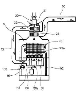
FIG. 8 shows an exemplary view of an upward combustion boiler with a fan
part for suction and exhaust 20 constructed in accordance with the principles
of the
present device. According to the present device, the upward combustion boiler
uses a
heating pin 93a, wherein the air in the room is forcedly sucked, while an
exhaust gas is
being forcedly exhausted to the outside, by virtue of the fan part for suction
and
exhaust 20.
FIG. 9 is a variation of FIG. 8, which shows another exemplary view of an
upward combustion boiler with the fan part for suction and exhaust 20
constructed in
accordance with the principles of the present device. According to the present
device,
the upward combustion boiler uses the heating pin 93a, wherein air is forcedly
sucked
from the outside, while an exhaust gas is being forcedly exhausted to the
outside, by
virtue of the fan part for suction and exhaust 20.
FIG. 10 shows still another exemplary view of an upward combustion boiler
with the fan part far suction and exhaust 20 constructed in accordance with
the
I S principles of the present device. According to the present device, the
upward
combustion boiler uses a combustion gas inducing tube 45, wherein the air in
the room
is forcedly sucked, while an exhaust gas is being forcedly exhausted to the
outside, by
virtue of the fan part for suction and exhaust 20.
FIG. 11 is a variation of F1G. 10, which shows still another exemplary view
of an upward combustion boiler with the fan part for suction and exhaust 20
constructed in accordance with the principles of the present device. According
to the
present device. the upward combustion boiler uses the combustion gas inducing
tube
45, wherein air is forcedly sucked from the outside, while an exhaust gas is
being
forcedly exhausted to the outside, by virtue of the fan part for suction and
exhaust 20.
9
CA 02348729 2001-06-05
FIG. 12 shows an exemplary view of a downward combustion boiler with the
fan part for suction and exhaust: 20 constructed in accordance with the
principles of the
present device. According to the present device, the downward combustion
boiler uses
the combustion gas inducing W be 45, wherein the air in the room is forcedly
sucked,
while an exhaust gas is being forcedly exhausted to the outside, by virtue of
the fan
part for suction and exhaust 20.
A heat exchanger 40 used in the preferred embodiments of the present device
includes: a cylindrical outer tank 41 having upper and lower openings closed
by means
of upper and lower caps 42 and 43; a combustion tube 44 and a plurality of
combustion gas inducing tubes 4S disposed in the interior of the outer tank
41, the
combustion tube 44 disposed eccentrically from the center of the outer tank
41; a water
chamber 46 formed between the outer tank 41, the upper and lower caps 42 and
43, the
combustion tube 44 and the plurality of combustion gas inducing tubes 45 in
manner
to be closed as the opened ends of the both sides of the combustion tube 44
and the
plurality of combustion gas inducing tubes 45 pass through the upper and lower
caps
42 and 43; and an inversion inducing chamber 47 formed on the lower portion of
the
lower cap 43.
According to the present device, when the heat exchanger 40 where the
combustion tube 44 and the combustion gas inducing tubes 45 are eccentrically
disposed is used. the exhaust gases from the plurality of combustion gas
inducing
tubes 45 are uniformly exhausted, thereby improving the heat exchanging
function
thereof.
FIG. 13 is a variation of FIG. 12, which shows another exemplary view of the
downward combustion boiler with the fan part for suction and exhaust 20
constructed
t0
CA 02348729 2001-06-05
in accordance with the principles of the present device. According to the
present
device, the downward combustion boiler uses the combustion gas inducing tube
45,
wherein air is forcedly sucked from the outside, while an exhaust gas is being
forcedly
exhausted to the outside, by virtue of the fan part for suction and exhaust
20.
The fan part for suctiion and exhaust 20 according to the present device is
comprised of a driving motor 21, a suction fan 22 secured on a rotary shaft of
the
driving motor 21 and disposed. on a suction line 12 or 13, for forcedly
sucking air in
the room or fram the outside, and an exhaust fan 23 secured on the rotary
shaft of the
driving motor 21 and disposed on an exhaust line 60, for forcedly exhausting
an
exhaust gas to the outside.
If the driving motor 2l is driven, the suction fan 22 and the exhaust fan 23
respectively fixed on the rotary shaft of the driving motor 21 are
simultaneously
rotated, with a result that the air in the room or from the outside is
forcedly sucked to
the suction line 12 or 13 by means of the suction fan 22 and the exhaust gas
is forcedly
exhausted to the exhaust line 60 by means of the exhaust fan 23.
In this way, the flowing of air is constantly kept in all of the suction,
combustion and exhaust lines, and a maximum amount of load of the driving
motor 21
is reduced.
As clearly appreciated from the foregoing, a combustion boiler according to
the present device has a fan part for suction and exhaust where air is
forcedly sucked
and an exhaust gas is forcedly exhausted, such that the flowing of air is
constantly kept
in all of the suction, combustion and exhaust lines, thereby improving the
inherent
functions of the boiler.
In addition, a maximum amount of load of a driving motor is greatly reduced,
CA 02348729 2001-06-05
such that the noises generated from the fan part can be suppressed and a small-
size fan
part can be embodied, thereby reducing the production cost.
12