Language selection

Search

Patent 2349026 Summary

Third-party information liability

Some of the information on this Web page has been provided by external sources. The Government of Canada is not responsible for the accuracy, reliability or currency of the information supplied by external sources. Users wishing to rely upon this information should consult directly with the source of the information. Content provided by external sources is not subject to official languages, privacy and accessibility requirements.

Claims and Abstract availability

Any discrepancies in the text and image of the Claims and Abstract are due to differing posting times. Text of the Claims and Abstract are posted:

  • At the time the application is open to public inspection;
  • At the time of issue of the patent (grant).
(12) Patent Application: (11) CA 2349026
(54) English Title: STORAGE RACK SYSTEM WITH FLARED END LOAD BEAM
(54) French Title: SUPPORTS DE RANGEMENT AVEC POUTRES DE CHARGE A BOUTS EVASES
Status: Deemed Abandoned and Beyond the Period of Reinstatement - Pending Response to Notice of Disregarded Communication
Bibliographic Data
(51) International Patent Classification (IPC):
  • A47B 01/00 (2006.01)
  • A47B 47/02 (2006.01)
  • A47B 96/14 (2006.01)
(72) Inventors :
  • KRUMMELL, JOHN V. R., JR. (United States of America)
(73) Owners :
  • ADVANCE STORAGE PRODUCTS
(71) Applicants :
  • ADVANCE STORAGE PRODUCTS (United States of America)
(74) Agent: SMART & BIGGAR LP
(74) Associate agent:
(45) Issued:
(22) Filed Date: 2001-05-29
(41) Open to Public Inspection: 2001-12-12
Availability of licence: N/A
Dedicated to the Public: N/A
(25) Language of filing: English

Patent Cooperation Treaty (PCT): No

(30) Application Priority Data:
Application No. Country/Territory Date
09/591,903 (United States of America) 2000-06-12

Abstracts

English Abstract


A storage rack has a spaced apart upright frames or vertical columns. Load
beams
extend between the upright frames. The load beams have flattened or flared
ends,
allowing the load beams to be directly bolted onto the vertical upright
frames. The use of
separate clips welded to the load beams is eliminated, reducing cost and
improving
reliability.


Claims

Note: Claims are shown in the official language in which they were submitted.

4
WHAT IS CLAIMED IS:
1. A storage rack comprising:
a pair of spaced apart upright frames; and
a load beam between and connecting to the upright frames, the load
beam having a channel section extending between flattened flared ends of the
load beam.
2. The storage rack of claim 1 wherein the channel section of the load
beam has a generally C-shaped cross section.
3. The storage rack of claim 1 wherein the channel section of the load beam
has an upper leg, a web joined to the upper leg, and a lower leg joined to the
web, and a
pair of mounting clearance holes.
4. The storage rack of claim 1 further including a pair of pallet
supports supported on one of the load beam and the upright frames.
5. The storage rack of claim 3 wherein the upper and lower legs are
formed as a single piece with the web.
6. A method of making a storage rack comprising the steps of:
cutting a beam channel section to a specified length to form a load
beam;
flattening the ends of the beam channel to form flared load beam
ends;
making a hole in the flared ends of the load beam; and
bolting the load beam onto an upright member, by placing bolts
through the hole in the flared ends of the load beam.
7. The method of claim 6 wherein the flattening step further comprises
placing the ends of the load beam in a press and pressing the ends until they
are
substantially flat.

5
8. The method of claim 7 wherein the load beam has first and second
legs joined to a web, and the load beam end are flattened until the legs are
approximately
parallel to the plane of the web.
9. The method of claim 6 wherein the flared load beam ends extends
from 10-30cm.
10. The storage rack of claim 1 with the upright frames attached to the
floor.
11. The storage rack of claim 1 wherein the flattened flared ends of the
load beam are directly attached to the upright frames via bolts.
12. The storage rack of claim 1 wherein the upright frames are
configured to be supported on a floor.
13. The storage rack of claim 12 wherein the upright frames are fixed to
the floor.
14. The storage rack of claim 1 wherein the load beam is constructed
from a standard steel channel section adapted for carrying pallets bearing
heaving loads.
15. A warehouse storage rack comprising:
a plurality of spaced apart upright frames;

6
a pair of load beams connected to two upright frames, the load beams each
having a channel section extending between flattened flared ends of the load
beam, with
the channel sections of the load beams facing one another.
16. The storage rack of claim 15 wherein the channel section of each
load beam has a generally C-shaped cross section.
17. The storage rack of claim 15 further including a plurality of pallet
supports attached to one of the upright frames and the load beams.
18. The storage rack of claim 15 wherein each flattened flared end of
each load beam is directly attached, to an upright frame via at least one
bolt.
19. A warehouse storage rack comprising:
a pair of spaced apart upright frames attached to a warehouse floor;
a load beam between and connecting to the upright frames, the load beam
having a channel section with a generally C-shaped cross section extending
between
flattened flared ends of the load beam; and
a pair of pallet supports supported on one of the load beam and the upright
frames for pallets carrying goods.
20. A warehouse storage rack comprising:
a pair of spaced apart upright frames attached to a floor; and
a load beam between and connecting to the upright frames, the load beam
having flared ends and a channel section extending between the flared ends of
the load

7
beam, the load beam constructed from a standard steel channel section adapted
for
carrying pallets in a warehouse bearing heaving loads;
a pair of pallet supports on the load beam; and
the load beam having an upper leg and a lower leg attached to a web
section and extending towards the upright frames.

Description

Note: Descriptions are shown in the official language in which they were submitted.


CA 02349026 2001-05-29
1
DESCRIPTION
STORAGE RACK SYSTEM WITH FLARED END LOAD BEAM
BACKGROL'r1D OF THE INVENTION
The field of the invention is warehouse storage racks.
Storage racks are frequently used in warehouses and other storage locations.
Storage racks allow materials and products to be stored easily, while still
providing quick
access, and while also maximizing; effective use of available space. Many
different styles
of storage racks have been successfully used. Typically, a storage rack has
upright frames
which are supported on or attached to the floor of the warehouse or other
location. Load
beams are typically attached to the' upright frames. Pallet supports or cart
rails are attached
to the load beams and/or the upright frames. Pallets carrying the goods or
materials to be
stored are typically placed onto thc: load beams.
For manufacturing efficiency, the upright frames, load beams, and pallet
supports
are often manufactured using standard steel channel sections. As the load
beams must be
attached perpendi<;ularly to the upright frames, in the past, clips have been
separately
made and attached (e.g., welded;) to the ends of the load beams, to attach the
load beams to
the upright frames, as shown in Fig. '7. While this design has worked well in
th:. past, it
requires separate manufacture of tine end clips, which increases the cost of
the storage rack
components. In addition, the end clips can fail due to defects in the welds
attaching the
end clip to the load beam.
Accordingly, there remains a need for an improved storage rack.
STATEMENT OF THE INVENTION
To this end, in a first aspect of the invention, a storage rack has a pair of
spaced
upright frames. .A load beam extends between the upright frames. The load beam
advantageously has a channel section and flattened or flared ends. The flared
ends have
clearance holes, allowing the load beam to be bolted directly to the upright
frames.
Manufacturing eff.~ciency is improved as fewer parts are needed. Reliability
is improved
as welding to manufacture the load beams is eliminated.
Other objects and advantages will appear hereinafter.

CA 02349026 2001-05-29
2
BRIEF DESCRIPTION OF THE DRAWINGS
In the drawings, wherein the same element number denotes the same element,
throughout the several views:
FIG. 1 is a perspective view of the new storage rack;
FIG. 2 is a perspective view of one end of the load beam of the storage rack
shown
in FIG. 1;
FIG. 3 is a side elevation view thereof;
FIG. 4 is an enlarged section view taken along line A-A of FIG. 3;
FIG. 5 is a side elevation view of the load beam shown in FIG. 1;
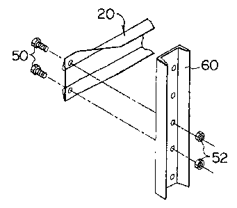
FIG. 6 is a. perspective view showing the attachment of the load beam shown in
FIGS. 2-5 t:o the upright or upright frame shown in FIG. 1; and
FIG. 7 is a perspective view of a prior art load beam.
DETAILED DESCRIPTION OF THE DRAWINGS
Turning now to the drawings, as shown in FIG. l, a storage rack l0 has upright
frames 12 supported on a .floor 14, typically in a warehouse. Diagonal braces
16 or other
stiffening members are attached to the upright frames 12. Horizontal load
beams 20 are
attached to the vertical upright dames 12. Pallet supports 22 may be attached
to the load
beam 20 and/or to the upright frames 12. Pallets may be placed on the load
beams 20.
Alternatively, rolling carts on rails may be used, as is well known in the
industry. The
design shown in 1FIG. 1 is illustrative of but one example of a storage rack.
Various
equivalent designs having different styles of braces, upright frames, load
beams, and pallet
supports, may of course be used.
Referring t:o FIGS. 2-5, the load beams 20 have a generally C-shaped channel
section. The channel section is shown in phantom line in FIG. 4. The load
beams 20 have
a top leg 30 and a bottom leg 34 joined to a central web 32. The ends of the
load beams
20 are flattened or flared. Clearance holes 38 pass through the flared ends 36
of the load
beams 20.
3C~ As shown in FIG. 6, this allows the load beams 20 to be directly bolted
onto an
upright frame 12 or a vertical column 60, via bolts 50 passing through the
clearance holes
38 and threaded into nuts 52 on the opposite side of the vertical column 60 or
upright
frame 12. Other attachment methods may also be used.

CA 02349026 2001-05-29
3
In contrast to the prior art design shown in FIG. 7, no separate clip 70 is
needed,
reducing the complexity and cost oi.-' the storage rack 10. In addition, the
welded joint 72
between the clip TO and load beam in the prior design, shown in FIG. 7, is
eliminated,
thereby improving the reliability of the storage rack, as failure due to
cracking in weld
joints is eliminated.
The load beams 20 are manufactured preferably using standard steel channel
sections or shapes. such as the C-section beam shown in phantom in FIG. 4. The
stock
steel channel sections are cut to the desired length, as shown in FIG. 5. The
ends of the
load beam 20 are then placed into a press, to flatten or flair the ends, so
that the inside
surface of the top leg 30 and bottom leg 34 is generally parallel to the plane
of the web 32,
as shown in FIG. 4. The clearance holes 38 are then drilled or punched in the
flared legs.
As shown in FIG. 6, the flared ends 36 allow the load beam 20 to be directly
attached to the vertical member via two fasteners, which securely and reliably
hold the
load beam onto the vertical member. The fasteners pass through the load beam
and
vertical member perpendicularly to the plane of the web.
The storage rack is used for storage of heavy loads, e.g., for pallets
carrying at least
a 100 ka load, arid more typically a 200 kg or higher load. The upright frames
are
preferably rigidly attached to the warehouse floor, e.g., with bolts. The load
beam is
preferably a structural c-channel hot rolled steel.

Representative Drawing
A single figure which represents the drawing illustrating the invention.
Administrative Status

2024-08-01:As part of the Next Generation Patents (NGP) transition, the Canadian Patents Database (CPD) now contains a more detailed Event History, which replicates the Event Log of our new back-office solution.

Please note that "Inactive:" events refers to events no longer in use in our new back-office solution.

For a clearer understanding of the status of the application/patent presented on this page, the site Disclaimer , as well as the definitions for Patent , Event History , Maintenance Fee  and Payment History  should be consulted.

Event History

Description Date
Application Not Reinstated by Deadline 2007-05-29
Inactive: Dead - RFE never made 2007-05-29
Deemed Abandoned - Failure to Respond to Maintenance Fee Notice 2007-05-29
Inactive: Abandon-RFE+Late fee unpaid-Correspondence sent 2006-05-29
Inactive: IPC from MCD 2006-03-12
Application Published (Open to Public Inspection) 2001-12-12
Inactive: Cover page published 2001-12-11
Letter Sent 2001-08-27
Inactive: First IPC assigned 2001-07-27
Inactive: Single transfer 2001-07-17
Inactive: Correspondence - Formalities 2001-07-10
Application Received - Regular National 2001-06-28
Inactive: Filing certificate - No RFE (English) 2001-06-28

Abandonment History

Abandonment Date Reason Reinstatement Date
2007-05-29

Maintenance Fee

The last payment was received on 2006-05-03

Note : If the full payment has not been received on or before the date indicated, a further fee may be required which may be one of the following

  • the reinstatement fee;
  • the late payment fee; or
  • additional fee to reverse deemed expiry.

Patent fees are adjusted on the 1st of January every year. The amounts above are the current amounts if received by December 31 of the current year.
Please refer to the CIPO Patent Fees web page to see all current fee amounts.

Fee History

Fee Type Anniversary Year Due Date Paid Date
Application fee - standard 2001-05-29
Registration of a document 2001-07-17
MF (application, 2nd anniv.) - standard 02 2003-05-29 2003-05-28
MF (application, 3rd anniv.) - standard 03 2004-05-31 2004-05-04
MF (application, 4th anniv.) - standard 04 2005-05-30 2005-05-04
MF (application, 5th anniv.) - standard 05 2006-05-29 2006-05-03
Owners on Record

Note: Records showing the ownership history in alphabetical order.

Current Owners on Record
ADVANCE STORAGE PRODUCTS
Past Owners on Record
JOHN V. R., JR. KRUMMELL
Past Owners that do not appear in the "Owners on Record" listing will appear in other documentation within the application.
Documents

To view selected files, please enter reCAPTCHA code :


To view images, click a link in the Document Description column. To download the documents, select one or more checkboxes in the first column and then click the "Download Selected in PDF format (Zip Archive)" or the "Download Selected as Single PDF" button.

List of published and non-published patent-specific documents on the CPD .

If you have any difficulty accessing content, you can call the Client Service Centre at 1-866-997-1936 or send them an e-mail at CIPO Client Service Centre.


Document
Description 
Date
(yyyy-mm-dd) 
Number of pages   Size of Image (KB) 
Representative drawing 2001-11-13 1 6
Description 2001-05-28 3 137
Abstract 2001-05-28 1 11
Claims 2001-05-28 4 100
Drawings 2001-05-28 3 77
Drawings 2001-07-09 2 64
Filing Certificate (English) 2001-06-27 1 163
Courtesy - Certificate of registration (related document(s)) 2001-08-26 1 136
Reminder of maintenance fee due 2003-01-29 1 106
Reminder - Request for Examination 2006-01-30 1 117
Courtesy - Abandonment Letter (Request for Examination) 2006-08-06 1 167
Courtesy - Abandonment Letter (Maintenance Fee) 2007-07-23 1 174
Correspondence 2001-06-27 1 29
Correspondence 2001-07-09 3 103
PCT 2001-02-16 3 186