Sélection de la langue

Search

Sommaire du brevet 2349026 

Énoncé de désistement de responsabilité concernant l'information provenant de tiers

Une partie des informations de ce site Web a été fournie par des sources externes. Le gouvernement du Canada n'assume aucune responsabilité concernant la précision, l'actualité ou la fiabilité des informations fournies par les sources externes. Les utilisateurs qui désirent employer cette information devraient consulter directement la source des informations. Le contenu fourni par les sources externes n'est pas assujetti aux exigences sur les langues officielles, la protection des renseignements personnels et l'accessibilité.

Disponibilité de l'Abrégé et des Revendications

L'apparition de différences dans le texte et l'image des Revendications et de l'Abrégé dépend du moment auquel le document est publié. Les textes des Revendications et de l'Abrégé sont affichés :

  • lorsque la demande peut être examinée par le public;
  • lorsque le brevet est émis (délivrance).
(12) Demande de brevet: (11) CA 2349026
(54) Titre français: SUPPORTS DE RANGEMENT AVEC POUTRES DE CHARGE A BOUTS EVASES
(54) Titre anglais: STORAGE RACK SYSTEM WITH FLARED END LOAD BEAM
Statut: Réputée abandonnée et au-delà du délai pour le rétablissement - en attente de la réponse à l’avis de communication rejetée
Données bibliographiques
(51) Classification internationale des brevets (CIB):
  • A47B 01/00 (2006.01)
  • A47B 47/02 (2006.01)
  • A47B 96/14 (2006.01)
(72) Inventeurs :
  • KRUMMELL, JOHN V. R., JR. (Etats-Unis d'Amérique)
(73) Titulaires :
  • ADVANCE STORAGE PRODUCTS
(71) Demandeurs :
  • ADVANCE STORAGE PRODUCTS (Etats-Unis d'Amérique)
(74) Agent: SMART & BIGGAR LP
(74) Co-agent:
(45) Délivré:
(22) Date de dépôt: 2001-05-29
(41) Mise à la disponibilité du public: 2001-12-12
Licence disponible: S.O.
Cédé au domaine public: S.O.
(25) Langue des documents déposés: Anglais

Traité de coopération en matière de brevets (PCT): Non

(30) Données de priorité de la demande:
Numéro de la demande Pays / territoire Date
09/591,903 (Etats-Unis d'Amérique) 2000-06-12

Abrégés

Abrégé anglais


A storage rack has a spaced apart upright frames or vertical columns. Load
beams
extend between the upright frames. The load beams have flattened or flared
ends,
allowing the load beams to be directly bolted onto the vertical upright
frames. The use of
separate clips welded to the load beams is eliminated, reducing cost and
improving
reliability.

Revendications

Note : Les revendications sont présentées dans la langue officielle dans laquelle elles ont été soumises.


4
WHAT IS CLAIMED IS:
1. A storage rack comprising:
a pair of spaced apart upright frames; and
a load beam between and connecting to the upright frames, the load
beam having a channel section extending between flattened flared ends of the
load beam.
2. The storage rack of claim 1 wherein the channel section of the load
beam has a generally C-shaped cross section.
3. The storage rack of claim 1 wherein the channel section of the load beam
has an upper leg, a web joined to the upper leg, and a lower leg joined to the
web, and a
pair of mounting clearance holes.
4. The storage rack of claim 1 further including a pair of pallet
supports supported on one of the load beam and the upright frames.
5. The storage rack of claim 3 wherein the upper and lower legs are
formed as a single piece with the web.
6. A method of making a storage rack comprising the steps of:
cutting a beam channel section to a specified length to form a load
beam;
flattening the ends of the beam channel to form flared load beam
ends;
making a hole in the flared ends of the load beam; and
bolting the load beam onto an upright member, by placing bolts
through the hole in the flared ends of the load beam.
7. The method of claim 6 wherein the flattening step further comprises
placing the ends of the load beam in a press and pressing the ends until they
are
substantially flat.

5
8. The method of claim 7 wherein the load beam has first and second
legs joined to a web, and the load beam end are flattened until the legs are
approximately
parallel to the plane of the web.
9. The method of claim 6 wherein the flared load beam ends extends
from 10-30cm.
10. The storage rack of claim 1 with the upright frames attached to the
floor.
11. The storage rack of claim 1 wherein the flattened flared ends of the
load beam are directly attached to the upright frames via bolts.
12. The storage rack of claim 1 wherein the upright frames are
configured to be supported on a floor.
13. The storage rack of claim 12 wherein the upright frames are fixed to
the floor.
14. The storage rack of claim 1 wherein the load beam is constructed
from a standard steel channel section adapted for carrying pallets bearing
heaving loads.
15. A warehouse storage rack comprising:
a plurality of spaced apart upright frames;

6
a pair of load beams connected to two upright frames, the load beams each
having a channel section extending between flattened flared ends of the load
beam, with
the channel sections of the load beams facing one another.
16. The storage rack of claim 15 wherein the channel section of each
load beam has a generally C-shaped cross section.
17. The storage rack of claim 15 further including a plurality of pallet
supports attached to one of the upright frames and the load beams.
18. The storage rack of claim 15 wherein each flattened flared end of
each load beam is directly attached, to an upright frame via at least one
bolt.
19. A warehouse storage rack comprising:
a pair of spaced apart upright frames attached to a warehouse floor;
a load beam between and connecting to the upright frames, the load beam
having a channel section with a generally C-shaped cross section extending
between
flattened flared ends of the load beam; and
a pair of pallet supports supported on one of the load beam and the upright
frames for pallets carrying goods.
20. A warehouse storage rack comprising:
a pair of spaced apart upright frames attached to a floor; and
a load beam between and connecting to the upright frames, the load beam
having flared ends and a channel section extending between the flared ends of
the load

7
beam, the load beam constructed from a standard steel channel section adapted
for
carrying pallets in a warehouse bearing heaving loads;
a pair of pallet supports on the load beam; and
the load beam having an upper leg and a lower leg attached to a web
section and extending towards the upright frames.

Description

Note : Les descriptions sont présentées dans la langue officielle dans laquelle elles ont été soumises.

CA 02349026 2001-05-29
1
DESCRIPTION
STORAGE RACK SYSTEM WITH FLARED END LOAD BEAM
BACKGROL'r1D OF THE INVENTION
The field of the invention is warehouse storage racks.
Storage racks are frequently used in warehouses and other storage locations.
Storage racks allow materials and products to be stored easily, while still
providing quick
access, and while also maximizing; effective use of available space. Many
different styles
of storage racks have been successfully used. Typically, a storage rack has
upright frames
which are supported on or attached to the floor of the warehouse or other
location. Load
beams are typically attached to the' upright frames. Pallet supports or cart
rails are attached
to the load beams and/or the upright frames. Pallets carrying the goods or
materials to be
stored are typically placed onto thc: load beams.
For manufacturing efficiency, the upright frames, load beams, and pallet
supports
are often manufactured using standard steel channel sections. As the load
beams must be
attached perpendi<;ularly to the upright frames, in the past, clips have been
separately
made and attached (e.g., welded;) to the ends of the load beams, to attach the
load beams to
the upright frames, as shown in Fig. '7. While this design has worked well in
th:. past, it
requires separate manufacture of tine end clips, which increases the cost of
the storage rack
components. In addition, the end clips can fail due to defects in the welds
attaching the
end clip to the load beam.
Accordingly, there remains a need for an improved storage rack.
STATEMENT OF THE INVENTION
To this end, in a first aspect of the invention, a storage rack has a pair of
spaced
upright frames. .A load beam extends between the upright frames. The load beam
advantageously has a channel section and flattened or flared ends. The flared
ends have
clearance holes, allowing the load beam to be bolted directly to the upright
frames.
Manufacturing eff.~ciency is improved as fewer parts are needed. Reliability
is improved
as welding to manufacture the load beams is eliminated.
Other objects and advantages will appear hereinafter.

CA 02349026 2001-05-29
2
BRIEF DESCRIPTION OF THE DRAWINGS
In the drawings, wherein the same element number denotes the same element,
throughout the several views:
FIG. 1 is a perspective view of the new storage rack;
FIG. 2 is a perspective view of one end of the load beam of the storage rack
shown
in FIG. 1;
FIG. 3 is a side elevation view thereof;
FIG. 4 is an enlarged section view taken along line A-A of FIG. 3;
FIG. 5 is a side elevation view of the load beam shown in FIG. 1;
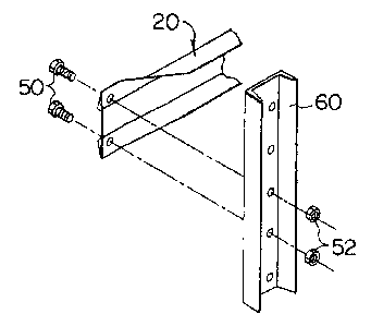
FIG. 6 is a. perspective view showing the attachment of the load beam shown in
FIGS. 2-5 t:o the upright or upright frame shown in FIG. 1; and
FIG. 7 is a perspective view of a prior art load beam.
DETAILED DESCRIPTION OF THE DRAWINGS
Turning now to the drawings, as shown in FIG. l, a storage rack l0 has upright
frames 12 supported on a .floor 14, typically in a warehouse. Diagonal braces
16 or other
stiffening members are attached to the upright frames 12. Horizontal load
beams 20 are
attached to the vertical upright dames 12. Pallet supports 22 may be attached
to the load
beam 20 and/or to the upright frames 12. Pallets may be placed on the load
beams 20.
Alternatively, rolling carts on rails may be used, as is well known in the
industry. The
design shown in 1FIG. 1 is illustrative of but one example of a storage rack.
Various
equivalent designs having different styles of braces, upright frames, load
beams, and pallet
supports, may of course be used.
Referring t:o FIGS. 2-5, the load beams 20 have a generally C-shaped channel
section. The channel section is shown in phantom line in FIG. 4. The load
beams 20 have
a top leg 30 and a bottom leg 34 joined to a central web 32. The ends of the
load beams
20 are flattened or flared. Clearance holes 38 pass through the flared ends 36
of the load
beams 20.
3C~ As shown in FIG. 6, this allows the load beams 20 to be directly bolted
onto an
upright frame 12 or a vertical column 60, via bolts 50 passing through the
clearance holes
38 and threaded into nuts 52 on the opposite side of the vertical column 60 or
upright
frame 12. Other attachment methods may also be used.

CA 02349026 2001-05-29
3
In contrast to the prior art design shown in FIG. 7, no separate clip 70 is
needed,
reducing the complexity and cost oi.-' the storage rack 10. In addition, the
welded joint 72
between the clip TO and load beam in the prior design, shown in FIG. 7, is
eliminated,
thereby improving the reliability of the storage rack, as failure due to
cracking in weld
joints is eliminated.
The load beams 20 are manufactured preferably using standard steel channel
sections or shapes. such as the C-section beam shown in phantom in FIG. 4. The
stock
steel channel sections are cut to the desired length, as shown in FIG. 5. The
ends of the
load beam 20 are then placed into a press, to flatten or flair the ends, so
that the inside
surface of the top leg 30 and bottom leg 34 is generally parallel to the plane
of the web 32,
as shown in FIG. 4. The clearance holes 38 are then drilled or punched in the
flared legs.
As shown in FIG. 6, the flared ends 36 allow the load beam 20 to be directly
attached to the vertical member via two fasteners, which securely and reliably
hold the
load beam onto the vertical member. The fasteners pass through the load beam
and
vertical member perpendicularly to the plane of the web.
The storage rack is used for storage of heavy loads, e.g., for pallets
carrying at least
a 100 ka load, arid more typically a 200 kg or higher load. The upright frames
are
preferably rigidly attached to the warehouse floor, e.g., with bolts. The load
beam is
preferably a structural c-channel hot rolled steel.

Dessin représentatif
Une figure unique qui représente un dessin illustrant l'invention.
États administratifs

2024-08-01 : Dans le cadre de la transition vers les Brevets de nouvelle génération (BNG), la base de données sur les brevets canadiens (BDBC) contient désormais un Historique d'événement plus détaillé, qui reproduit le Journal des événements de notre nouvelle solution interne.

Veuillez noter que les événements débutant par « Inactive : » se réfèrent à des événements qui ne sont plus utilisés dans notre nouvelle solution interne.

Pour une meilleure compréhension de l'état de la demande ou brevet qui figure sur cette page, la rubrique Mise en garde , et les descriptions de Brevet , Historique d'événement , Taxes périodiques et Historique des paiements devraient être consultées.

Historique d'événement

Description Date
Demande non rétablie avant l'échéance 2007-05-29
Inactive : Morte - RE jamais faite 2007-05-29
Réputée abandonnée - omission de répondre à un avis sur les taxes pour le maintien en état 2007-05-29
Inactive : Abandon.-RE+surtaxe impayées-Corr envoyée 2006-05-29
Inactive : CIB de MCD 2006-03-12
Demande publiée (accessible au public) 2001-12-12
Inactive : Page couverture publiée 2001-12-11
Lettre envoyée 2001-08-27
Inactive : CIB en 1re position 2001-07-27
Inactive : Transfert individuel 2001-07-17
Inactive : Correspondance - Formalités 2001-07-10
Demande reçue - nationale ordinaire 2001-06-28
Inactive : Certificat de dépôt - Sans RE (Anglais) 2001-06-28

Historique d'abandonnement

Date d'abandonnement Raison Date de rétablissement
2007-05-29

Taxes périodiques

Le dernier paiement a été reçu le 2006-05-03

Avis : Si le paiement en totalité n'a pas été reçu au plus tard à la date indiquée, une taxe supplémentaire peut être imposée, soit une des taxes suivantes :

  • taxe de rétablissement ;
  • taxe pour paiement en souffrance ; ou
  • taxe additionnelle pour le renversement d'une péremption réputée.

Les taxes sur les brevets sont ajustées au 1er janvier de chaque année. Les montants ci-dessus sont les montants actuels s'ils sont reçus au plus tard le 31 décembre de l'année en cours.
Veuillez vous référer à la page web des taxes sur les brevets de l'OPIC pour voir tous les montants actuels des taxes.

Historique des taxes

Type de taxes Anniversaire Échéance Date payée
Taxe pour le dépôt - générale 2001-05-29
Enregistrement d'un document 2001-07-17
TM (demande, 2e anniv.) - générale 02 2003-05-29 2003-05-28
TM (demande, 3e anniv.) - générale 03 2004-05-31 2004-05-04
TM (demande, 4e anniv.) - générale 04 2005-05-30 2005-05-04
TM (demande, 5e anniv.) - générale 05 2006-05-29 2006-05-03
Titulaires au dossier

Les titulaires actuels et antérieures au dossier sont affichés en ordre alphabétique.

Titulaires actuels au dossier
ADVANCE STORAGE PRODUCTS
Titulaires antérieures au dossier
JOHN V. R., JR. KRUMMELL
Les propriétaires antérieurs qui ne figurent pas dans la liste des « Propriétaires au dossier » apparaîtront dans d'autres documents au dossier.
Documents

Pour visionner les fichiers sélectionnés, entrer le code reCAPTCHA :


Pour visualiser une image, cliquer sur un lien dans la colonne description du document. Pour télécharger l'image (les images), cliquer l'une ou plusieurs cases à cocher dans la première colonne et ensuite cliquer sur le bouton "Télécharger sélection en format PDF (archive Zip)" ou le bouton "Télécharger sélection (en un fichier PDF fusionné)".

Liste des documents de brevet publiés et non publiés sur la BDBC .

Si vous avez des difficultés à accéder au contenu, veuillez communiquer avec le Centre de services à la clientèle au 1-866-997-1936, ou envoyer un courriel au Centre de service à la clientèle de l'OPIC.


Description du
Document 
Date
(aaaa-mm-jj) 
Nombre de pages   Taille de l'image (Ko) 
Dessin représentatif 2001-11-13 1 6
Description 2001-05-28 3 137
Abrégé 2001-05-28 1 11
Revendications 2001-05-28 4 100
Dessins 2001-05-28 3 77
Dessins 2001-07-09 2 64
Certificat de dépôt (anglais) 2001-06-27 1 163
Courtoisie - Certificat d'enregistrement (document(s) connexe(s)) 2001-08-26 1 136
Rappel de taxe de maintien due 2003-01-29 1 106
Rappel - requête d'examen 2006-01-30 1 117
Courtoisie - Lettre d'abandon (requête d'examen) 2006-08-06 1 167
Courtoisie - Lettre d'abandon (taxe de maintien en état) 2007-07-23 1 174
Correspondance 2001-06-27 1 29
Correspondance 2001-07-09 3 103
PCT 2001-02-16 3 186