Language selection

Search

Patent 2349254 Summary

Third-party information liability

Some of the information on this Web page has been provided by external sources. The Government of Canada is not responsible for the accuracy, reliability or currency of the information supplied by external sources. Users wishing to rely upon this information should consult directly with the source of the information. Content provided by external sources is not subject to official languages, privacy and accessibility requirements.

Claims and Abstract availability

Any discrepancies in the text and image of the Claims and Abstract are due to differing posting times. Text of the Claims and Abstract are posted:

  • At the time the application is open to public inspection;
  • At the time of issue of the patent (grant).
(12) Patent: (11) CA 2349254
(54) English Title: ARRANGEMENT FOR WINDING CABLES OR THE LIKE
(54) French Title: SYSTEME D'ENROULEMENT DE CABLES OU ANALOGUES
Status: Expired
Bibliographic Data
(51) International Patent Classification (IPC):
  • B65H 75/00 (2006.01)
  • B65H 54/553 (2006.01)
(72) Inventors :
  • LAUHDE, MIKA (Finland)
(73) Owners :
  • MAILLEFER S.A. (Not Available)
(71) Applicants :
  • NEXTROM HOLDING S.A. (Switzerland)
(74) Agent: CASSAN MACLEAN IP AGENCY INC.
(74) Associate agent:
(45) Issued: 2007-07-24
(86) PCT Filing Date: 1999-11-11
(87) Open to Public Inspection: 2000-05-25
Examination requested: 2004-08-23
Availability of licence: N/A
(25) Language of filing: English

Patent Cooperation Treaty (PCT): Yes
(86) PCT Filing Number: PCT/FI1999/000937
(87) International Publication Number: WO2000/029316
(85) National Entry: 2001-05-01

(30) Application Priority Data:
Application No. Country/Territory Date
982453 Finland 1998-11-12

Abstracts

English Abstract


The invention relates to an arrangement for winding a cable or the like on and
off a reel with a centre hole, which arrangement
comprises two movable, substantially vertical support arms (1), which are
supported by a frame structure and the free arm ends of which are
provided with spindles (2) arranged to be inserted to the centre holes of the
reel (3) between the support arms, when the support arms (1)
are being moved towards one another, whereby the reel can be raised from the
foundation by means of vertical adjustment of the support
arms (1) to enable the winding. To achieve a simple structure, the spindles
(2) are arranged floatably to the ends of the support arms (1)
allowing the spindles (2) to move freely in different directions. As a result
of the support arms moving towards one another and resting
against the centre hole of the reel (3), the spindles (2) are arranged to move
axially with respect to the support arms (1) into a position in
which the spindles (2) are locked to the support arms (1).


French Abstract

L'invention concerne un système de bobinage et de débobinage d'un câble ou analogue sur un touret comportant un trou central. Le système comprend deux bras de support (1) sensiblement verticaux, mobiles, qui sont maintenus par un cadre. Les extrémités libres desdits bras sont dotées de mandrins (2) destinés à être introduits dans les trous centraux du touret (3) entre les bras de support se déplaçant l'un vers l'autre. Le touret peut ainsi être soulevé de la base au moyen d'un ajustement vertical des bras de support (1) permettant l'enroulement. Afin d'obtenir une structure simple, les mandrins (2) sont montés flottants aux extrémités des bras de support (1), ce qui permet aux mandrins (2) de se déplacer librement dans différentes directions. Les bras de support, qui se déplacent l'un vers l'autre et qui s'appuient contre le trou central du touret (3), provoquent le déplacement axial des mandrins (2) par rapport aux bras de support (1) en une position dans laquelle les mandrins (2) se retrouvent bloqués contre les bras de support (1).

Claims

Note: Claims are shown in the official language in which they were submitted.


-5-
WHAT IS CLAIMED IS:

1. An arrangement for winding a cable or the like on and off a reel with a
centre hole,
which arrangement comprises two movable, substantially vertical support arts,
which are
supported by a frame structure and free arm ends of which are provided with
spindles
arranged to be inserted to the centre holes of the reel between the support
arms, when the
support arms are moved towards one another, whereby the reel can be raised
from the
foundation by means of vertical adjustment of the support arms to enable the
winding,
characterized in that the spindles are arranged floatably to the ends of the
support arms
making the spindles move freely in different directions and as a result of the
support arms
moving towards one another and resting against the centre hole of the reel,
the spindles
are arranged to move axially with respect to the spindle into a position in
which the spindles
are locked to the support arms.

2. An arrangement as claimed in claim 1, characterized in that the spindles
are
arranged to the support arms by means of spring means functioning in the
radial and axial
directions.

3. An arrangement as claimed in claim 1 or 2, characterized in that each
spindle is
provided with at least one guiding surface and at least one supporting lock
surface and that
a surface co-operating with the guiding surface and the supporting lock
surface is arranged
to the support arm, whereby as a result of the axial movement of the spindle
the guiding
surface and the co-operating surface are arranged to come into contact with
one another
and to bring the spindle into a position in which the spindle is locked by
means of the
supporting lock surface and the co-operating surface in the support arm to the
support arm.
4. An arrangement as claimed in claim 3, characterized in that the guiding
surface is
a conical surface.

5. An arrangement as claimed in claim 3 or 4, characterized in that the
supporting lock
surface is parallel to the symmetry axis of the spindle.

Description

Note: Descriptions are shown in the official language in which they were submitted.


CA 02349254 2001-05-01

WO 00/29316 PCT/F199/00937
1
ARRANGEMENT FOR WINDING CABLES OR THE LIKE

The invention relates to an arrangement for winding a cable or the
like on and off a reel with a centre hole, which arrangement comprises two
movable, substantially vertical support arms, which are supported by a frame
structure and the free arm ends of which are provided with spindles arranged
to be inserted to the centre holes of the reel between the support arms, when
the support arms are moved towards one another, whereby the reel can be
raised from the foundation by means of vertical adjustment to enable the
winding.
Such arrangements are well known from situations in which various
flexible elongated products are handled. The above arrangements have espe-
cially been used in cable manufacture, and the solutions disclosed in the Ger-
man Patent 27 13 866 (the Finnish Publication 60542) and the U.S. Patents 5
123 602 and 5 242 127 can be cited as examples thereof.
It is difficult to position the reel into the winder in practice, because
guiding of the spindles into the centre hole of the reel is not easy. To solve
this
problem, a variety of solutions has been developed, and they have been de-
scribed in the above-mentioned publications, for example.
A disadvantage of the above prior art solutions is, however, their
complex structure, whereby the manufacturing costs are high. A complex
structure also makes great demands on installation and adjustments, and im-
plementation and operating costs rise relatively high. Due to the complexity,
a
further disadvantage is that devices do not have the best possible
reliability,
and there is a big risk of malfunctions partly because the solutions are rela-
tively sensitive with respect to adjustments, as mentioned above.
It is an object of the invention to provide an arrangement to elimi-
nate the prior art disadvantages. This is achieved by the arrangement of the
invention. The arrangement of the invention is characterized in that the spin-
dles are arranged floatably to the ends of the support arms making the spin-
dles move freely in different directions, and that as a result of the support
arms
moving towards one another and resting against the centre hole of the reel,
the spindles are arranged to move axially with respect to the support arms
into
a position in which the spindles are locked to the support arms.
A particular advantage of the invention is its simplicity, whereby the
implementation and operating costs of the invention are kept low. Another ad-


CA 02349254 2001-05-01

WO 00/29316 PCT/F199/00937
2
vantage is the reliability of the arrangement. Further, a substantial
advantage
is that the arrangement of the invention can be implemented largely by using
the same parts as in normal fixed spindles. The invention provides also the
advantage that the arrangement of the invention can be applied to various
winders and it can further be applied to already existing winders without hav-
ing to make big structural changes.
In the following the invention will be described in greater detail by
means of a preferred embodiment illustrated in the attached drawing, in which
Figure 1 shows a schematic view of a winder, to which the invention
can be applied,
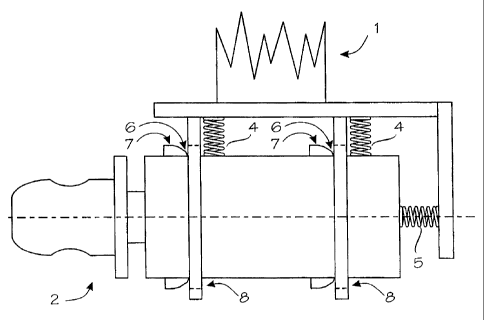
Figure 2 shows a schematic side view of the arrangement of the in-
vention,
Figure 3 shows the arrangement of Figure 2 seen in the direction of
the symmetry axis of the spindle,
Figure 4 shows a schematic side view of the arrangement of the in-
vention in a situation in which the spindle can move freely, and
Figure 5 shows a schematic side view of the arrangement of the in-
vention in a situation in which the spindle is locked to the support arm.
Figure 1 shows a schematic view of a winder. The winder com-
prises two movable support arms 1, which are substantially adjusted in the
vertical direction. The support arms 1 are arranged to be supported by the
frame structure in such a manner that they can be moved vertically and hori-
zontally. Spindles 2 are arranged to the free ends of the support arms 1,
which
spindles are arranged to be inserted to the centre hole of the reel 3 between
the support arms 1, when the support arms are moved horizontally towards
one another. When both spindles are in the centre hole of the reel, the reel
can be lifted from its foundation by raising the support arms vertically. When
the reel is supported by the spindles, it can be rotated in the desired
direction
depending on whether the cable or the like is wound on or off the reel.
The structure and operation of the winder constitute fully conven-
tional technology for a person skilled in the art, wherefore the above factors
will not be described in greater detail herein.
Figures 2 and 3 show the arrangement of the invention schemati-
cally. In Figure 2 same reference numbers as in Figure 1 are used to refer to
the corresponding items. As Figure 2 shows, the spindle 2 is arranged in a
freely floatable manner to the ends of the support arms 1. The wording


CA 02349254 2006-08-24

- 3 -

'floatable' means that the spindle 2 can move freely in different directions,
i.e. in all degrees
of freedom. On account of this fact, the spindles in a sense find their way to
the centre
hole of the reel 3 easier than before when the support arms 1 are moved
towards one
another, i.e. when the aim is to catch hold of the reel 3 and lift it up for
winding.
The spindle 2 can be arranged to the support arm 1 e.g. by means of spring
means
4 and 5 functioning radially and axially with respect to the spindle, as shown
e.g. in Figure
2. The floatable support of the spindle allows it to move axially when the
spindles are
supported by the centre hole of the reel and the support arms are moved
further towards
one another. The invention utilizes this factor as will be described in the
following.
As Figure 2 shows, the spindle 2 is provided with guiding surfaces 6 and
supporting
lock surfaces 7. A guiding surface 6 is preferably a conical surface and a
supporting lock
surface correspondingly a surface parallel to the symmetry axis of the
spindle. The above-
mentioned surfaces can preferably be implemented by projecting parts on the
outer surface
of the spindle, as in the example of Figure 2. The number of the above-
mentioned
surfaces may vary, when necessary. A surface 8 co-operating with the guiding
surface 6
and the supporting lock surface 7 is arranged to the support arm 1, the
surface 8 being
arranged to come into contact with the above-mentioned surfaces 6 and 7, when
the
spindle moves axially with respect to the support arm, as described above. The
surface
8 can be seen particularly well in Figure 3, which shows that the surface in
question is
composed of a hole, through which the spindle extends. The example of Figure 2
includes
two surfaces 8, but the number of surfaces may naturally vary, when necessary.
Figures 4 and 5 show the axial movement of the spindle, whereby the spindle is
supported by the centre hole of the reel and the support arms are moved
further towards
one another. In Figure 4 the spindle is in a free state, and in Figure 5 the
spindle moves
axially with respect to the spindle, as described above. As a result of this
movement, the
guiding surface 6 and the co-operating surface 8 in the support arm 1 come
into contact,
and if the movement continues, the spindle is funnelled into a position in
which the spindle
is locked by means of the supporting lock surface 7 and the co-operating
surface 8 to the
support arm 1. In Figure 5 the spindle is rigidly locked to the support arm,
and the reel can
be lifted by raising the support arms 1.


CA 02349254 2001-05-01

WO 00/29316 PCT/F199/00937
4
The above embodiment is not intended to restrict the invention in
any way, but the invention may be modified quite freely within the scope of
the
claims. Therefore it is obvious that the invention or the details thereof do
not
have to be exactly identical to those shown in the figures, but also other
solu-
tions are possible. For example, the spring means naturally need not be the
elements described in the figures, but other types of elements can also be
used for achieving the free floatability of the spindle. Spring means can be
e.g.
suitable rubber elements or the like. Although the invention has been de-
scribed above in connection with cable winding, it is obvious that the
invention
is not restricted solely to cable winding, but it may also be used in
connection
with other similar flexible elongated products, e.g. ropes, wires, yarns and
tubes.

Representative Drawing
A single figure which represents the drawing illustrating the invention.
Administrative Status

For a clearer understanding of the status of the application/patent presented on this page, the site Disclaimer , as well as the definitions for Patent , Administrative Status , Maintenance Fee  and Payment History  should be consulted.

Administrative Status

Title Date
Forecasted Issue Date 2007-07-24
(86) PCT Filing Date 1999-11-11
(87) PCT Publication Date 2000-05-25
(85) National Entry 2001-05-01
Examination Requested 2004-08-23
(45) Issued 2007-07-24
Expired 2019-11-12

Abandonment History

There is no abandonment history.

Payment History

Fee Type Anniversary Year Due Date Amount Paid Paid Date
Application Fee $300.00 2001-05-01
Registration of a document - section 124 $100.00 2001-09-05
Maintenance Fee - Application - New Act 2 2001-11-13 $100.00 2001-10-17
Maintenance Fee - Application - New Act 3 2002-11-12 $100.00 2002-10-31
Maintenance Fee - Application - New Act 4 2003-11-12 $100.00 2003-10-31
Request for Examination $800.00 2004-08-23
Maintenance Fee - Application - New Act 5 2004-11-11 $200.00 2004-10-19
Maintenance Fee - Application - New Act 6 2005-11-11 $200.00 2005-10-27
Maintenance Fee - Application - New Act 7 2006-11-13 $200.00 2006-10-23
Final Fee $300.00 2007-05-07
Maintenance Fee - Patent - New Act 8 2007-11-12 $200.00 2007-10-17
Maintenance Fee - Patent - New Act 9 2008-11-11 $200.00 2008-10-17
Registration of a document - section 124 $100.00 2009-03-30
Maintenance Fee - Patent - New Act 10 2009-11-11 $250.00 2009-10-20
Maintenance Fee - Patent - New Act 11 2010-11-11 $250.00 2010-10-18
Maintenance Fee - Patent - New Act 12 2011-11-11 $250.00 2011-10-17
Maintenance Fee - Patent - New Act 13 2012-11-13 $250.00 2012-10-17
Maintenance Fee - Patent - New Act 14 2013-11-12 $250.00 2013-10-17
Maintenance Fee - Patent - New Act 15 2014-11-12 $450.00 2014-11-10
Maintenance Fee - Patent - New Act 16 2015-11-12 $450.00 2015-11-09
Maintenance Fee - Patent - New Act 17 2016-11-14 $450.00 2016-11-07
Maintenance Fee - Patent - New Act 18 2017-11-14 $450.00 2017-11-06
Maintenance Fee - Patent - New Act 19 2018-11-13 $450.00 2018-11-05
Owners on Record

Note: Records showing the ownership history in alphabetical order.

Current Owners on Record
MAILLEFER S.A.
Past Owners on Record
LAUHDE, MIKA
NEXTROM HOLDING S.A.
SPIRT AVERT AG
Past Owners that do not appear in the "Owners on Record" listing will appear in other documentation within the application.
Documents

To view selected files, please enter reCAPTCHA code :


To view images, click a link in the Document Description column. To download the documents, select one or more checkboxes in the first column and then click the "Download Selected in PDF format (Zip Archive)" or the "Download Selected as Single PDF" button.

List of published and non-published patent-specific documents on the CPD .

If you have any difficulty accessing content, you can call the Client Service Centre at 1-866-997-1936 or send them an e-mail at CIPO Client Service Centre.


Document
Description 
Date
(yyyy-mm-dd) 
Number of pages   Size of Image (KB) 
Cover Page 2001-07-27 1 44
Representative Drawing 2001-07-27 1 8
Description 2001-05-01 4 213
Claims 2001-05-01 1 54
Drawings 2001-05-01 2 43
Description 2006-08-24 4 203
Claims 2006-08-24 1 46
Representative Drawing 2007-07-06 1 9
Cover Page 2007-07-06 1 45
Abstract 2001-05-02 1 55
Abstract 2007-07-18 1 55
Correspondence 2001-07-12 1 24
Assignment 2001-05-01 4 120
PCT 2001-05-01 9 339
Assignment 2001-09-05 2 63
Prosecution-Amendment 2004-08-23 2 53
Prosecution-Amendment 2006-08-24 5 196
Prosecution-Amendment 2006-02-24 3 103
Office Letter 2018-02-05 1 31
Correspondence 2007-05-07 1 36
Assignment 2009-03-30 9 472