Language selection

Search

Patent 2349351 Summary

Third-party information liability

Some of the information on this Web page has been provided by external sources. The Government of Canada is not responsible for the accuracy, reliability or currency of the information supplied by external sources. Users wishing to rely upon this information should consult directly with the source of the information. Content provided by external sources is not subject to official languages, privacy and accessibility requirements.

Claims and Abstract availability

Any discrepancies in the text and image of the Claims and Abstract are due to differing posting times. Text of the Claims and Abstract are posted:

  • At the time the application is open to public inspection;
  • At the time of issue of the patent (grant).
(12) Patent Application: (11) CA 2349351
(54) English Title: IMPROVED ELONGATE PLASTIC MEMBER AND METHOD AND APPARATUS FOR PROVIDING STRUCTURAL STRENGTH TO SAME
(54) French Title: PIECE EN PLASTIQUE ALLONGEE AMELIOREE, ET METHODE ET DISPOSITIF D'OBTENTION DE LA RESISTANCE STRUCTURALE DE CETTE PIECE
Status: Dead
Bibliographic Data
(51) International Patent Classification (IPC):
  • E04C 3/28 (2006.01)
  • E04C 3/29 (2006.01)
  • E04C 3/36 (2006.01)
(72) Inventors :
  • WINTERFELD, WILLIAM C. (United States of America)
(73) Owners :
  • WINTERFELD, WILLIAM C. (United States of America)
(71) Applicants :
  • WINTERFELD, WILLIAM C. (United States of America)
(74) Agent: SMART & BIGGAR
(74) Associate agent:
(45) Issued:
(22) Filed Date: 2001-05-31
(41) Open to Public Inspection: 2002-09-26
Availability of licence: N/A
(25) Language of filing: English

Patent Cooperation Treaty (PCT): No

(30) Application Priority Data:
Application No. Country/Territory Date
09/817,822 United States of America 2001-03-26

Abstracts

English Abstract


An apparatus for increasing the rigidity of an elongate plastic member having
a groove
formed in an exterior surface thereof is an elongate metal reinforcing member,
preferably having
a generally T-shaped cross section, the member being adapted for placement
into the groove so
that the member fits snugly into the groove. An improved elongate plastic
member has a
reinforcing member formed, preferably by roll forming, into a rigid structure,
preferably having a
substantially T-shaped cross-section when viewed end-on. The insert fits
tightly within a groove
in the plastic portion of the improved elongate plastic member. An elongate
plastic member is
provided structural strength by forming in the plastic member a groove adapted
so that a
reinforcing member will fit tightly within the groove and then placing a
reinforcing member into
the groove.


Claims

Note: Claims are shown in the official language in which they were submitted.


CLAIMS:

1. A method for increasing rigidity of an elongate plastic member, comprising:
supplying a metal reinforcing member having a principal axis and a cross-
section
perpendicular to the principal axis;
forming in an exterior surface of the elongate plastic member a groove adapted
so
that the reinforcing member fits tightly within the groove; and
placing the reinforcing member within the groove.

2. A method for increasing rigidity of an elongate plastic member according to
claim 1, wherein said cross-section is substantially T-shaped.

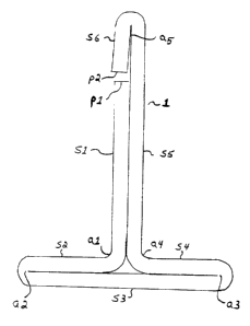
3. A method for increasing rigidity of an elongate plastic member according to
claim 2, wherein the cross-section of the reinforcing member defines a shape
having:
a thickness t;
a starting point p1;
a first segment of length L1, the first segment joining the starting point p1
to a
first angle a1;
a second segment of length L2, the second segment being essentially
perpendicular to the first segment and joining first angle al and a second
angle a2;
a third segment of length L3, L3 being approximately equal to two times the
length (L2 + t), the third segment running parallel and adjacent to the second
segment and joining second angle a2 and a third angle a3;

8


a fourth segment of length L4, L4 being approximately equal to L2, the fourth
segment running parallel and adjacent to the third segment and joining third
angle
a3 and a fourth angle a4;
a fifth segment of length L5, L5 being greater than L1, the fifth segment
running
parallel and adjacent to the first segment and joining fourth angle a4 and a
fifth
angle a5; and
a sixth segment of length L6, the sixth segment running parallel and adjacent
to
the first segment and joining fifth angle a5 and an end point p2.

4. A method for increasing the rigidity of an elongate plastic member
according to
claim 2, wherein the cross-section of the reinforcing member defines a shape
having:
a thickness t;
a starting point p1;
a first segment of length L1, the first segment joining the starting point p1
to a
first angle al;
a second segment of length L2, the second segment being essentially
perpendicular to the first segment and joining first angle al and a second
angle a2;
a third segment of length L3, L3 being approximately equal to twice the length
(L2 + t), the third segment running parallel and adjacent to the second
segment
and joining second angle a2 and a third angle a3;
a fourth segment of length L4, L4 being approximately equal to L2, the fourth
segment running parallel and adjacent to the third segment and joining third
angle
a3 and a fourth angle a4;

9


a fifth segment of length L5, L5 being greater than L1, the fifth segment
running
parallel and adjacent to the first segment and joining fourth angle a4 and a
fifth
angle a5; and
a sixth segment of length L6, L6 being slightly less than L minus L1, the
sixth
segment running adjacent to the fifth segment and forming an angle with said
fifth
segment of approximately 3 to approximately 5 degrees at a5, and joining fifth
angle a5 and an end point p2.

5. A method for increasing the rigidity of an elongate plastic member
according to
claim 2, wherein the groove is T-shaped and is adapted such that when the
reinforcing member is
placed in position in the groove, the base of the cross-section of the
reinforcing member is
recessed with respect to the surface of the elongate plastic member.

6. A method for increasing the rigidity of an elongate plastic member
according to
claim 3, wherein the reinforcing member is formed from sheet metal.

7. A method for increasing the rigidity of an elongate plastic member
according to
claim 4, wherein the reinforcing member is formed from sheet metal.

8. A method for increasing the rigidity of an elongate plastic member
according to
claim 6, wherein the reinforcing member is formed from sheet metal by a
process comprising
rolling.

9. A method for increasing the rigidity of an elongate plastic member
according to
claim 7, wherein the reinforcing member is formed from sheet metal that is
formed by a process
comprising rolling.

101


10. A method for reinforcing an elongate plastic member according to claim 4,
further
comprising the step of incorporating the reinforced elongate plastic member
into a structure.

11. A method of reinforcing an elongate plastic member according to claim 10,
wherein the reinforced plastic member is incorporated into the structure so as
to bear a load.

12. A method of reinforcing an elongate plastic member according to claim 11,
wherein the structure is a fence.

13. A method of reinforcing an elongate plastic member according to claim 12,
wherein the reinforced elongate plastic member forms at least one fence post.

14. A method of reinforcing an elongate plastic member according to claim 12,
wherein the reinforced elongate plastic member forms at least one segment of
the fence rail.

15. A method of reinforcing an elongate plastic member according to claim 10,
wherein the plastic member is made from recycled plastic material.

16. A method of reinforcing an elongate plastic member according to claim 10,
wherein the metal reinforcing member is made of steel.

17. An apparatus for increasing the rigidity of an elongate plastic member
having a
groove formed in an exterior surface thereof, comprising:
an elongate metal member, the member being adapted for placement into the
groove so that the member fits snugly into the groove.

18. An apparatus for increasing the rigidity of an elongate plastic member
according
to claim 17, wherein the elongate metal member has a cross-section
perpendicular to its principal
axis, the cross-section being generally T-shaped.


19. An apparatus for increasing the rigidity of an elongate plastic member
according
to claim 18, wherein the elongate metal member has a cross-section
perpendicular to its principal
axis, the cross-section defining a shape having:
a thickness t;
a starting point p1;
a first segment of length L1, the first segment joining the starting point p1
to a
first angle a1;
a second segment of length L2, the second segment being essentially
perpendicular to the first segment and joining first angle al and second angle
a2;
a third segment of length L3, L3 being approximately equal to twice the length
(L2 + t), the third segment running parallel and adjacent to the second
segment
and joining second angle a2 and a third angle a3;
a fourth segment of length L4, L4 being approximately equal to L2, the fourth
segment running parallel and adjacent to the third segment and joining third
angle
a3 and a fourth angle a4;
a fifth segment of length L5, L5 being greater than L1, the fifth segment
running
parallel and adjacent to the first segment and joining fourth angle a4 and a
fifth
angle a5; and
a sixth segment of length L6, the sixth segment running parallel and adjacent
to
the first segment and joining fifth angle a5 and an end point p2.


20. An apparatus for increasing the rigidity of an elongate plastic member
according
to claim 18, wherein the elongate member has a cross-section perpendicular to
its principal axis,
the cross-section defining a shape having:
a thickness t;
a starting point p1;
a first segment of length L1, the first segment joining the starting point p1
to a
first angle a1;
a second segment of length L2, the second segment being essentially
perpendicular to the first segment and joining first angle al and a second
angle a2;
a third segment of length L3, L3 being approximately equal to two times the
length (L2 + t), the third segment running parallel and adjacent to the second
segment and joining second angle a2 and a third angle a3;
a fourth segment of length L4, L4 being approximately equal to L2, the fourth
segment running parallel and adjacent to the third segment and joining third
angle
a3 and a fourth angle a4;
a fifth segment of length L5, L5 being greater than L1;, the fifth segment
running
parallel and adjacent to the first segment and joining fourth angle a4 and a
fifth
angle a5; and
a sixth segment of length L6, L6 being slightly less than L5 minus L1, the
sixth
segment running adjacent to the fifth segment and forming with said fifth
segment
an angle of approximately 3 to approximately 5 degrees at a5, and joining
fifth
angle a5 and an end point p2.

13


21. An apparatus for increasing the rigidity of an elongate plastic member
according
to claim 20, wherein the reinforcing member is formed from sheet metal.

22. An apparatus for increasing the rigidity of an elongate plastic member
according
to claim 21, wherein the reinforcing member is formed from sheet metal that is
formed by a
process comprising rolling.

23. An apparatus for increasing the rigidity of an elongate plastic member
according
to claim 22, wherein the apparatus is made of steel.

24. An improved elongate plastic member having a principal axis, comprising:
an elongate plastic member having a groove in one exterior surface thereof
parallel to the principal axis of the elongate plastic member; and
an elongate metal member adapted for insertion into and inserted into the
groove
so that the elongate metal member fits tightly within the groove.

25. An improved elongate plastic member according to claim 24, wherein said
reinforcing member has a cross-section perpendicular to its principal axis,
the cross-section
being generally T-shaped.

26. An improved elongate plastic member according to claim 25, wherein the
elongate metal member has a cross-section perpendicular to its principal axis,
the cross-section
defining a shape having:
a thickness t;
a starting point p1;
a first segment of length L1, the first segment joining the starting point p1
to a
first angle a1;
14


a second segment of length L2, the second segment being essentially
perpendicular to the first segment and joining first angle a1 and a second
angle a2;
a third segment of length L3, L3 being approximately equal to twice the length
(L2 + t), the third segment running parallel and adjacent to the second
segment
and joining second angle a2 and a third angle a3;
a fourth segment of length L4, L4 being approximately equal to L2, the fourth
segment running parallel and adjacent to the third segment and joining third
angle
a3 and a fourth angle a4;
a fifth segment of length L5, L5 being greater than L1, the fifth segment
running
parallel and adjacent to the first segment and joining fourth angle a4 and a
fifth
angle a5; and
a sixth segment of length L6, the sixth segment running parallel and adjacent
to
the first segment and adjoining fifth angle a5 and an end point p2.

27. An improved elongate plastic member according to claim 25, wherein the
elongate metal member has a cross-section perpendicular to its principal axis,
the cross-section
defining a shape having:
a thickness t;
a starting point p1;
a first segment of length L1, the first segment joining the starting point p1
to a
first angle a1;
a second segment of length L2, the second segment being essentially
perpendicular to the first segment and joining first angle a1 and a second
angle a2;


a third segment of length L3, L3 being approximately equal to twice the length
(L2 + t), the third segment running parallel and adjacent to the second
segment
and joining second angle a2 and a third angle a3;
a fourth segment of length L4, L4 being approximately equal to L2, the fourth
segment running parallel and adjacent to the third segment and joining third
angle
a3 and a fourth angle a4;
a fifth segment of length L5, L5 being greater than L1, the fifth segment
running
parallel and adjacent to the first segment and joining fourth angle a4 and a
fifth
angle a5; and
a sixth segment of length L6, L6 being less than L5 minus L1, the sixth
segment
running adjacent to the fifth segment and forming an angle with said fifth
segment
of approximately 3 to approximately 5 degrees, and joining fifth angle a5 and
an
end point p2.

28. An improved elongate plastic member according to claim 28, wherein the
reinforcing member is formed from sheet metal.

29. An improved elongate plastic member according to claim 28, wherein the
reinforcing member is formed by a process comprising rolling.

Description

Note: Descriptions are shown in the official language in which they were submitted.


CA 02349351 2001-05-31
TITLE OF INVENTION: Improved Elongate Plastic Member and Method and
Apparatus for Providing Structural Strength to Same
CROSS-REFERENCE TO RELATED APPLICATIONS:
Not applicable.
COPYRIGHT STATEMENT:
Not applicable.
FEDERAL RESEARCH STATEMENT:
Not applicable.
BACKGROUND OF THE INVENTION:
1. Field of the Invention.
The invention relates to an improved plastic lumber and to an improved method
and
apparatus for providing structural strength to plastic lumber. Plastic lumber
is a class of building
materials that are made from plastic and intended to be used foi the same
purposes and
applications as traditional wooden lumber. Plastic lumber provides several
advantages over
wooden lumber. Plastic lumber is less susceptible than wood to rotting,
splitting, moisture
absorption, mildew, termite and rodent attacks, and fire.
2. Description of the Related Art.
Plastic lumber is superior to traditional wooden lumber in most respects, but
plastic
lumber is not as stiff or strong (particularly in sheer, bending, and torsion)
as wooden lumber.
Therefore, plastic lumber is insufficient for some applications because it is
not rigid enough to
withstand a required loading without suffering failure or excessive
deformation.
2

CA 02349351 2001-05-31
For example, plastic lumber has been used in building fences. Plastic lumber
works well
for the fence boards or planks, the (typically) vertical members that make up
most of the body of
a fence. However, plastic lumber lacks the rigidity to serve as either fence
posts (the vertical
supports for the fence which are typically anchored in the ground) or the
fence rails (the typically
horizontal load-bearing members to which the fence pickets or fence boards are
attached).
One method of resolving the problem created by the lack of rigidity of plastic
lumber is
to use plastic lumber for non-load-bearing portions of a given structure while
using traditional
wooden lumber for load-bearing members. However, building a structure using
wooden load-
bearing members with plastic lumber non-load-bearing members reduces the
benefits of the
longer life of plastic lumber because the wooden load-bearing members of the
construction will
fail at the end of their normal life span, requiring the structure to be
rebuilt or repaired just as
often as an all-wood construction. Accordingly, it is an object of the ciu-
rent invention to
reinforce plastic lumber structural members so that load-bearing elements of
structures can be
constructed of plastic lumber.
The assembly of structures made from unreinforced plastic lumber requires
different
procedures and different tools from those used for the construction of
structures made from
wooden lumber. A further object of this invention is to provide an improved
plastic lumber that
will allow contractors to construct objects from plastic lumber using the same
tools and
procedures that they currently use with wooden lumber.
Plastic lumber may be reinforced by adding chemical or composite
reinforcements to the
plastic lumber material. However, these approaches are costly and often do not
add sufficient
rigidity to make the plastic lumber suitable for use in load-bearing members.
Accordingly, it is
3

CA 02349351 2001-05-31
an object of this invention to provide a cost-effective improved plastic
lumber and a cost-
effective method and apparatus for increasing the rigidity of plastic lumber.
Plastic lumber members have been reinforced by using metallic inserts. United
States
Patent No. 3,767,504 to Singleton describes a method of reinforcing a plastic
bar member by
providing a rigid metal reinforcing strip having a rectangular cross section,
forming a groove in
the plastic bar, positioning the metal reinforcing member in the groove,
placing a strip of plastic
over the reinforcing bar and applying beads of molten plastic over the strip
to bond to the strip
and to each side of the groove by melting and solidifying in sequence.
United States Patent No. 5,862,642 to Erwin describes a reinforced composite
deck post
that comprises an elongate, hollow, extruded plastic shell, the plastic shell
having a rectangular
cross-section. The plastic shell has an upper end and a lower end and has a
notch formed therein
adjacent to the lower end for receiving a wood joist of a wood deck. The
reinforced composite
deck post also includes an elongate metal stiffening member positioned within
the plastic shell
and rigidly secured thereto, generally adjacent to the upper end of the
plastic shell. Upper and
lower shim means are positioned within the plastic shell adjacent to the metal
stiffening member
for securing the metal stiffening member to the plastic shell. Erwin discloses
a metal reinforcing
member that is trapezoidal in cross-section and is manufactured by bending or
otherwise forming
flat sheet metal, preferably G-90 galvanized steel with a wall thickness of
0.100 inches, into the
desired shape. The reinforcing member is rigidly secured to an inside face of
the plastic outer
shell by wedges or shims. The invention also includes a crush-resistant insert
used to prevent the
metal stiffening member from being crushed when the bottom end of the
reinforced post is
attached to a joist.
4

CA 02349351 2001-05-31
There remains a need for an improved metallic insert for plastic lumber that
allows ease
of assembly and an uncomplicated, yet effective method for stiffening plastic
lumber.
SUMMARY OF INVENTION:
The present invention provides an improved apparatus and method for increasing
the
rigidity of an elongate plastic member, and also provides an improved plastic
lumber having
increased structural rigidity.
According to the present invention there is provided a reinforcing member,
preferably
having a substantially T-shaped cross-section when viewed end-on, that is,
when viewed
perpendicular to the long or principal axis of the reinforcing member. The
reinforcing member
preferably comprises a thin sheet of metal bent or otherwise formed into a "T"
shape. The T-
shaped metal insert is inserted into a corresponding groove or cut-out,
preferably also T-shaped,
in one side of a length of plastic lumber. When inserted, the reinforcing
member fits snugly in
the groove and imparts rigidity to the plastic member. The plastic member can
be plastic lumber
used in fence posts or fence rails or can be plastic members used in other
load-bearing
applications.
BRIEF DESCRIPTION OF THE DRAWINGS:
Fig. 1 is an end view of a reinforcing member according to a preferred
embodiment of the
invention.
Fig. 2 is an end view of a reinforcing member according to an alternative
embodiment of
the invention.

CA 02349351 2001-05-31
Fig. 3 shows an end view of a plastic member according to the invention,
showing a
preferred embodiment of a reinforcing member inserted into a corresponding
groove in the
plastic member.
DETAILED DESCRIPTION OF THE INVENTION:
Referring more specifically to the several views of the drawing, Fig. 1
discloses
reinforcing member 1 which embodies the present invention, and which comprises
a generally
rectangular sheet of reinforcing material, preferably metal that has been
formed, preferably by
roll forming, into a rigid structure having a substantially T-shaped cross-
section when viewed
end-on. The T-shaped structure defines segments Sl through S6 having
corresponding lengths
L1 through L6. The segments are continuous, but adjacent segments define
angles al through
a5.
The reinforcing material is preferably 16 gauge galvanized steel.
Alternatively, the
reinforcing material can be other metals, such as copper, aluminum or tin, can
be hard plastic, or
can be a composite material. The key properties are rigidity, with some
resiliency or memory,
sufficient to allow an insert comprising the reinforcing material to be snugly
inserted into a
corresponding grooved portion of a plastic member. Any reinforcing material
used may be any
cross-sectional shape that will accommodate a 180 degree bend. Stainless
steel, aluminum,
cooper, and reinforced fiberglass are some alternatives.
The dimensions of the reinforcing material are typically 1/16 inch thick, 1-
1/8 inch high,
and of a width sufficient to span most or all of the plastic member into which
an insert made
from the material is inserted. A principal axis is defined along the width.
For a typical
application, as shown in Fig. 3, plastic member 3 has a grooved or cut-off
portion 4, defining a
6

CA 02349351 2001-05-31
T-shaped groove into which a reinforcing insert 1 is inserted. Insert 1 has
member segments SS
and S6 forming an approximately 3 degree to an approximately S degree angle so
that, once
inserted, the outer corner of end p2 digs into inner wall S of plastic member
3, resulting in a tight
fit and impeding easy removal of insert 1.
In an alternative embodiment shown in Fig. 2, insert 2 is formed so that
segment S6
overlaps segment S1. Segments S5 and S6 of insert 2 can likewise form an angle
so that the
outer corner of end p2 digs into inner wall S of plastic member 3, resulting
in a tight fit and
impeding easy removal of insert 2.
The dimensions of the grooved or cut-out portion 4 of plastic member 3 can be
selected
so that insert 1 or insert 2 can be pressed into groove or cut-out portion 4
to form a press fit.
preferably, groove or cut-out portion 4 is sized so that when insert 1 or
insert 2 is placed into
position, the insert is recessed within plastic member 3 so that no portion of
the insert protnzdes
beyond a plane formed on an exterior surface of the plastic member.
The plastic member can be plastic lumber sized for use as fence posts or fence
rails. The
plastic member can comprise recycled waste thermoplastic resin, or,
alternatively, cellulose fiber
aggregate.
Persons or ordinary skill in the art can appreciate that the invention
disclosed and claimed
herein is not restricted to the embodiments shown and described, and that
various modifications
are within the true scope of the invention as claimed.
7
.. .......... .. ..._._.~.."~.,.... . ........ . .....n__.~~,....,..-
....~....~.........__......._... _ ..... ........

Representative Drawing
A single figure which represents the drawing illustrating the invention.
Administrative Status

For a clearer understanding of the status of the application/patent presented on this page, the site Disclaimer , as well as the definitions for Patent , Administrative Status , Maintenance Fee  and Payment History  should be consulted.

Administrative Status

Title Date
Forecasted Issue Date Unavailable
(22) Filed 2001-05-31
(41) Open to Public Inspection 2002-09-26
Dead Application 2004-05-31

Abandonment History

Abandonment Date Reason Reinstatement Date
2003-06-02 FAILURE TO PAY APPLICATION MAINTENANCE FEE

Payment History

Fee Type Anniversary Year Due Date Amount Paid Paid Date
Application Fee $150.00 2001-05-31
Owners on Record

Note: Records showing the ownership history in alphabetical order.

Current Owners on Record
WINTERFELD, WILLIAM C.
Past Owners on Record
None
Past Owners that do not appear in the "Owners on Record" listing will appear in other documentation within the application.
Documents

To view selected files, please enter reCAPTCHA code :


To view images, click a link in the Document Description column. To download the documents, select one or more checkboxes in the first column and then click the "Download Selected in PDF format (Zip Archive)" or the "Download Selected as Single PDF" button.

List of published and non-published patent-specific documents on the CPD .

If you have any difficulty accessing content, you can call the Client Service Centre at 1-866-997-1936 or send them an e-mail at CIPO Client Service Centre.


Document
Description 
Date
(yyyy-mm-dd) 
Number of pages   Size of Image (KB) 
Description 2001-05-31 6 247
Description 2001-05-31 9 313
Drawings 2001-05-31 3 21
Representative Drawing 2002-02-14 1 4
Abstract 2001-05-31 1 23
Cover Page 2002-09-03 1 37
Claims 2002-09-26 9 313
Assignment 2001-05-31 2 84