Note: Descriptions are shown in the official language in which they were submitted.
CA 02349369 2001-05-31
1
H-204303
METHOD FOR OPERATING A COMBINATION PARTIAL
OXIDATION AND STEAM REFORMING FUEL PROCESSOR
Field of the Invention
This invention relates to a method for
operating a combination partial oxidation and steam
reforming fuel processor.
Background of the Invention
Fuel cells have been used as a power source in
many applications. Fuel cells have also been proposed
for use in electrical vehicular power plants to replace
internal combustion engines. In proton exchange membrane
(PEM) type fuel cells, hydrogen is supplied to the anode
of the fuel cell and oxygen is supplied as the oxidant to
the cathode. PEM fuel cells include a "membrane
electrode assembly" (MEA) comprising a thin, proton
transmissive, non-electrically conductive, solid polymer
membrane-electrolyte having the anode on one of its faces
and the cathode on the opposite face. The MEA is
sandwiched between a pair of electrically conductive
elements which (1) serve as current collectors for the
anode and cathode, and (2) contain appropriate channels
and/or openings therein for distribution of the fuel
cell's gaseous reactants over the surfaces of the
respective anode and cathode catalysts. A typical PEM
fuel cell and its membrane electrode assembly (MEA) are
described in United States Patent Nos. 5,272,017 and
CA 02349369 2001-05-31
2
5,316,871, issued respectively December 21, 1993 and May
31, 1994, and assigned to General Motors Corporation,
assignee of the present invention, and having as
inventors Swathirajan et al. A plurality of individual
cells are commonly bundled together to form a PEM fuel
cell stack. The term fuel cell is typically used to
refer to either a single cell or a plurality of cells
(stack) depending on the context. A group of cells
within the stack is referred to as a cluster. Typical
arrangements of multiple cells in a stack are described
in U.S. Patent No. 5,763,113, assigned to General Motors
Corporation.
In PEM fuel cells hydrogen (H=) is the anode
reactant (i.e., fuel) and oxygen is the cathode reactant
(i.e., oxidant). The oxygen can be either a pure form
(Oz), or air (a mixture primarily containing O= and Nz).
The solid polymer electrolytes are typically made from
ion exchange resins such as perfluoronated sulfonic acid.
The anode/cathode typically comprises finely divided
catalytic particles, which are often supported on carbon
particles, and admixed with a proton conductive resin.
The catalytic particles are typically costly precious
metal particles. These membrane electrode assemblies
which comprise the catalyzed electrodes, are relatively
expensive to manufacture and require certain controlled
conditions in order to prevent degradation thereof.
For vehicular applications, it is desirable to
use a liquid fuel, such as methanol (MeOH), gasoline,
diesel, and the like, as the source of hydrogen for the
fuel cell. Such liquid fuels for the vehicle are easy to
CA 02349369 2001-05-31
3
store onboard and there is a nationwide infrastructure
for supplying liquid fuels. However, such fuels must be
dissociated to release the hydrogen content thereof for
fueling the fuel cell. The dissociation reaction is
accomplished Within the primary reactor of the fuel
processor. The primary reactor has a catalyst mass and
yields a reformate gas comprising primarily hydrogen and
carbon dioxide. A conventional exemplary process is the
steam methanol reformation process where methanol and
water (as steam) are ideally reacted to generate hydrogen
and carbon dioxide according to this reaction:
CH30H+HzO~CO~+3Hz .
Fuel cell systems which process a hydrocarbon
fuel to produce a hydrogen-rich reformate for consumption
by PEM fuel cells are known and are described in co-
pending United States Patent Application Serial No.
08/975,422 filed in November, 1997 and U. S. Patent No.
6,077,620, issued June 20, 2000, in the name of William
Pettit, and U.S. Serial No. 09/187,125, Glenn W. Skala et
al., filed November 5, 1998, and each assigned to General
Motors Corporation, assignee of the present invention.
In U.S. Patent No, 4,650,722, issued March 17, 1987,
Vanderborgh et al. describe a fuel processor comprising a
catalyst chamber encompassed by combustion chamber. The
combustion chamber is in indirect heat transfer
relationship with the catalyst chamber and the
hydrocarbon is being reformed in the presence of the
catalyst.
The indirect heat transfer arrangement between
the combustion chamber and catalyst chamber results in
CA 02349369 2001-05-31
4
extensive time required to heat the catalyst bed to a
temperature suitable for fuel reformation. Often, a
catalyst regenerating cycle is required to restore the
properties of the catalyst after periods of reformation.
Therefore, it is desirable to have a method which
provides rapid heating of the catalyst beds and timely
regeneration of such beds in a reformer.
Sugary of the Invention
In one aspect, the invention provides a method
for operating a fuel cell system. The system comprises a
reactor having one or more catalytic beds and is fed a
hydrocarbon fuel along with air and steam. Where more
than one catalytic bed is present, such catalytic beds
are preferably arranged sequentially such that the outlet
from one bed enters the inlet of the next bed. The
catalytic beds are the regions where reactions among the
hydrocarbon, air, and steam are catalyzed within the
reactor. The method comprises supplying a stream of a
fuel and air mixture to the reactor which is lean. The
mixture is lean in that it has an excess amount of oxygen
relative to the stoichiometric amount required for
reaction with the fuel. The reactions occurring with the
lean mixture heat the reactor. When there is more than
one catalytic bed, the hot gases generated from one
catalytic bed can be used to heat other or subsequent
catalytic beds. When a single bed is used, the hot gases
generated at an upstream end of the bed heat the
downstream portions) of the bed. After sufficient
heating of the reactor by the lean mixture, a fuel-rich
stream is fed to the reactor. This fuel-rich mixture
CA 02349369 2001-05-31
5
comprises fuel, air, and water in the form of steam. The
mixture is rich in that fuel is fed in an excess amount
relative to the amount of oxygen for a stoichiometric
reaction. The reactions of the fuel-rich stream produce
a product comprising hydrogen (Hz). Other typical
components of the product stream are carbon dioxide,
carbon monoxide, nitrogen, water, and methane.
In another aspect, following the lean fuel-air
mixture, a steam stream is fed to the reactor to purge
the reactor. Subsequent to the purge, a fuel-rich fuel
and air mixture is fed to the reactor along with steam.
In one preferred aspect, the first catalytic bed
preferentially oxidizes the fuel with oxygen in the
fuel/air mixture. The second catalytic bed provides for
further reaction and preferentially catalyzes the
products from the first catalytic bed with steam for the
production of a product comprising hydrogen and other
components. In the case where a single bed is used,
three main reactions, partial oxidation, steam reforming
and high temperature shift occur in the same bed. The
regions of the bed over which such reactions occur
typically overlap and change with changing power levels.
One of the advantages of this method is the
prevention of, or reduction of, carbon formation. Carbon
formation tends to degrade the catalyst on the catalytic
beds and decrease the reactor's operating life. Carbon
formation also plugs the reactor and decreases flow
through one or more of the catalytic beds.
CA 02349369 2001-05-31
6
Brief Description of the Drawings
The various features, advantages and other uses
of the present invention will become more apparent by
referring to the following description and drawings in
which:
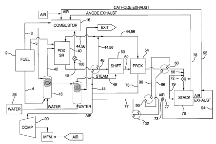
Figure 1 is a flow diagram depicting a fuel
cell apparatus which includes an autothermal reformer
constructed and operated according to the invention.
Figure 2 is a sectioned side view of an
autothermal reformer in accordance with the invention.
Figure 3 is a graph which contains plots
showing carbon formation as a function of steam/carbon
ratio. This demonstrates carbon formation problems
occurring with conventional reformer start-up.
Figure 4 is a graph containing plots showing
the lean start of the partial oxidation reactor section
of the autothermal refozmer using lean conditions of
oxygen to carbon (O: C) mole ratio of 10:1 for preheating
the partial oxidation catalyst to a suitable temperature.
Figure 5 is a graph which contains plots
showing lean start of the partial oxidation reactor using
an electric heater to heat inlet gases for the lean
start-up (light-off) method of the invention.
Figure 6 is a graph containing plots showing
operation of the POX from an initial start-up in the fuel
CA 02349369 2001-05-31
7
lean condition and transitioning to the fuel-rich
operation during the normal operating mode of a fuel cell
system.
Detailed Description of the Preferred ~nbodiments
A preferred system to convert hydrocarbons such
as gasoline into a hydrogen-rich stream is shown in
Figure 1. A fuel tank 2 supplies ambient temperature
liquid fuel such as gasoline to the fuel cell system
through fuel supply line 4 which delivers liquid fuel to
a heated vaporizer 18 Where the liquid fuel is converted
to a gas. Fuel tank 2 also supplies fuel to a combustor
via line 3. In addition, fuel from fuel tank 2 is
supplied through vaporizer 18 and line 42 to an
autothermal refozzner 40. In another embodiment, liquid
fuel is supplied through line 5 to the fuel cell system.
Water from tank 26 is also supplied into
vaporizer 18. The heater/vaporizer 18 causes both the
fuel and water to vaporize therein and provides both
steam and fuel vapor to the autothermal reformer 40 via
line 42. The temperature of the steam/fuel mixture is
between about 100°C and 600°C. In another embodiment,
the water and fuel vaporizers are separate.
In the exemplary and preferred autothermal
reformer 40, the moist fuel and water vapor is mixed with
air from line 44 and passes sequentially through two
reaction sections. A first section is designated a
CA 02349369 2001-05-31
8
partial oxidation (POX) section. The second section is
designated a steam reforming (SR) section. It should be
understood that there is some overlap in the type of
reactions occurring in the POX and SR sections. POX
implies predominantly reaction between fuel and air and
SR implies predominantly reaction between fuel and water.
The invention is described herein with reference to
these predominant reactions, however, it is to be
understood that since fuel, water (steam) and air are
added together the POX and SR combined perform as an
autothermal reactor. In an autothermal reactor, the
predominantly POX reactions are exothermic and the
predominantly SR reactions are endothermic, so that as
much as possible or all of the heat generated in the POX
is carried into the SR. In the POX section, the fuel
reacts exothermally with a sub-stoichiometric amount of
air to produce carbon monoxide, hydrogen and lower
hydrocarbons such as methane. The reaction in the POX
section is fuel-rich. The hot POX reaction products,
along with steam introduced with the fuel, pass into the
SR section where the lower hydrocarbons react with steam
to produce a reforaiate gas comprising principally carbon
dioxide, carbon monoxide, hydrogen, nitrogen, water, and
methane. The steam refozming reaction is endothermic.
Heat required for this endothermic reaction is provided
from the heat that is generated by the exothermic POX
reaction and is carried forward ixito the SR section by
the POX section effluent. Reformate exits the refoz~er
40 via line 46 and is cooled by heat exchanger 48. The
heat exchanger 48 concurrently preheats air supplied via
lines 44 to provide heated air in line 56 which is fed
into the autothermal reactor 40. Reformate exiting the
CA 02349369 2001-05-31
9
heat exchanger 48 enters a catalytic water gas shift
reactor 50 and therein reacts with steam supplied through
line 49 to produce carbon dioxide and hydrogen from the
carbon monoxide and water. Herein, the tezin reformer 40
refers to autothermal reformer 40.
The shift reactor includes one or more sections
(not shown). In one embodiment, there is provided a high
temperature shift section and a low temperature shift
section. Preferably, cooling of the refoz~ate stream
occurs between the high temperature and the low
temperature sections. Reformate exiting the shift
reactor 50 via line 52 enters a preferential oxidation
PROX reactor 54 where it is catalytically reacted with
oxygen in either heated air supplied through line 56 or
unheated air supplied through line 75. This reaction is
conducted to consume essentially all of, or at least most
of, the residual carbon monoxide without consuming excess
quantities of hydrogen in PROX reactor 54. The air
supplied through line 56 comes indirectly from compressor
90 via heat exchanger 48 that preheats the air to a
temperature desired, up to 800°C for reformer 40,
depending on operational conditions. The PROX air is
supplied through lines 56 and/or 75 to deliver air
preferably at an average temperature of about 200°C to a
PROX inlet plenum. In an alternative embodiment, PROX
air supply is not preheated and is supplied through line
75. The desired PROX air inlet temperature will depend
on system conditions. It may be desirable to not preheat
or even to cool the PROX air supply.
CA 02349369 2001-05-31
10
PROX effluent exits the PROX reactor 54 via
line 58 and is cooled by heat exchanger 60 to a
temperature suitable for use in fuel cell stack 76.
Cooling is preferably conducted to a temperature below
about 100°C. If desired, air in line 77 is preheated in
heat exchanger 93 by heat exchange fluid in line 96.
Thus, in one embodiment, fluid in line 96 accepts heat
rejected by PROX effluent in exchanger 60 and delivers it
to air in line 77 via exchanger 93.
As mentioned earlier, in the case where a
single bed is used, three main reactions zones are
identifiable, a partial oxidation zone, a steam reforming
zone, and a high temperature shift zone, each of which
may occur utilizing the same catalytic bed. The regions
of the bed over which such reactions occur typically
overlap and change with changing power levels. For
example, at low power level, the partial oxidation
typically takes place at the very leading edge of the
catalytic bed and the downstream portion of the bed is .
reforming. A still further downstream portion of the bed
catalyzes a high temperature shift reaction. At full
power in one embodiment, the catalytic bed is designed to
accomplish partial oxidation and steam reforming. In a
down turn situation, the downstream or back end of the
bed will perform as a high tempezature shift. This is a
natural design consequence since in a turn down situation
all the capacities of the bed will not be required for
reforming. In short, as compared to a full power
condition, the partial oxidation section will be
relatively shortened and the high temperature shift
CA 02349369 2001-05-31
11
section will be relatively larger, in the autothermal
reformer 40.
Exemplary reaction temperatures of the process
can be found in the literature, and by way of background
are provided here as a teaching tool. The autothermal
reformer reactions are conducted at a temperature of
about 600°C to 1000°C; the high temperature shift at a
temperature in the range of 300 to 600°C; the low
temperature shift at a temperature below 300°C; the PROX
at a temperature less than the shift; and the fuel cell
at a temperature less than the PROX and suitable for the
delicate MEA components.
Air supplied through line 77 is reacted in fuel
cell stack 76 with reformate exiting the PROX. The
reformate is supplied through line 58 to the fuel cell
stack 76. In fuel cell stack 76, the hydrogen-rich
reformate in line 58 reacts with air supplied through
line 77 in an electrochemical reaction in the presence of
the catalyst whereby electrical energy is produced and
water is generated as a by-product of the reaction.
If desired, a small amount of air from line 77
is diverted to line 58 reformate via line 79 to help
mitigate the effects of any carbon monoxide contamination
of the catalyst in fuel cell stack 76. The reformate in
stream 58 enters fuel cell stack for reaction and then
exits the stack as an anode tailgas or exhaust via line
78. The anode tailgas exiting stack 76 via line 78 is
fed to combustor 16 where it is consumed to produce heat.
A diverter valve 72 is located in line 58 that supplies
CA 02349369 2001-05-31
12
the stack and is used to divert the reforznate exiting the
PROX away from fuel cell stack 76 when required, such as
during start-up. The diverter valve 72 reroutes PROX
effluent (reforznate) into line 78. Air in line 77 may
likewise be diverted using valve 73.
Preferably, air is admitted to the system via a
mass flow meter (MFM) and is compressed via compressor
90. In one embodiment, air supply from line 44 is cooled
in exchanger 102 before being supplied as the oxidant to
the fuel cell through line 77. Air supplied through line
77 to the stack which is not completely consumed in the
stack exits the stack as cathode exhaust in line 95 where
it is supplied to the combustor. A diverter valve 73 is
located in air line 77 so that air in line 77 is able to
be directed around stack 76 through line 94 and to line
95. Thus, air and reformate are routed around stack 76
via diverters 72 and 73 as needed.
Figure 2 is a side sectional view of a
preferred autothermal reformer 40 which comprises POX and
steam reforming sections. The autothermal reformer 40
comprises a metal housing 158 which is lined with several
layers of insulation 161, 163 and 165. A mat insulating
material comprises vexzaiculite. The autothermal reformer
40 has an input end 164 for receiving fuel and air during
start-up and for receiving steam/fuel and air mixture
during operation of the fuel cell system after start-up.
The autothermal refox~er 40 has an outlet end 166
through which hot combustion exhaust gases are discharged
during start-up (warm-up) before normal operation of the
fuel cell system. Outlet end 166 serves to supply
CA 02349369 2001-05-31
13
reformate stream 46 to the downstream shift reactor 50
during normal operation of the system when steam, fuel
and air are being supplied during normal production of
reformate. The outlet end 166 comprises suitable
mounting and adaptors (not shown) for supplying reformate
downstream to the shift reactor 50 and for discharging
combustion exhaust gases during the warm-up cycle. A
first bed of gas mixing and distribution foam 170 is
positioned adjacent input end 164. This section 170
preferably comprises a ceramic foam type media to act as
a homogenization region for homogenizing the mixture
entering the autothermal reformer. Mixing or
homogenization of the fuel and air during lean burn
start-up occurs in this region. During normal operation,
steam/fuel and air are mixed in this region. Preferred
mixing and gas distribution media comprise ceramic foams
having a porosity profile of about 25 to 80 pores per
linear inch, but other materials may also be used. An
electric heating element 178 is provided downstream of
the mixing section 170 and serves to preheat
fuel/steam/air entering the reformer 40 during the warm-
up cycle. The heating element 178 may or may not be
catalyzed and is energized electrically by conventional
means. In one alternative, the electric element is used
to complete the vaporization of incoming fuel and/or
initiate the reactions. A preferred electric heater 178
comprises an uncatalyzed extruded metal monolith
resistance element. Downstream of electric heater 178 is
another mixing and distribution foam bed 180. Foam bed
180 serves to further mix the gaseous constituents
therein. As per Figure 2, the diameter of metal housing
158 is enlarged after bed 180. Bed 182 is of media
CA 02349369 2001-05-31
14
similar to bed 180. Bed 182 has a greater cross
sectional area which causes reduced gas velocity. Bed
184 is downstream of bed 182. Bed 184 is also of ceramic
foam media, but has a greater number of pores per linear
inch, as compared to bed 182. Thus, bed 184 provides a
higher velocity profile to act as a flame suppressor.
Accordingly, bed 184 prevents ignition and flash back
from the downstream POX section.
As per the above, preferred mixing and
distribution media comprises ceramic foams having a
porosity profile of about 25 pores per linear inch to
about 80 pores per linear inch (ppi), but other materials
and porosity profiles may be used. A preferred mixing-
media for beds 170, 180 and 182 comprises silicon carbide
foam having a preferred porosity profile of about 25
pores per linear inch and a thickness of about one inch.
Alternative mixing-media beds include refractory metal
foams, ceramic pellets retained in a flow-through
container, or a stack of fine (e. g., about 0.001 to about
0.010 openings per inch) metal or ceramic screens,
wherein the openings of one screen are offset from the
openings in adjacent screens to provide the desired
tortuous path. The mixing-media bed 184 can also
function as a flame suppressor to prevent any flame from
propagating back toward the input end 164, and as a means
to distribute the reaction mixture. Thus, bed 184 is
near the high end of the 25 to 80 ppi range, and beds
170, 180 and 182 have lesser ppi than bed 184.
The next downstream sections of the autothermal
reactor 40 contain the partial oxidation (POX) section
CA 02349369 2001-05-31
15
190 steam reformer section 192 which are used to convert
hydrocarbons (gasoline) into hydrogen and carbon monoxide
as in Figure 2. A preferred POX catalyst comprises one
or more noble metals, Pt, Rh, Pd, Ir, Os, Au, Ru. Other
non-noble metals, or combination of metals, such as Ni
and Co, are also useable. A noble metal or a non-noble
metal is typically used as the steam reforming catalyst.
The catalysts are typically supported upon a ceramic
material, and supported on a substrate such as a
cordierite monolith or Yttria stabilized Zirconia
reticulated foam. In the case of a foam, the porosity,
in ppi as expressed above, is between 10 and 80 ppi
range. The downstream shift reactor 50 typically
contains Fe0 and CuZn catalysts, and the PROX reactor
typically contains a noble metal catalyst.
The above-described autothermal reactor 40 is
used in a mode of operation which avoids carbon formation
during processing of hydrocarbon fuels. Carbon formation
is a significant difficultly in conventional reformer
operations. Carbon formation during steam reforming of
higher hydrocarbons (>C6) is generally considered
unavoidable. During normal 'steady-state' operation of a
conventional partial oxidation/steam reforming reactor
the conditions (temperature, stream gas composition) are
sought to be maintained sa that the tendency to form
carbon is reduced. This is very difficult in a rich
start-up, and avoiding carbon formation is very difficult
and complex controls are needed to minimize carbon
formation. A great difficulty in starting a partial
oxidation/steam reforming reactor is the inability to
preheat the reactor in a reasonably rapid time frame.
CA 02349369 2001-05-31
16
Thus, during heat up of the steam reforming reactor using
a rich start, equilibrium favors carbon formation.
Figure 3 shows equilibrium calculations for carbon
formation as a function of temperature and steam/carbon
HzO:C ratio. In Figure 3, the designation m.f.
represents mole fraction. Here, one mole of oxygen is
one mole of oxygen atoms. It is clear that at
temperatures less than 600°C, a non-zero carbon
equilibrium exists for steam/carbon ratios in a given
range, thus it is essentially inevitable that as the
catalyst heats up from a cold start, carbon formation
will occur. After the reactor has been started multiple
times, the carbon build-up prevents the reactor from
operating effectively, both poisoning the catalyst and
decreasing flow.
As shown in Figure 3, it is essential to start
a POX reactor at relatively high oxygen to carbon (O/C)
ratios. This results in a relatively high adiabatic
temperature rise while avoiding carbon (soot) deposition
as the steam to carbon (Hs0/C) ratios are relatively
lower. It is advantageous to start the POX with high O/C
ratio to avoid carbon (soot) formation when little or no
water is available. The excess oxygen (relative to
stoichiometric) also acts to oxidize any carbon deposits
previously formed. As seen in Figure 3, as the
temperature is increased above 700°C, carbon equilibrium
reaches essentially zero for steam to carbon ratio
greater than one. Note that the steam to carbon ratio is
alternatively expressed as HZO/C or S/C.
CA 02349369 2001-05-31
17
Thus, operation of a POX/steam reformer,
producing hydrogen as it heats up to normal operating
temperature, could produce potentially significant coke
(soot) levels. Starting the reactor under conditions
closer to stoichiometric conditions (higher O/C) creates
a temperature rise too great for the materials typically
used in such a reactor (1200°C). The time required for
start-up of a fuel processor for vehicle fuel cell is a
problem. Minimizing start-up time is desirable.
The start-up procedure for the partial
oxidation/steam reforDner (autothermal reformer) of the
present invention avoids carbon formation and is
appropriate to vehicle driving needs. This start-up
strategy incorporates a lean combustion process to start
the POX/steam reformer comprised of POX section 190 and
reformer section 192. The POX/steam reformer is started
lean. Reference to lean indicates that more air is used
than is required stoichiometrically. As used here,
stoichiometric refers to the amount of oxygen required to
oxidize the fuel thereby producing hot gases. Assuming a
fuel composition CeHle, the reaction is C8H18 + 12.502 = 8
COz + 9H~0. Here, the stoichiometric oxygen to carbon
atomic ratio is O:C of 25:8. A preferred lean start-up
mixture has O:C of 10:1. Therefore, considerable excess
oxygen and correspondingly excess air (nitrogen plus
oxygen) is used. This excess air produces a diluent
effect to keep the temperature of the hot gases below a
level which would degrade the ceramic and/or catalytic
materials. Reference to fuel-rich means that the O:C
ratio is less than 25:8. This fuel-rich condition is
implemented after fuel lean start-up. Thus, the reaction
CA 02349369 2001-05-31
18
is above the carbon formation temperature shown in Figure
3 when rich operation commences.
During start-up, the hot gases heat up the
reactor catalyst beds in sections 190 and 192, and
simultaneously regenerate the catalyst by oxidizing any
residual carbon from prior operation. In one embodiment,
after reaching an appropriate temperature throughout the
entire catalyst bed (600 - 700°C), the combustion is
stopped. Next, excess air is purged from the reactor
preferably by steam captured from the combustion process.
Then, fuel is fed to the reactor followed by appropriate
amount of air for rich operation of the reactor. Upon
the fuel/water/air mixture reaching the POX catalyst, or
an ignition source, ignition provides a rich burn
producing hydrogen and CO without significant carbon
formation.
More specifically, the invention provides a
method for operating the POX/SR to react hydrocarbon with
at least one of water and air to produce a product which
comprises hydrogen. The invention provides a method for
start-up and preheat of the reactor, and then operation
of the reactor thereafter to produce the hydrogen-rich
product stream. The reactor has a reaction chamber with
an inlet and an outlet and one or more catalytic beds.
Preferably, there are at least two catalytic beds. The
two main reactions, partial oxidation and reforming are
described with reference to one or more catalytic beds.
This is a design choice. The alternatives include a
graded bed, one with graded physical features; or
multiple beds of varying configurations to control the
CA 02349369 2001-05-31
19
reaction profile as desired. Preferably, the first
catalytic bed 190 comprises a catalyst supported on a
carrier which preferentially catalyzes reaction with
oxygen. The second catalytic bed 192 comprises a second
catalyst supported on a carrier which preferentially
catalyzes reaction with water. The second catalytic bed
192 is arranged downstream with respect to the reactor
inlet. In the method, a first stream is provided which
comprises a lean fuel and air mixture which flows through
the reactor to heat the reactor. The lean mixture
contains a sub-stoichiometric amount of fuel relative to
oxygen. As a result, there is essentially complete
combustion in the first catalytic bed 190 of the reactor
and the hot product gases of combustion carry through the
second catalytic bed 192 whereby both beds are heated.
Preferably, after the lean burn, a steam purge
is conducted. In this alternative, the supply of the
lean mixture is terminated and the reactor is purged with
steam. Next, the supply of steam is terminated and a
second reaction mixture is provided to the reactor which
is a fuel-rich mixture. This fuel-rich mixture comprises
fuel, air and steam which react within the two catalytic
beds to provide the hydrogen-rich product. The rich
mixture contains a sub-stoichiometric amount of oxygen
relative to the fuel. The process is used on subsequent
start-up if needed based on the conditions. If the
catalyst bed is warm on a hot restart, the lean
combustion would not be needed.
In another alternative, after the supply of the
lean mixture and reaction thereof to heat the reactor,
CA 02349369 2001-05-31
20
the fuel/air ratio is ix~ediately adjusted to provide the
fuel-rich mixture accompanied by the supply of steam. In
still another alternative, the supply of the lean mixture
is terminated, the steam is supplied to purge the
reactor, and then the supply of steam is continued while
the fuel and air is supplied to provide the fuel-rich
mixture.
To initiate the lean burn, it is preferred to
start the air supply first, then add fuel to it. To
commence fuel-rich operation, it is preferred to start in
the following supply sequence, steam, fuel, then air.
The order may be selected based on criteria such as
process control and catalyst character.
The lean and the rich combustion may occur in a
variety of ways on a catalyst, as a flame, or a
combination of a flame for lean start-up, and catalyst
for rich operation. This allows simple flame ignition,
or a catalyst ignition. The catalyst ignition optionally
includes a low temperature light-off catalyst or an
electrically heated catalyst.
In the lean burn start-up it is possible to
control temperature of the reaction by varying air/fuel
ratio. As the catalyst downstream of the reaction heats
up, carbon will be burned by the excess oxygen in the
air, thus regenerating the catalyst bed, and removing any
residual carbon. Carbon is oxidized typically at about
500 to about 600°C. Because the lean start has excess
oxygen, there will not be carbon formation, because
carbon equilibrium formation is zero, even though the
CA 02349369 2001-05-31
21
catalyst is cold upon start. The reactor heating up
under lean mode to the required temperature for rich
operation is easier to control and may be faster than if
run under a rich mode from the start. This is because
under lean start-up, the reactor temperature will be
limited only by the total amount of air flow through the
reactor catalyst sections. Internal reaction flow (void)
volume is defined by the catalyst material contained
therein. Under a rich start scenario, the limitation is
how much unconverted HC's (hydrocarbons) the rest of the
fuel processor 16 can accept.
A lean start of the reactor requires that the
catalysts either not be air sensitive, or be able to be
re-reduced with full activity after oxidation during lean
burn. Preferably, the POX/steam reformer catalysts are
noble metal catalysts. Pt/Rh are useable for the POX.
Rh has been demonstrated to be an active steam reforming
catalyst. The excess oxygen could be fed to the
combustor with the POX exhaust and further fuel could be
added to the combustor, hence utilizing all of the
available oxygen. The result is a reduction in
compressor work. This occurs because the partial
oxidation is run lean at start-up, so the exhaust
contains oxygen as well as combustor by-products. This
oxygen from the lean burn reaction in reformer 40 is
reusable in the combustor delivered via valve 100.
Figure 4 shows a small scale light-off of a
POX/steam reformer reactor under lean conditions (O/C =
10, power level = 1.2 kW) after preheating the partial
oxidation catalyst to 350°C. TC6 is a type K
CA 02349369 2001-05-31
22
thermocouple placed just after the partial oxidation
catalyst bed in section 190. The downstream thermocouple
TC9 is in the beginning of the steam reforming bed.
Thermocouple TC6 is after the POX and TC9 is after
reformer inlet mixing distribution foam. Figure 4 shows
the light-off of the POX reaction under lean conditions
without using an electric catalyst heater. The graph
shows lean ignition combustion from time 250 to time 475
seconds. This graph shows that the process functions
properly, but the heat and mass transport were not
optimal for this test which was operated under manual
control conditions. This test shows the feasibility, and
when viewed in the context of Figure 3, the advantages of
the method of the invention.
Figure 5 shows a full scale light-off of a
POX/steam refozmer reactor under lean conditions (O/C =
10, power level 6.3 kW). In this case, an electrical
heater, similar to electrically heated catalysts
developed for catalytic converters, is used to preheat
the inlet gases to the POX to initiate light-off of the
reactor. This is~faster than that shown in Figure 4.
TC5 is a thermocouple just after the electric heater 178.
Thermocouple TC7 is in reformer 40 after POX section 190
and thermocouple TC8 is in reforming section 192 of
Figure 2.
Figure 5 shows that the electric heater is
required only for a short time to achieve light-off of
the POX catalyst. The light-off time is reduced using
the electrically heated catalyst. This also depicts
design of the reactor to match the lean combustion space
CA 02349369 2001-05-31
23
velocity and normal operational parameters of the fuel-
rich operating conditions space velocity. This is
demonstrated by the stable combustion which occurred for
10 minutes as shown in Figure 5. The temperature
variations are primarily due to the manual control of
this example.
Figure 6 shows a POX/steam refozsner reactor
switching from lean operation to rich operation. At time
- 2410 sec, the fuel is shut off to the reactor, and the
temperature of the reactor starts to drop. Air is shut
off at 2420 sec, and steam is used to purge the reactor
volume of air, starting at t = 2420 sec. At t = 2490
sec, the fuel and air are again added to the reactor at
an O/C of 1.0 to relight the POX. At this point, the POX
relights and rises to the normal partial oxidation
temperature of about 900°C. Figure 6 shows the process
of an actual lean burn, steam purge, rich burn sequence
of operation. Thermocouple TC7 represents the
temperature of the POX catalyst where, in lean burn, the
combustion is taking place, and the heat of combustion is
transported downstream to the reformer, where the
temperature is measured with TC6 and TC8. Duriag the
steam purge, it is evident that the temperature drops as
no reaction is taking place. Since this test was
conducted manually, the duration of the steam purge Was
relatively long. Upon introduction of the fuel and air
in addition to the steam, at time 2480 seconds, it is
evident that the reaction begins and stabilizes at
approximately 900°C. It is evident that the reformer
temperatures are close to the POX outlet due to the
CA 02349369 2001-05-31
24
oxygen to carbon ratio being approximately equal to one,
where no steam reforming endotherm is occurring.
The invention provides the advantages of
eliminating carbon formation during the start-up period
of the POX/SR reactor. An additional benefit is that the
catalyst is regenerated every time the reactor is started
from a cold start to its steady state operating
temperature by means of the lean burn start of the
invention. The preheating of the reactor by the method
of the invention is preferably combined with a non-
reducing/oxidizing steam reforming catalyst such as a
precious metal, for example, Rh, Pt. In the alternative,
it is adaptable to a reactor designed with temperature
control to control a reduced nickel-nickel oxide
exothex~. As can be seen, the invention provides the
advantage of heating of catalyst beds and timely
regeneration of the beds in a reformer, essentially
simultaneously. By the method of the invention, the
change from the lean condition to the rich condition
occurs Without the reactor experiencing a fuel/air
stoichiometric mixture. Therefore, an advantage is that
the POX stays above 600°C during the purge, thus light-
off for the rich mode occurs as soon as the fuel/air
mixture of the fuel-rich mode contacts the catalyst. No
carbon is deposited in this condition because the
temperature is such that carbon fox~ation will be
avoided.
While this invention has been described in
terms of certain embodiments thereof, it is not intended
CA 02349369 2001-05-31
25
that it be limited to the above description, but rather
only to the extent set forth in the following claims.
The embodiments of the invention in which an
exclusive property or privilege is claimed are defined in
the following claims.