Language selection

Search

Patent 2349392 Summary

Third-party information liability

Some of the information on this Web page has been provided by external sources. The Government of Canada is not responsible for the accuracy, reliability or currency of the information supplied by external sources. Users wishing to rely upon this information should consult directly with the source of the information. Content provided by external sources is not subject to official languages, privacy and accessibility requirements.

Claims and Abstract availability

Any discrepancies in the text and image of the Claims and Abstract are due to differing posting times. Text of the Claims and Abstract are posted:

  • At the time the application is open to public inspection;
  • At the time of issue of the patent (grant).
(12) Patent: (11) CA 2349392
(54) English Title: IMPROVED BALANCE RING
(54) French Title: ANNEAU D'EQUILIBRAGE AMELIORE
Status: Deemed expired
Bibliographic Data
(51) International Patent Classification (IPC):
  • F16F 15/16 (2006.01)
  • D06F 37/24 (2006.01)
(72) Inventors :
  • SEARS, JEFFREY L. (United States of America)
(73) Owners :
  • MAYTAG CORPORATION (United States of America)
(71) Applicants :
  • MAYTAG CORPORATION (United States of America)
(74) Agent: FINLAYSON & SINGLEHURST
(74) Associate agent:
(45) Issued: 2006-07-11
(22) Filed Date: 2001-05-31
(41) Open to Public Inspection: 2002-03-06
Examination requested: 2003-05-29
Availability of licence: N/A
(25) Language of filing: English

Patent Cooperation Treaty (PCT): No

(30) Application Priority Data:
Application No. Country/Territory Date
09/655,812 United States of America 2000-09-06

Abstracts

English Abstract


An improved fluid balance ring is provided with a plurality of
standpipes within the cavity of the balance ring. The standpipes each have
an open upper end spaced from the upper wall of the balance ring, and an
open lower end extending through the bottom wall of the balance ring. The
balance ring includes an inlet opening so that the ring can be substantially
filled with water during the fill cycle of the tub. When the spin cycle of the
tub begins, the added mass of the balance ring assists in getting the tub to
the critical speed with minimum deflection. After reaching the critical
speed, approximately 1/2 of the water is drained through the standpipes due
to the centrifugal force and the remaining fluid moves to a balance position
in the fluid ring to counter-act any unbalanced loads in the tub. In an
alternative embodiment, the standpipes are replaced with drain openings in
the top wall of the balance ring.


Claims

Note: Claims are shown in the official language in which they were submitted.


WHAT IS CLAIMED IS:
1. A fluid balance ring for balancing a tub rotating about a tub axis,
comprising:
a hollow ring mounted on the tub and having upper and lower walls and
inner and outer walls;
a plurality of drain openings in the ring; and
a balancing fluid substantially filling the ring when the ring is stationary,
with a portion of the fluid flowing out of the drain openings as the
rotational speed
of the ring increases.
2. The fluid balance ring of claim 1 further comprising a plurality of
standpipes each having an open upper end within the ring and an open lower end
defining one of the drain openings.
3. The fluid balance ring of claim 2 wherein the upper end of each standpipe
is spaced from the upper wall of the ring.
4. The fluid balance ring of claim 2 wherein the lower end of each standpipe
extends through the lower wall of the ring.
5. The fluid balance ring of claim 2 wherein the fluid has a depth
substantially
equal to the height of the standpipes before rotating the ring.
6


6. The fluid balance ring of claim 1 wherein the drain openings are in the
upper wall of the ring.
7. The fluid balance ring of claim 1 wherein the ring includes an inlet for
introducing fluid into the ring.
8. An improved fluid balance ring for a rotating tub, the ring including walls
defining a circumferential cavity, the cavity containing fluid, the
improvement
comprising:
a plurality of drain openings in the ring such that a portion of the fluid is
forced out of the ring at higher rotation speeds so that a remaining portion
of fluid
is flowable within the ring to a balancing position.
9. The improved fluid balance ring of claim 8 wherein the fluid substantially
fills the cavity before rotation of the tub.
10. The improved fluid balance ring of claim 9 wherein the fluid fills
approximately 1/2 the cavity after the tub exceeds a critical speed.
11. The improved fluid balance ring of claim 8 wherein the ring includes an
inlet for introducing fluid into the ring.
7


12. The improved fluid ring of claim 8 further comprising a plurality of
standpipes each having an open upper end within the ring and an open lower end
defining one of the drain openings.
13. The improved fluid ring of claim 8 wherein the drain openings are on an
upper wall of the ring.
14. A method of balancing a rotating tub using a hollow balance ring mounted
on the tub, comprising:
substantially filling the ring with fluid;
rotating the tub;
draining a portion of the fluid from the ring as the ring rotates and leaving
a
remaining portion of fluid in the ring; and
allowing the remaining portion of fluid to flow to a balancing position in
the ring.
15. The method of claim 14 wherein the draining is through a plurality of
standpipes mounted in the ring and having an open upper end within the ring
and
an open lower end extending through the ring.
16. The method of claim 14 wherein the draining is through a plurality of
holes
in an upper wall of the ring.
8

Description

Note: Descriptions are shown in the official language in which they were submitted.


CA 02349392 2001-05-31
IMPROVED BALAN E RIN
BACKGROUND QF THE INVENTION
The present invention relates to an improved fluid balance ring for
rotating obj ects, such as a washing machine tub.
Fluid balance rings are well known for correcting unbalanced loads
in rotating machines, such as the tub of a washing machine. Such fluid
balance rings are effective at high rotational speeds to counterbalance
unbalanced loads resulting from objects in the tub being unevenly
distributed or off center. An example of such a situation is a load of towels
positioned along one side of the rotating washing machine tub, which
creates an unbalance. Such an unbalanced condition causes deflections in
the rotating tub. The deflection of the unbalanced tub increases as the
rotational speed of the tub increases, up to a critical speed, after which the
deflections are minimized by the function of the fluid balance ring. The
critical rotational speed varies from assembly to assembly, depending on the
structure, mass, and geometry of the rotating assembly and its contents. The
fluid within the balance ring counteracts the unbalanced load in the tub
when the tub is rotating at high speeds.
One problem with prior art fluid balance rings is that the ring is only
partially filled with fluid. Thus, the mass of the ring is insufficient to
substantially reduce deflections of an unbalanced tub when the tub begins
the spin cycle and is ramping up to its critical speed. Therefore the fluid
balancing ring generally is not effective until the rotational speed of the
tub
reaches the critical speed.


CA 02349392 2003-08-22
Accordingly, the present invention seeks the provision of an improved fluid
balance ring having sufficient mass to reduce tub deflections at low
rotational
speeds.
Another aspect of the present invention is the provision of an improved
method of balancing a rotating tub at low rotational speeds.
A further aspect of the present invention is the provision of an improved
fluid balance ring which is substantially filled with fluid at the beginning
of the
spin cycle, and approximately half full of fluid at the critical speed.
Another aspect of the present invention is the provision of a fluid balance
ring which is economical to manufacture, and durable and efficient in use.
These and other aspects will become apparent from the following
description of the invention.
SUMMARY OF THE INVENTION
The fluid balance ring of the present invention is intended for use with
rotation objects, such as a washing machine tub, so as to counterbalance
unbalanced
loads in the tub after the tub has reached its critical rotational speed, and
to reduce
tub deflections at rotational speeds below the critical speed. The balance
ring is
hollow so as to define a cavity therein. The ring is substantially filled with
fluid,
before the spin cycle begins, so as to provide sufficient mass to reduce
deflections
as the tub begins the spin cycle and ramps up through the critical speed. As
the
rotational velocity increases, approximately 1/2 of the fluid volume is
drained from
the ring. After the critical speed is reached, the remaining fluid is free to
flow to a
balancing position within the ring.
2


CA 02349392 2001-05-31
BRIEF DESCRIPTION OF THE DRAWIN
Figure 1 is a perspective view of a washing machine tub utilizing the
fluid balance ring of the present invention.
Figure 2 is a top plan view of the balance ring.
Figure 3 is a sectional view taken along lines 3-3 of Figure 2, with
the balance ring being stationary.
Figure 4 is a view similar to Figure 3 showing the balance ring which
is rotating at least at or above the critical speed.
Figure 5 is a view similar to Figure 4 showing an alternative
embodiment of the present invention.
DETAILED DESCRIPTION OF THE INVENTION
With reference to the drawings, a rotatable tub, such as a washing
machine tub, is generally designated by the reference numeral 10. A fluid
balance ring 12 is mounted on top of the tub 10. The tub 10 includes a
cylindrical sidewall 14 and is mounted upon a shaft 16 extending
downwardly from the bottom of the tub. The shaft defines a rotational axis
18, which is coaxial with the axis of the balance ring 12.
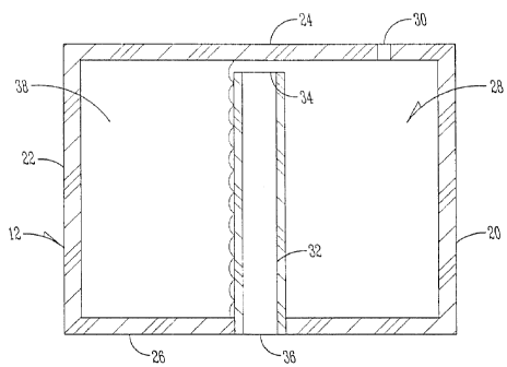
As best seen in Figures 3 and 4, the balance ring 12 is hollow, and
includes an inner wall 20, and outer wall 22, an upper wall 24, and a lower
wall 26. The walls 20, 22, 24 and 26 are sealed so as to define a cavity 28
therein.
The balance ring 12 includes an inlet opening 30 in the upper wall 24
thereof which permits water to be introduced into the cavity 28 during the
fill portion of the washing machine cycle of operations. In a first
embodiment, the balance ring 12 includes a plurality of standpipes or tubes
3


CA 02349392 2001-05-31
32 extending vertically within the cavity 28. The standpipes 32 include an
open upper end 34 spaced apart from the upper wall 24, and an open lower
end 36 which extends through the lower wall 26 of the balance ring 12. The
standpipes 32 function as drains, with the lower ends 36 thereof being in
communication with the interior of the tub 10.
In operation, the balance ring 12 is substantially filled with water 3 8
during the fill cycle of the tub 10, to a level reaching the upper ends 34 of
the standpipes 32 as shown in Figure 3. When the spin cycle for the tub 10
begins, the mass of the balance ring 12 assists in getting the rotating tub 10
through the critical speed with smaller deflections. As the rotational speed
increases, the centrifugal force forces the water 38 toward the outer wall 22
of the balance ring 12, such that the water 38 flows into the upper ends 34
of the standpipes 32 for drainage out the lower ends 36 of the standpipes 32.
When rotating tub 10 exceeds the critical speed, approximately 1/2 the
water 38 has been drained from the balance ring 12, as shown in Figure 4.
The remaining water 3 8 is free to flow to a balance position within the
balance ring 12 so as to counterbalance unbalanced loads in the tub 10.
In an alternative embodiment shown in Figure 5, the standpipes 32
are replaced with at least one drain opening 40 in the upper wall 24 of the
balance ring 12a. The balance ring 12a functions similarly to the balance
ring 12 shown in Figures 3 and 4, with the water 3 8 draining through the
drain openings) 40 when the tub 10 is raanping up to the critical speed, and
the remaining water being free to flow within the cavity 28 to a balance
position counter-acting any uneven load in the tub 10.
2 s In the drawings and specification there has been set forth a preferred
embodiment of the invention, and although specific terms are employed,
these are used in a generic and descriptive sense only and not for purposes
4


CA 02349392 2001-05-31
of limitation. Changes in the form and the proportion of parts as well as in
the substitution of equivalents are contemplated as circumstances may
suggest or render expedient without departing from the spirit or scope of the
invention as further defined in the following claims.

Representative Drawing
A single figure which represents the drawing illustrating the invention.
Administrative Status

For a clearer understanding of the status of the application/patent presented on this page, the site Disclaimer , as well as the definitions for Patent , Administrative Status , Maintenance Fee  and Payment History  should be consulted.

Administrative Status

Title Date
Forecasted Issue Date 2006-07-11
(22) Filed 2001-05-31
(41) Open to Public Inspection 2002-03-06
Examination Requested 2003-05-29
(45) Issued 2006-07-11
Deemed Expired 2010-05-31

Abandonment History

There is no abandonment history.

Payment History

Fee Type Anniversary Year Due Date Amount Paid Paid Date
Registration of a document - section 124 $100.00 2001-05-31
Application Fee $300.00 2001-05-31
Maintenance Fee - Application - New Act 2 2003-06-02 $100.00 2003-02-03
Request for Examination $400.00 2003-05-29
Maintenance Fee - Application - New Act 3 2004-05-31 $100.00 2004-01-13
Maintenance Fee - Application - New Act 4 2005-05-31 $100.00 2005-02-03
Maintenance Fee - Application - New Act 5 2006-05-31 $200.00 2006-01-24
Final Fee $300.00 2006-05-01
Maintenance Fee - Patent - New Act 6 2007-05-31 $200.00 2007-04-30
Maintenance Fee - Patent - New Act 7 2008-06-02 $200.00 2008-04-30
Owners on Record

Note: Records showing the ownership history in alphabetical order.

Current Owners on Record
MAYTAG CORPORATION
Past Owners on Record
SEARS, JEFFREY L.
Past Owners that do not appear in the "Owners on Record" listing will appear in other documentation within the application.
Documents

To view selected files, please enter reCAPTCHA code :


To view images, click a link in the Document Description column. To download the documents, select one or more checkboxes in the first column and then click the "Download Selected in PDF format (Zip Archive)" or the "Download Selected as Single PDF" button.

List of published and non-published patent-specific documents on the CPD .

If you have any difficulty accessing content, you can call the Client Service Centre at 1-866-997-1936 or send them an e-mail at CIPO Client Service Centre.


Document
Description 
Date
(yyyy-mm-dd) 
Number of pages   Size of Image (KB) 
Representative Drawing 2002-01-21 1 9
Description 2003-08-22 5 185
Claims 2003-08-22 3 74
Abstract 2001-05-31 1 28
Description 2001-05-31 5 187
Claims 2001-05-31 3 82
Drawings 2001-05-31 4 61
Representative Drawing 2006-06-14 1 10
Cover Page 2006-06-14 1 41
Cover Page 2002-03-01 1 40
Correspondence 2006-05-01 1 31
Assignment 2001-05-31 5 230
Prosecution-Amendment 2003-05-29 1 28
Prosecution-Amendment 2003-08-22 6 156