Note: Descriptions are shown in the official language in which they were submitted.
CA 02349625 2001-05-31
LATCHING MECHANISM FOR AN APPLIANCE DOOR
BACKGROUND OF THE INVENTION
Field of the Invention
The present invention pertains to the art of <~ppliances and, more
particularly, to a latching mechanism for the door of an appliance.
Discussion of the Prior Art
The desire to latch an access door of an appliance in a closed position
for various reasons is recognized in the art. Particularly, it is often
desired
to assure the positive latching of an appliance door during certain operating
modes for safety reasons, as well as to enable the avppliance to operate
properly. For instance, the need for an access door latching arrangement is
particularly realized in dishwashing machines. That is, as the machine
proceeds through a washing operation, there is a need to maintain a proper
seal about the periphery of the access door in order to assure that water,
which is sprayed throughout the interior of the dishwasher in various stages
of an overall washing operation, does not leak abort the access door.
Therefore, although a sealing gasket may be provided about the access door,
it is necessary to maintain the door in a proper position and to latch the
door
to maintain the desired sealing.
Of course, the need to incorporate a latching mechanism in an
appliance adds to the associated manufacturing co;>ts. In addition, the
latching mechanism can introduce certain design constraints and
considerations. For example, given the life expentancy of a typical
household appliance, the latching mechanism musl: be effectively designed
for reliable operation over a prolonged period of time. Therefore, the
mechanism must accommodate manufacturing tolerances and possible
CA 02349625 2001-05-31
relative shifting between the access door and the remainder of the appliance
over its useful life in order to avoid the need for independent adjusting of
the latching mechanism for proper operation:
In latching mechanisms for certain appliances, it has heretofore been
proposed to electrically signal when a latched condition has been reached,
with the signal being received by a control unit which regulates other stages
of operation for the appliance. For example, as indicated above, it would
not be desirable to initiate a dishwashing operation until it was assured that
the access door for the dishwasher was fully latched. However, when
utilizing an electrical switch in connection with thf; latching mechanism for
an appliance, there can arise certain timing considerations. That is, it would
be beneficial to assure that an appropriate electrical signal is forwarded to
the controls for the dishwasher upon an initial stage of unlatching of the
appliance door rather than simultaneously with the reaching of an unlatched
condition. In any event, although various latching mechanisms for
dishwashers and other appliances have already been proposed in the art, in
general, these known arrangements are considered to have certain
shortcomings such that a need exists in the art for an improved mechanism
for reliably latching the access door of an appliance, as well as providing
for
an improved timing arrangement when electrically signaling the latching
status of the mechanism to a control unit of the appliance.
SUMMARY OF THE INVENTION
The present invention is directed to a mechanism particularly adapted
for use in latching a pivotal access door of an appliance in a closed position
during predetermined modes of operation of the appliance. The latching
mechanism incorporates structure for releasably retaining the door in a
2
CA 02349625 2003-08-22
closed position, as well as additional structure for electrically signaling
the
latching state of the mechanism to a control unit of the appliance in a timed
manner.
The invention in one broad aspect pertains to a cabinet provided with an
access opening and a pivotable door adapted to extend across and close the
access
opening. A mechanism is provided for latching the pivotable door in a closed
position comprising a latch housing mounted to one of the door and the
cabinet, the
latch housing including an opening therein, wherein the opening in the latch
housing includes a beveled portion about a periphery thereof. A catch member
is
movably mounted relative to the latch housing between latching and receiving
positions. A striker element is mounted to one of the door and the cabinet,
the
striker element being guid~l by the beveled portion into the opening of the
latch
housing to abut the catch member and cause shifting of the catch member from
the
receiving position to the latching position upon closing the door.
The invention also provides broadly a method of latching a pivotable access
door in a closed position comprising causing a striker member to engage and
rotate
a catch member about a first axis defined within a latch housing, and shifting
the
catch member relative to the latch housing about a second axis, which is
spaced
from the first axis, in order to retain the striker member within the latch
housing.
3
CA 02349625 2003-08-22
In accordance with a preferred embodiment of the invention, the
latching mechanism includes a latch housing within which is rotatably
mounted a catch member. The catch member is actually rotatably supported
between latching and unlatching positions upon a latch bracket or carrier
which, in turn, is pivotably supported in the latch housing. The carrier is
biased, preferably by a pair of laterally spaced springs, into engagement
with a cam pin or rod which acts as a pivot stop for the carrier. In
accordance with a first embodiment of the invention, a cross pin is
connected to the earner and rotatably supports a latch handle having one
end portion which is adapted to engage the carrier for rotating the same
against the biasing force of the springs. The cross pin actually extends
through a pair of laterally spaced slots formed in the latch housing such that
terminal ends of the cross pin are exposed. Electronic switches are arranged
adjacent the terminal ends of the cross pin and are adapted to be depressed
when the latching mechanism assumes a latched condition. A spring is also
provided to bias the handle towards a non-engagement position with the
carrier.
The catch member itself is formed with a caroming surface defining
at least first and second radially spaced detent positions adapted to be
engaged by the cam pin depending upon whether the latching mechanism is
in a latched or unlatched state. More specifically, when the overall latching
mechanism is in an unlatched state, the catch member is located in a
position wherein the carrier is depressed and the cam pin is received in the
first detent in order to maintain the catch member in a desired receiving
3A
CA 02349625 2001-05-31
position for a latch striker. That is, the catch member includes first and
second spaced arms that define a receiving area therebetween which is
aligned with an opening provided in a rear portion of the latch housing for
receiving the latch striker. In this unlatched condition, the earner is spring
loaded and the cross pin is shifted to a position wherein the electric
switches
are not engaged. When the latch striker enters between the arms of the
catch member, the catch member is forced to rotate which causes the cam
pin to come out of engagement with the first detent , ride along the caroming
surface and become positioned at the second, latching detent. In the
latching position, the carrier is shifted relative to the housing and, in
turn,
the cross pin is shifted within the receiving slots of the housing to engage
the electrical switches. With the switches engaged., a signal is provided to
verify that the mechanism is properly latched.
In a second prefered embodiment of the invention, the latch handle is
replaced by a shortened handle which, instead of pivoting about an axis
defined by the cross pin, it is rotatably supported directly by the latch
housing. In this embodiment, the handle is providc;d with two proj ecting
prongs which directly abut the carrier for pivoting of the earner and shifting
of the cross pin against the biasing force of the latch springs. This second
embodiment also has a modified form wherein the handle is completely
removed. In this modified form, the latching mech<~nism is shifted from an
unlatched condition to a latched condition by simply pushing on the
appliance door such that the latch striker causes the catch member to
automatically rotate. In order to unlatch the overall assembly, the appliance
door is pulled by a force which causes the carrier to deflect against the
biasing force of the springs, with a corresponding rotation of the catch
member. In each of the embodiments, the carrier is rotated about an axis
4
CA 02349625 2003-08-22
defined by a reinforcing rib of the housing to cause the cross pin to activate
the electronic switches. Mounting the cross pin in slots enables an
appropriate timing between the signals sent from the switches to a control
unit of the appliance and the actual latching state change of the overall
mechanism.
Additional aspects, features and advantages of the present invention will
become more readily apparent from the following detailed description of the
preferred embodiments thereof, when taken in conjunction with the drawings
wherein like reference numerals refer to corresponding parts in the several
vie;vs.
BRIEF DESCRIPTION OF THE DRAWINGS
Figure 1 is a front perspective view of a dishwashing machine
incorporating the latching mechanism of the present invention;
Figure 2 is a perspective view of the latching mechanism of the
present invention constructed in accordance with a first preferred
embodiment;
Figure 3 is a front plan view of the latching mechanism of Figure 2,
with portions of the handle removed for clarity purposes;
Figure 4 is a side view of the latching mechanism of Figure 2 in a
latched state;
Figure S is a side view, similar to that of Figure 4, with the handle of
the latching mechanism being shifted to an initial state during an unlatching
operation;
Figure 6 is a side view, similar to Figures 4 and S, depicting the
latching mechanism in an unlatched condition;
CA 02349625 2001-05-31
Figure 7 is a rear plan view of the latching mechanism of Figures 2-
6;
Figure 8 is an exploded, perspective view of a second embodiment of
the latching mechanism of the present invention;
Figure 9 is a front view of the latching mechanism of Figure 8
without the handle of Figure 8; and
Figure 10 is a side view of the latching mechanism according to the
second embodiment of the invention in an unlatched condition.
DETAILED DESCRIPTION OF THE PREFERRED EMBODIMENTS
With initial reference to Figure 1, a dishwasher 2 is generally
indicated to be positioned below a kitchen countertop 5. Also below
countertop 5 is shown cabinetry 8 including a pair of drawers 10 and 11 and
lower cabinet doors 13 and 14. Dishwasher 2 includes a door 17 that is
pivotally mounted to a cabinet shell 19. Dishwasher 2 is also shown to
include an access panel 21 and a control panel portion 24. Control panel
portion 24 includes a display 27, a row of control buttons 29 and a vent zone
33. In general, this overall arrangement of dishwasher 2 and countertop 5 is
known in the art wherein dishwasher door 17 is adapted to extend across
and close an access opening associated with cabinet shell 19, while also
being pivotable, such as through handle 36, to a position which enables
loading and unloading of dishwasher 2. Since this general construction and
operation of dishwasher 2 is widely known in the art, it will not be
discussed further here in detail. Instead, the present invention is
particularly
directed to a latching mechanism for dishwasher door 17, a first preferred
embodiment thereof being illustrated in Figures 2-~i.
6
CA 02349625 2001-05-31
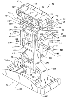
As shown in the embodiment of Figures 2- i', a latching mechanism
42 includes a latch housing 45 that is preferably, ir.~tegrally molded of
plastic. Latch housing 45 includes an upper panel 48, side panels 49 and 50,
a back panel 51 and a generally central, upstanding cross rib 52 extending
between side panels 49 and 50. Each side panel 49, 50 includes an upper
section 56 and a lower section 57 which are interconnected by a respective
laterally extending section 58. Extending laterally outwardly from upper
section 56, adjacent back panel 51, is a pair of flanges 62 and 63, each of
which includes a respective aperture 65. At lower section 57 is formed an
upstanding mounting projection 68 which is also provided with an aperture
69. Flanges 62 and 63, along with upstanding mounting projection 68, are
adapted to receive mechanical fasteners, such as screws, for mounting latch
housing 45 within dishwasher door 17.
Along laterally extending section 58 of side panels 49 and 50 are
formed a pair of laterally spaced mounting bosses '72 and 73. Bosses 72 and
73 have respective, aligned bores 74 and 75 that define an axis which
extends laterally across housing 45. Generally adjacent mounting bosses 72
and 73, latch housing 45 is preferably formed with recessed areas 78 and 79
for reasons which will become more fully evident below. In addition, latch
housing 45 is preferably formed with a pair of slots 82 and 83, each in a
respective lower section 57 of side panels 49 and 50. Also formed at lower
section 57 of each side panel 49 and 50 are a pair o~f laterally outwardly
projecting posts 87 and 88, as well as clip members 90 and 91. In back
panel 51 of latch housing 45, preferably slightly below upper panel 48, is
formed a receiving slot 94 which, in the most preferred form of the
invention, has its entire periphery beveled or tapered at back panel 51 as
indicated at 96 (see, particularly, Figure 7).
7
CA 02349625 2001-05-31
Latching mechanism 42 further incorporate;s a catch member or cam
104 including a sleeve 107 from which projects an arcuate extension 110
that defines a caroming surface 112. Along camm.ing surface 112 is defined
first and second detents 114 and 115. Catch memlber 104 also has
proj ecting from sleeve 107, generally opposite arcuate extension 110, a pair
of spaced arms 117 and 118. Within sleeve 107 is provided an internal
spring 120 having terminal legs 122 and 123 (see lFigure 3). As will be
detailed more fully below, spring 120 biases catch member 104 into a
receiving position.
Latching mechanism 42 also includes a cannier or latch bracket 128
that is preferably formed of metal. As shown, carrier 128 is generally in the
form of an inverted U and includes elongated side portions 131 and 132,
each of which is preferably, generally L-shaped in cross-section so as to
include a frontal extension 134 and a side extension 135. Carner 128 also
includes an upper cross piece 137, as well as a reinforcing second cross
piece 138. Adjacent upper panel 48, earner 128 includes a pair of tabs 140,
141 which project from frontal extension 134 of each side portion 13 l and
132. Tabs 140 and 141 are provided with respective through holes 144 and
145. On the other hand, each side extension 135 is formed with a respective
cross hole 148 and 149 which are aligned along a laterally extending axis.
As will be detailed more fully below, tabs 140 and 141 are adapted to be
biased by means of respective springs 153 away from back panel 51 of latch
housing 45.
As shown in these figures, catch member 104 is rotatably mounted
between side extensions 135 of elongated side portions 13 l and 132 of
carrier 128, with carrier 128 and catch member 104. being positioned within
latch housing 45. More specifically, tabs 140 and 141 are arranged at upper
8
CA 02349625 2001-05-31
section 56 of side panels 49 and 50 respectively, while side portions 131 and
132 of carrier 128 project along lower sections 57 of side panels 49 and 50.
Each spring 153 abuts both back panel 51 and a respective tab 140 and 151.
Latching mechanism 42 further includes a cam pin or rod 157 which
extends through aligned bores 74 and 75 of mounting bosses 72 and 73, as
well as a earner or cross pin 161 which extends through each of slots 82 and
83, as well as cross holes 148 and 149. In this ma~:mer, carrier 128 is
interconnected to latch housing 45 through cross pin 161, with upstanding
rib 52 of latch housing 45 acting as a fulcrum upon which cross piece 138 of
carrier 128 is positioned. On the other hand, catch member 104 shifts in
unison with earner 128 about cross pin 161 while ;also being rotatable
relative to carrier 128 by means of a pin 162 (see Figure 4) which extends
through sleeve 107 and the side extension 135 of each side portion 131 and
132. As shown, cross pin 161 preferably has terminal end portions 163 and
164 which project laterally outwardly of side panels 49 and 50 for the
reasons which will be more fully discussed below. In addition, cross pin
161 preferably includes a reduced diametric portion 165 that is shown to be
centered along the length of cross pin 161. In the most preferred form, both
cam pin 157 and cross pin 161 axe formed of metal.
In accordance with this embodiment, handle; 36 includes a body
portion 168 that is preferably integrally molded of ;plastic. Body portion
168 includes side portions 170 and 171, as well as 'various reinforcing cross
ribs 173-176. Body portion 168 is also formed witlh a pair of grip receiving
mounts 180 and 181. Handle 36 also includes a grip 183 that is preferably
formed separate from body portion 168 and includes posts 186 and 187
which are received within mounts 180 and 181 and secured therein,
preferably by the use of threaded fasteners (not shown). Side portions 170
9
CA 02349625 2001-05-31
and 171 of handle 36 are preferably formed with curved upper ends 190 and
191 which are adapted to abut the frontal extension 134 of side portions 131
and 132 of carrier 128 during an unlatching sequence, as will be described
more fully below. Body portion 168 is also formed with a pair of pivot
extensions 195 and 196 which have respective aligned bores 198 through
which cross pin 161 extends. Therefore, both carrier 128 and handle 36 are
attached to latch housing 45 through cross pin 161. Finally, handle 36 is
shown to include a guide projection 201 (see Figure 3) which has an end
terminating within reduced diametric portion 165 of cross pin 161.
The overall latching mechanism 42 also preferably includes a pair of
electrical switches 208 and 209. Each electrical svvitch 208, 209 icludes a
body 21 l, a pair of electrical connectors 213, 214 and an activation member
216 (see Figure 6). In general, when activation member 216 is depressed,
connectors 213 and 214 are electrically interconnected. The body 211 of
each switch 208 and 209 is provided with a pair of bores 219 and 220.
As indicated above, catch member 104 is biased by spring 120 to an
unlatched or receiving position as best shown in Figure 6. In the most
preferred embodiment, side portion 131 of carrier l~ 28 has lanced out a tab
223 against which leg 122 of spring 120 abuts. The second leg 123 of
spring 120 terminates within catch member 104 as shown in Figure 3. In
any event, spring 120 biases catch member 104 from the position shown in
Figure 4 towards the position shown in Figure 6. As also indicated above,
catch member 104 is shifted in unison with the pivoting or rocking of earner
128 upon upstanding rib 52, while handle 36 pivots about cross pin 161. A
spring 225 has a first end 228 which is attached to a cross support 221
formed as part of back panel 51 and a second end 233 which s looped about
a protrusion 235 formed as part of body portion 168. Therefore, spring 225
CA 02349625 2001-05-31
biases handle 36 to a non-use position as best shown in Figure 4. In this
position, the curved upper ends 190 and 191 of body portion 168 are spaced
from elongated side portions 131 and 132 of carnf;r 128.
Figures 2-5 depict latching mechanism 42 in a latched condition.
That is, a latch striker 240, which includes a mounting portion 242, adapted
to be attached to cabinet shell 19, and a latch portion 244 provided with an
opening 246, is used in combination with the othen~ components of latching
mechanism 42 carried by latch housing 45 to selectively latch dishwasher
door 17 across the frontal opening of cabinet shell 19. More specifically,
when latching mechanism 42 is in a latched condition, latching portion 244
of latch striker 240 extends through receiving slot 94 formed in back panel
51 and between arms 117 and 118 of catch member 104. Closing of
dishwasher door 17 will force catch member 104 to rotate relative to carrier
member 128 by direct abutment of latching portion 244 with arm 117.
Catch member 104 will rotate about pin 162, with cam pin 157 riding along
caroming surface 112 until cam pin 157 reaches second detent 115. Given
that detent 115 is radially spaced from caroming surface 112, springs 153
will force, indirectly through carrier 128, catch member 104 to shift away
from back panel 51. The rotation of catch member 104 tends to load
internal spring 120 which, as indicated above, bias ~s catch member 104 to
the position shown in Figure 6. When springs 153 shift Garner 128, side
portions 131 and 132 of Garner 128 abut cam pin 157 which, in turn, forces
cross pin 161 to be shifted within slots 82 and 83. Arranged directly at the
lower ends of slots 82 and 83 are the activation members 126 of the
electrical switches 208 and 209 which, in turn, are :mounted with posts 87
and 88 extending through bores 219 and 220 and clips 90 and 91 projecting
around respective portions of body 211 as clearly shown in these figures.
11
CA 02349625 2001-05-31
Therefore, in this latched condition, terminal end portions 163 and 164 of
cross pin 161 are forced into abutment with the activation members 216 of
electrical switches 208 and 209 respectively in order to electrically link
connectors 213 and 214. Electrical switches 208 wind 209 are wired to a
controller (not shown) in panel 24 and function to send signals regarding the
latching state of mechanism 42. Since latch striker 240 is retained by catch
member 104 prior to the shifting of cross pin 161, there is an inherent time
delay in the signaling of the latching state. The significance of this time
delay will be discussed further herein.
When it is desired to unlatch mechanism 42, handle 36 is initially
shifted from the position shown in Figure 4 to the position shown in Figure
5 about the pivot axis defined by cross pin 161. In the Figure 5 position,
curved upper ends 190 and 191 are initially brought into abutment with
elongated side portions 131 and 132 of carrier 128. Upon further lifting of
handle 36 at grip 183, handle 36 will tend to cause carrier 128 to pivot or
rock upon upstanding rib 52 such that cross pin 161 will be initially shifted
within slots 82 and 83 relative to latch housing 45. As cross pin 161 is
shifted within slots 82 and 83, cross pin 161 will be caused to become
disengaged from the activation members 216 of electrical switches 208 and
209. Thereafter, cross pin 161 will reach the ends of slots 82 and 83 and
abut portions of side panels 49 and 50 Thereafter, rthe further pulling of
grip
183 will cause handle 36 to pivot about cross pin 161 to cause upper ends
190 and 191 to push upon side portions 131 and 132 of carrier 128. Carrier
128 will be forced to pivot upon upstanding rib 52, initially disengaging
elongated side portions 131 and 132 from cam pin 157 and also causing
catch member 104 to shift towards back panel 51 relative to cam pin 157.
12
CA 02349625 2001-05-31
Once cam pin 157 reaches the height of cannming surace 112, catch
member 104 will automatically rotate due to the biasing of spring 120 until
cam pin 157 becomes positioned in the first detent 114 as shown in Figure
6. In this position, latch striker 240 is released from between arms 117 and
118 of catch member 104 such that dishwasher door 17 is free to pivot
relative to cabinet shell 19. Although springs 153 tend to bias carrier 128 to
the position shown in Figures 2-5, carrier 128 is prevented from pivoting
and cross pin 161 is maintained spaced from activation members 216 of
electrical switches 208 and 209 due to the presencf; of upstanding rib 52 and
the arrangement of cam pin 157 in first detent 114. Therefore, without the
rotation of catch member 104, latching mechanism. 42 will remain in the
unlatched state of Figure 6, although handle 36 would actually,
automatically shift to the position shown in Figure 4 due to the biasing force
created by spring 225.
As with the latching sequence, the unlatching of mechanism 42 has
an associated inherent timing sequence with the signals sent from electrical
switches 208 and 209. That is, a latching signal from switches 208 and 209
is terminated by the shifting of cross pin 161 away from activation members
216 during an initial unlatching stage. When latching mechanism 42 is
incorporated in an appliance such as dishwasher 2, this timing sequence is
considered to be important since, if a consumer attE;mpts to open dishwasher
door 17 during a wash cycle, the controls for dishwasher 2 will receive an
early indication and will have ample time to terminate the operation of any
sprayers, motors, pumps and the like. In addition, when shifting between
the unlatched and latched positions, dishwasher door 17 becomes fully
latched prior to the closure of switches 208 and 209 such that this
configuration also provides an advantageous time f.elay. It should also be
13
CA 02349625 2001-05-31
noted that tapered or beveled periphery 96 of slot !a4 advantageously
functions to align latch striker 240 and receiving slot 94 even given possible
relative shifting between door 17 and cabinet shell 19 due to manufacturing
tolerances, as well as over the useful life of dishwasher 2.
Reference will now be made to Figures 8-1~0 in describing additional
preferred embodiments of the present invention. I:n general, the latching
mechanisms of these embodiments function in a manner substantially
identical to that described above with respect to the embodiment of Figures
2-7. Therefore, emphasis will be placed here on the differences between
these embodiments and it is to be understood that like reference numerals
refer to corresponding components between the various embodiments, with
these components performing the functions described above unless
otherwise detailed below.
In general, the latching mechanism 42' of Figures 8-10 is more
compact than the latching mechanism of Figures 2-7. Latching mechanism
42' includes a latch housing 45' which is shortened as compared to latch
housing 45 and does not include a corresponding upstanding mounting
projection 68, but rather simply has a lower end wall 253. As also clearly
shown in these figures, the elongated handle 3 6 and its corresponding guide
projection 201 is not present. To perform corresponding functions, latch
housing 45' includes a center extension 256 which projects from back panel
51'. Center extension 256 preferably includes a bifurcated end 258 which is
positioned within reduced diametric portion 165 of cross pin 161 and which
receives second end 233 of spring 225 which extends around cross pin 161.
Therefore, in this embodiment, spring 225 biases cross pin 161 towards the
activation members 216 for electrical connectors 211.3 and 214. It should be
noted that the construction, interconnection and function of catch member
14
CA 02349625 2001-05-31
104, carrier 128, latch springs 153, cam pin 157, cross pin 161 and electrical
switches 208 and 209 are the same as that of the first embodiment described
above.
The latching mechanism 42' of Figures 8-10 can be used with or
without a handle 263. As shown, handle 263 includes a face portion 264
having an associated undercut 265 for use in gripping handle 263. Handle
263 also includes a first pair of laterally spaced extensions 266 and 267,
each of which is supported by perpendicular reinforcing ribs 268 and 269.
Each laterally spaced extension 266, 267 has associated therewith a
respective, laterally inwardly extending stub shaft 271, 272, at least one of
which preferably has a tapered end portion 273. Furthermore, handle 263
has associated therewith a pair of projections or prongs 274 and 275, with
this structure being clearly shown in Figures 8 and 10.
With this arrangement, stub shafts 271 and 272 are adapted to be
positioned within recessed areas 78 and 79 respectively. With at least one
of stub shafts 271 and 272, including the tapered end portion 273, the initial
positioning of one stub shaft 271, 272 in a respective recessed area 78, 79
will enable the other stub shaft 272, 271 to be snap-fit into its respective
recessed area 79, 78 with the aid of the tapered end. portion 273. In any
event, handle 263 will be able to pivot about an axis defined by stub shafts
271 and 272. When latching mechanism 42' is in an unlatched state,
projections 274 and 275 are spaced from elongated side portions 131 and
132 of carrier 128. However, after latch striker 240 is received between
arms 117 and 118 to cause rotation of catch member 104 upon closing of
dishwasher door 17, the subsequent pivoting of cancer 128 and the shifting
of cross pin 161 in slots 82 and 83, projections 274 and 275 preferably abut
side portions 131 and 132. That is, in the arrangement shown in Figure 10,
CA 02349625 2001-05-31
handle 263 is free to pivot from the position shown, wherein projections 274
and 275 abut carrier 128, counterclockwise until a rear portion 280 of
handle 263 abuts latch housing 45'. However, whE;n latching mechanism 42'
is latched, projections 274 and 275 directly abut courier 128. In any event,
when in this latched condition, the lifting of handle 263 causes handle 263
to pivot about the axis defined by stub shafts 271 wind 272 whereupon
projections 274 and 275 directly deflect carrier 128 thereby causing the
shifting of crass pin 161 away from electrical connectors 213 and 214 and,
subsequently, the rotation of catch member 104 through the biasing of
spring 120 and the release of latch striker 240.
At this point, it should be noted that Figures 8-10 can actually
represent another embodiment of the invention wherein no handle at all is
utilized. That is, handle 263 is not a required component. Instead, latching
mechanism 42' can assume a latching position upon closing of dishwasher
door 17 with latching portion 244 of latch striker 240 causing the rotation of
catch member 104 and the shifting of earner 128, as well as cross pin 161.
The unlatched state would require a tug on dishwa;>her door 17 whereupon
latch striker 240 would be drawn from rear receiving slot 94 while acting on
arm 118 of catch member 104 to cause catch member 104 to both deflect
away from cam pin 157 and rotate relative to carne;r 128 until cam pin 157
was received in second detent 115. In fact, the first embodiment of Figures
2-6 could also operate in a corresponding manner if desired.
Based on the above, it should be recognized that the various
components of the latching mechanism 42, 42' of the present invention are
interconnected in such a manner so as to produce synergistic results,
including the timing of electrical signals to a controller for dishwasher 2
concerning the latching status of the overall mechaanism 42, 42'. Although
16
CA 02349625 2001-05-31
described with respect to preferred embodiments of the invention, it should
be readily understood that various changes and/or modifications can be
made to the invention without departing from the spirit thereof. For
example, although the latching mechanism 42, 42" has been disclosed in
connection with dishwasher 2, mechanism 42, 42' could be utilized on
various types of appliances or even other cabinet ;>tructure as well. In any
event, the invention is only intended to be limited by the scope of the
following claims.
17