Note: Descriptions are shown in the official language in which they were submitted.
CA 02349736 2001-06-06
1
°. "Foldaway lifting device for disabled people in wheelchairs
and children's pushchairs"
***
Background of the invention
This invention relates in general to equipment for
facilitating the access of disabled people and children's
pushchairs aboard motor vehicles, i.e. public transport
vehicles, or more simply to fixed installations, such as
public buildings, museums and similar.
Specifically, this invention relates to a lifting
device for disabled people in wheelchairs, intended to be
permanently applied to a vehicle or to a fixed
installation, to overcome the difference in level between a
lower station and an upper station, for accessing said
vehicle or said fixed installation.
Summary of the invention
The purpose of this invention is to provide a lifting
device of this type which can be fully folded away, i.e.
which is included in the volume of the vehicle, or of the
fixed installation, to which it is applied, until its use
is required.
An additional purpose of this invention is to provide
a particularly functional foldaway lifting device, which
conformation is relatively simple and cost-effective, and
which does not employ fluid actuators.
According to this invention, this purpose is obtained
essentially thanks to the fact that the lifting device
comprises:
CA 02349736 2001-06-06
2
- a supporting frame embedded within a housing
provided under said upper station of the vehicle or
fixed installation,
- a sliding foldaway platform, moving between a
retracted position and an extracted position, with
respect to said supporting frame, and also moving,
in said extracted position, between a lowered
condition, in which it rests on said lower station,
and a raised condition, in which it is
substantially arranged on the level of said upper
station,
- articulated parallelogram linkage means between
said platform and said frame, and
- electrical actuator control means for moving said
platform between said retracted position and said
extracted position and, by means of said
articulated parallelogram linkage means, between
said lowered condition and said raised condition.
According to a preferred embodiment of this invention,
said platform is conveniently equipped with a front board,
moving between an erected position and a folded position,
in which is acts as a front slide for accessing said lower
station. Furthermore, the platform can be equipped with a
rear extractable extension, sliding over the platform
between a retracted position and an extracted position, in
which it acts as a rear slide for connecting to the upper
station. Electrical actuator means for controlling the
movements of said front board and said sliding extension
are provided.
The lifting device according to this invention can be
advantageously equipped with a remote control device, or
CA 02349736 2001-06-06
3
magnetic card, or similar, operatively associated to the
respective control device for allowing also remote
activation by the user.
Brief description of the drawings
This invention will be better explained by the
following detailed descriptions with reference to the
accompanying figure as non-limiting example, wherein:
- figure 1 is a perspective schematic view shows an
example of application of the lifting device
according to this invention on a bus, where the
lifting device is shown in an inoperative,
retracted position,
- figure 2 is a perspective view on a larger scale of
the lifting device in the retracted position of
figure 1,
- figure 3 is a similar view to figure 1 with the
lifting device in extracted position,
- figure 4 is a similar view to that of figure 2
showing the lifting device in the extracted
position of figure 3,
- figure 5 is a similar view to figure 1 with the
lifting device in lowered position,
- figure 6 is a similar view to figure 2 showing the
lifting device in the lower condition of figure 5,
- figure 7 is a similar view to figure 1 showing the
lifting device in lifted position with the rear
extension in extracted position,
- figure 8 is a similar view to figure 2 showing the
lifting device in the lifting condition in figure
7,
- figure 9 is a perspective partial view on an
CA 02349736 2001-06-06
4
exploded, larger scale of a detail of the platform
of the lifting device, and
- figures 10 and 11 are perspective and scaled down
views of two variants of the lifting device
according to this invention.
Detailed description of the invention
The example of embodiment of the invention illustrated
in the drawings refers to the application of the lifting
device according to this invention on a public transport
vehicle, for example a bus. It must be emphasised that the
following description, expressly referred to said example
of embodiment, is essentially identically applicable in the
case of the application of the lifting device according to
this invention to other types of vehicles, and also to
fixed installations.
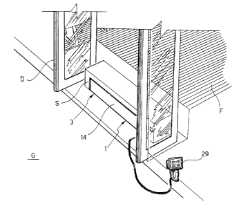
In the drawings, F refers to the floor of a bus
accessible from the outside across a door D and a set of
steps of which the intermediate step, located on a lower
level with respect to the floor F, is indicated with S.
This step S presents a hollow shape and is normally
closed (figures 1 and 2) by the front extremity of a
lifting device according to this invention, generally
indicated with numeral 1, permanently applied and folded
away inside the cavity of the step S.
With more detailed reference to figure 2, the lifting
device 1 essentially comprises a stationary supporting
frame 2 and a mobile platform; as explained below, with
respect to the supporting frame 2.
The supporting frame 2 is generally U-shaped with a
rear side 4 and to lateral sides 5 reciprocally connected
by two transversal profiles 6, which define two essentially
C-shaped longitudinal sliding guides 7. As better appears
CA 02349736 2001-06-06
in figures 4, 6 and 8, a first electrical geared motor 8,
operating a worm screw system 9, extending along one of the
lateral sides S and which function will be explained in the
following description, is fastened to the rear side 4 of
the supporting frame 2.
The mobile platform 3 includes two longitudinal sides
10, consisting of contoured profiles shown in detail in
figure 9, interconnected by a horizontal base 11 over which
a structural plate 12 can be arranged, for example
consisting of an embossed aluminium panel. The shape of the
sides 10 is complementary to that of the guides 7 in which
they slide. An enlargement 13 is arranged on a side 10 near
the front side of the platform 2.
This front side consists of a board 14, which is
articulated to the lower parts of the sides 10 of the
platform 3 so to rock between an erected position, shown in
figures 1-4 and 7, 8, and a folded position, shown in
figures 5 and 6, in which it extends essentially along the
extension of the base 11, acting as a front board 14. A
second electrical geared motor 15, housed inside the
enlargement 13, in the way shown in figure 9, and a worm
screw system 16 are provided to turn the front board 14
between the erected position and the folded position.
The lateral sides of the platform 3 are connected by
means of an articulated parallelogram linkage system formed
by two pairs of articulated longitudinal arms 17 and a
mobile unit, generally indicated with numeral 18, which
also slides with the platform 3 along the sides 5 of the
supporting frame 2. This mobile unit 18 essentially
comprises a crossbar 19, operatively connected to the worm
screw system 9, operated by the motor 8, which is connected
to a third electrical geared motor 20 arranged essentially
in central position. This geared motor operates two screw
CA 02349736 2001-06-06
6
jacks 21, arranged to multiply the torque of the motor 20,
meshing with the respective worm screws 22, connected to a
pair of respective connecting rods, or rocker arms, 23
fitted on the extremity of a transversal torsion bar 24.
Said transversal torsion bar 24 synchronises the movement
of the two connecting rods 23 for controlling the two
articulated parallelogram arms 17 so to obtain the
downwards rotation to the position illustrated in figures 5
and 6 and the upwards rotation to the position illustrated
in figures 7 and 8 from the horizontal configuration shown
in figures 1 to 4. A lowered position of the platform 3
corresponds to the downwards rotation related to the
supporting frame 2, while the upwards rotation corresponds
to a raised condition of said platform 3.
The rear side of the platform 3 consists of a board 25
mobile between a closed position, shown in figures 2-6, in
which it extends transversally with respect to the figures
7 and 8. This rear board 25 is actually formed by two pairs
of articulated elements 26, 27, the first of which pivots
on the rear extremities of the lateral sides 10 and the
second of which pivots on an extension 28 of the base 11 of
the platform 3. This extension 28 slides telescopically
with respect to the base 11 between a retracted position,
shown in figures 2 to 6, and an extracted position, shown
in figures 7 and 8, in which it acts as a rear slide for
the platform 3, according to the method illustrated below.
The movement of the sliding extension 28 between the
retracted and extended positions is also controlled by an
electrical geared motor, not illustrated in the drawings,
similar to the geared motor 15 described above related to
the worm screw system.
It must be emphasised that both the base 11 and the
extension 28 may be made of multiple elements forming the
CA 02349736 2001-06-06
respective extensible and retractable telescopic structures
instead of each being made of a single element. An
arrangement of this sort (schematically illustrated in
figure 10 according to the base 11 of the platform 3)
considerably reduces the volume of the lifting device 1.
The electrical actuators described above are connected
to a control unit, not illustrated in the drawings because
known by experts of the sector, for controlling the
operation according to a sequential phased cycle. For
controlling this cycle, the lifting device 1 according to
the invention is conveniently equipped with a remote
control unit, for example of the type indicated by numeral
29 in the drawings. This unit may consist of an equivalent
remote control device, also of the type employing a
magnetic card (as schematically shown in figure 11), radio-
frequency or infrared remote control, or similar.
The control logic of the lifting device 1 according to
this invention can acknowledge the presence of the disabled
person aboard. The system arranges and operates the devices
normally provided aboard vehicles for safely fastening the
wheelchair, which may also fold away to avoid hindrance and
obstacles to passengers when no disabled person is aboard.
The operation of the lifting device is described
below.
Normally, i.e. when its use is not required, the
lifting device 1 is completely folded away inside the step
S.
When a disabled person in a wheelchair requires use,
by means of the remote control 29 or similar control
device, firstly the geared motor 8 is activated which, via
the worm screw unit 9, makes unit 18 - and, consequently,
the platform 3 - slide with respect to the supporting frame
2 from the retracted position of figures 1 and 2 to the
CA 02349736 2001-06-06
8
extracted position of figures 3 and 4. In this way, the
platform 3 is folds out from inside the frame 2 and,
consequently, from the step S, with the arms 17 of the
articulated parallelogram systems horizontal, the front
board 14 erect and the rear board 25 closed.
From this position, the operation of the geared motor
20 causes the downwards rotation of the arms 17 in the
articulated parallelogram system, by means of the
connecting rods 23 and the torsion bar 24, to rest the
platform 2 on the ground, indicated with reference G, i.e.
on the disabled person's level. Having reached this
position (figures 5 and 6), the geared motor 15 controls,
via the worm screw system 16, the rotation of the front
board 14 from the raised position to the lowered position
shown in figures 5 and 6, so to form a slide or ramp
allowing comfortable access of the wheelchair on the
platform 3.
Consequently, the front board 14 is returned to the
lifted position, and the geared motor 20 is operated again
to the control the upwards rotation of the arms 17 of the
articulated parallelogram system, so to arrange the
platform 3 in the raised position shown in figures 7 and 8.
In this position, the platform 3 is arranged essentially on
the level of the floor F of the bus, or on a slightly
higher level. To allow the passage of the wheelchair from
the platform 3 to the floor F, the extension 28 is moved
from the retracted position to the extracted position,
illustrated in figures 7 and 8, in which it acts as a rear
slide connecting the platform 3 and the floor F. By effect
of this movement, the articulated elements 26, 27 of the
rear board 25 are distended, arranging essentially
longitudinally, as also shown in figures 7 and 8, so to
allow the passage of the wheelchair, doubling as lateral
CA 02349736 2001-06-06
9
guiding boards.
Finally, the platform 3 is returned, after the
extension 28 returns to the starting position, to the
retracted condition inside the supporting frame 2 and,
consequently, the step S.
Obviously, the disabled person will be lowered to the
ground level by reversing the sequence of operation
described above.
It appears obvious that the lifting device according
to this invention is extremely practical, functional and
relatively simple from the construction point of view,
considering that no hydraulic actuators and respective
service devices are implemented.
Naturally, numerous changes can be implemented to the
construction and forms of embodiment of the invention
herein envisaged, all comprised within the context of the
concept characterising this invention, as defined by the
following claims.
As mentioned above, the lifting device according to
this invention can be applied in an equally advantageous
way to any type of public transport vehicle, in addition to
fixed installations, such as museums, public buildings,
etc.