Note: Descriptions are shown in the official language in which they were submitted.
CA 02349824 2004-11-29
i
A METHOD OF MODELING THE
FORMING OF ANIS.OTROPIC SHEET
TECHNICAL FIELD
The present invention generally relates to the shaping of
deformable materials, and more particularly to a method of
forming metal sheet into useful articles, wherein tooling
is designed using mathematical models that rely on finite
element analysis (FEAR techniques to optimize forming
operations, tooling design and product performance in the
formed articles.
BACKGROUND ART
Many articles are made by stamping, pressing or punching a
base material so as to deform it into a piece or part '
having a useful shape and function. The present invention
is concerned with mathematical modeling of the mechanics
of such material flow and deformation, and is particularly
concerned with the deformation of metal (e. g., aluminum)
sheet using tools and dies, to produce a wide variety of
products, from beverage cans to components for automotive
applications.
When designing the shape of a product, such as a beverage
can, it is important to understand how the deformation
process will affect the blank of sheet metal. Finite
element analysis codes; available from a variety of
companies, can be used to analyze plasticity, flow and
deformation to optimize forming operations, tooling design
and product performance in product designs. These models
may result in tooling which improves the quality of a
product as well as reducing its cost. The predictive
capability of such finite element models is determined to
a large extent by the way in which the material behavior
is described therein.
CA 02349824 2001-05-08
WO 00/29918 PCT/CA99/01087
2
In order to appreciate the complexities of modeling the
deformation process, it is helpful to understand some
basic concepts of mechanical metallurgy, including the
concepts of yield stress, workhardening, and strain path.
5
When some type of external loading device, such as a
tensile test machine deforms a metal, the initial response
is elastic, with a linear relationship between stress and
strain. At some value of the stress, determined by the
10 microstructure of the metal, plastic deformation begins
and the response is non-linear, and comprises elastic plus
plastic deformation. The yield stress defines the
strength of the metal at the condition where plastic
deformation is initiated.
15
Deformation beycnd the yield stress is characterized by
workhardening which causes the stress to increase at an
ever decreasing rate until a failure mechanism intervenes
and the sample breaks. Thus, the yield stress value and
20 the workhardening curve are the two fundamental entities
that define the plastic deformation of metals.
The forming of metal sheet into industrial or consumer
products (e. g., cans and automotive components) occurs
25 under multi-axial straining conditions, not the simple
uniaxial path described above (tensile testing). In such
cases the deformation is described by the strain path.
The strain path is defined by the plastic strain tensor.
30 A tensor is a mathematical entity that is useful in
describing various physical properties. Most physical
properties can be expressed as either a scalar, a vector,
or a tensor.
CA 02349824 2001-05-08
WO 00/29918 PCT/CA99/01087
3
A scalar quantity is one which can be specified with a
single number (e. g., temperature or mass), while a vector
quantity is one which requires two values, such as
magnitude and direction (e. g., velocity or force).
5
A tensor quantity is a higher-order entity that requires
more than two values, i.e., more than a single magnitude
and direction. For example, a stress tensor is a 3x3
array, each term of which is defined by the stress acting
10 on a given plane, in a given direction. As two direction
cosines are required for transformations, the stress
tensor is a second order tensor.
The plastic strain (or strain rate) tensor is a second
15 order tensor, which~can be expressed as a 3x3 matrix and,
in principal axes, has the form:
a 0 0
20 0 b 0
0 0 c
CA 02349824 2001-05-08
WO 00/29918 PCT/CA99/01087
4
Common strain paths and their associate values for the
plastic strain tensor components are given below:
STRAIN .PATH a b c
Uniaxial tension -0.5 1 -0.5
Uniaxial Compression 0.5 -1 0.5
Biaxial tension 0.5 0.5 -1
Plane Strain Tension 0 1 -1
Plane Strain Compression 0 -1 1
5 The concepts of the uniaxial stress-strain curve are
extended to multi-axial plasticity by defining an
effective stress and an effective strain, aeff and seff~
which are functions of the components of the stress and
plastic strain tensors. The concepts of the yield stress
10 and workhardening are then extended to multi-axial
conditions through the use of aeff and ~eff 1n place of the a
and E of the uniaxial case.
Specifically, the effective stress is given by the second
15 invariant of the stress tensor, and plasticity is referred
to as either JZ or von Mises.
For an isotropic sheet of metal, the plasticity properties
do not depend on direction or strain path, and the
20 uniaxial stress-strain curve is all that is required to
characterize the forming of sheet into a product. When
aluminum sheet is rolled, however, it is anisotropic,
meaning that some of the mechanical properties will not be
the same in all directions.
25
CA 02349824 2001-05-08
WO 00/29918 PCT/CA99/01087
Because rolled sheet is anisotropic, yield stress as well
as workhardening depend on bath direction in the sheet and
strain path. For example, in aluminum can body stock, the
stress-strain curve for a sample cut with its tensile axis
5 in the rolling direction lies below that for a sample cut
in the transverse direction. Under multi-axial stress
conditions one must now replace the concept of a yield
point with that of a yield surface which, in multi-
dimensional stress space, defines the boundary between
elastic and plastic response.
Workhardening manifests itself as an increase in the
distance from the origin of stress to a point on the yield
surface. One must also allow for the possibility that the
workhardening rate may depend on the strain path. Thus,
workhardenin.g changes not only the size of the yield
surface, but also its shape.
The anisotropy of sheet is determined by crystallographic
texture, that is, by the orientations of the crystals that
make up the sheet. As single crystal properties are
highly anisotropic, the anisotropy of sheet depends on the
distribution of orientations of the crystals that comprise
it. Therefore, the orientation distribution function
(ODF) is a fundamental property of sheet. There are
various types of analysis programs that use
crystallographic texture.
CA 02349824 2001-05-08
WO 00/29918 PCT/CA99/01087
6
The crystallographic texture of sheet, in the farm of pole
figures, is obtained experimentally using X-ray or neutron
diffraction. The ODF and the weights table are calculated
from the pole figure data. The latter is particularly
important as it defines the volume fraction of crystals
having a particular orientation. Typically, the weights
for at least 600 discrete orientations are determined by
analysis of experimental diffraction data and provide the
crucial input for crystal plasticity calculations.
One analysis technique that uses crystallographic texture
is the material point simulator (MPS), which uses crystal
plasticity theory to calculate the response of a small
amount of material subject to a specified strain path.
The response of the aggregate is calculated from the
weighted responses to each of the crystals contained in
it. Single crystal yield stress and workhardening
parameters are determined by an iterative procedure to
match prediction from the simulation to a measured-stress-
strain curve (generally uniaxial tension or compression).
Having determined the single crystal properties, the
stress strain behavior for any desired strain path can be
calculated. In addition to conventional workhardening,
the calculations usually include the evolution of texture
during deformation along the strain path. In fact,
comparison of measured and predicted textures after
deformation provides the principal means of validation of
material point simulators.
A further analysis technique that is used to model the
forming and performance of products from sheet is finite
element analysis (FEA). An FEA subdivides the sheet into
a number of elements, typically from a few hundred for a
simple analysis to 100,000 or more for complex parts and
forming processes.
CA 02349824 2001-05-08
WO 00/29918 PCT/CA99/01087
7
The tooling used to form a part is also meshed, and
contact between the tooling and sheet is allowed so that
the simulated motion of the tooling in the model deforms
the sheet and makes a virtual part just as real tooling
makes a part in a plant. Therefore, it is not necessary
to know a priori the strain path followed by each element
during the forming operation; it is simply a response to
the motion of the tooling.
Examples of the use of FEA for forming products from sheet
are given in U.S. Patents Nos. 5,128,877, 5,379,227,
5,390,127, and 5,402,366. The first three of these
patents disclose methods for aiding sheet metal forming
tools, which include representing the sheet metal as a
mesh and including a plurality of nodes and associated
elements. A computer determines the stress state of a
sampling point based on an incremental deformation theory
of plasticity (the described "displacement method" is an
FEA). The fourth patent discloses a method for simulating
a forming operation using FEA and a particle flow model.
These approaches do not involve any distinction between
the anisotropic and isotropic characteristics of the
sheet.
The plasticity properties of an individual element (or,
more precisely, at each integration point within an
element) are defined by the definitions of the yield
surface and the hardening law, which comprise the
essential material definitions required for the analysis.
The vast majority of FEA use isotropic, von Mises
plasticity for the former and a simple uniaxial stress-
strain curve for the latter.
CA 02349824 2001-05-08
WO 00/Z9918 PCT/CA99/01087
8
A difficulty often exists in that the strains for a
forming operation may exceed (in some cases by a factor of
or more) those achieved in the laboratory
characterization of the sheet. In such a case, the FE
5 analyst must provide the code with an extrapolation of the
experimental data to strains in excess of those imposed by
the tooling during the forming operation. This
requirement is not a trivial task, as the hardening
depends on both strain and strain path, due to the
10 evolution of texture during the forming operation.
In many cases and especially for aluminum alloy sheet,
anisotropy should be included in an FEA. Two basic
options exist to do so. Over the past 50 years, a variety
of analytical functions have been proposed to replace that
of the isotropic von Mises. Notable are formulations by
Hill in 1948, 1979, and 1990, Karafillis & Boyce in 1993,
and Barlat in 1989, 1991 and 1997. The analytical
function approach suffers two difficulties.
First, since the function is a relatively simple, closed-
form, algebraic expression it can only provide an
approximation to the shape of the actual yield surface in
six-dimensional stress space. In fact, in many cases the
allowable stress space for analytical yield functions has
been reduced to those appropriate for plane stress
deformation.
Secondly, the constants in these functions must be
determined experimentally, from laboratory measurements of
the anisotropy of the yield stress and/or r-value (ratio
of width to thickness strain in a tensile test) for
various strain paths and directions in the sheet.
Typically, five or more experimental measurements must be
made in order to evaluate the constants of an analytical
yield function.
CA 02349824 2001-05-08
WO 00/29918 PCT/CA99/01087
9
The second option is to use crystal plasticity to define
the properties of each element. In essence, this means
running a material point simulator calculation for each
integration point of each element at each iteration of the
FEA. While use of analytical functions increase computer
processing (CPU) time by about a factor of two or three
compared to a von Mises calculation, use of fully-coupled
crystal plasticity can increase CPU time by orders of
magnitude, and currently is feasible for only the smallest
of models and is not practical for simulation of any real
forming operation.
It would, therefore, be desirable to provide a method of
including consideration of anisotropy in an FEA without
paying the enormous cost of requiring a full crystal
plasticity calculation for every iteration (or even every
tenth or hundredth iteration) of an analysis. It would be
further advantageous if the method could include a
characterization of yield surface and hardening that was
defined in a six-dimensional stress space simulated by the
FEA.
DISCLOSURE OF THE INVENTION
It is therefore one object of the present invention to
provide an improved method of forming sheet metal into
various articles.
It is another object of the present invention to provide
such a method which uses mathematical (computational)
models to optimize tooling designs and forming operations
to give desired properties in the formed articles.
CA 02349824 2001-05-08
WO 00/29918 PCT/CA99/0108~
It is yet another object of the present invention to
provide such a mathematical model that relies on finite
element analysis (FEA) techniques, and takes into account
anisotropic properties of the metal sheet without
5 requiring excessive computational time.
It is the principal object of the present invention to
provide a method to incorporate anisotropy in to a finite
element analysis without the normal penalty in CPU time
10 for doing so by decoupling the anisotropy calculations
from the finite element calculations.
The foregoing objects are achieved by the following four
steps in an analysis of a forming operation:
1. Uniaxial tension (or compression) curves and
crystallographic texture data obtained experimentally from
the sheet are used to calibrate the constants in an
appropriate crystal plasticity material point simulator.
The material point simulator can then be used to generate
effective stress - effective strain curves for a variety
of possible strain paths. These will form a set with an
upper and lower bound.
2. The finite element analysis is preferably done using
a local coordinate system that follows the rigid-body
motion of the sheet during forming. In this way, the
plastic strain (or strain rate) tensor will always be
defined in a coordinate system consisting of directions
parallel to the rolling direction, perpendicular to the
rolling direction and through the thickness of the sheet.
Steps one and two define the anisotropy needed for the
FEA.
CA 02349824 2001-05-08
WO 00/29918 PCT/CA99/01087
11
3. The strain path must be determined for each finite
element at every converged step (or at predetermined
intervals in the analysis). This can be achieved in a
variety of ways, with increasing complexity:
by inspection of the geometry of the tooling and
forming operation, (e. g., rolling or ironing operations)
or
by performing an isotropic analysis using a single
stress-strain curve (say uniaxial tension) of the forming
operation and extracting the required strain path in a
post-processing mode for each element, or
by calculating at each converged step of analysis a
parameter that depends on the particular state of the
strain tensor fox each element.
4. An appropriate stress strain curve for each element
is then selected from the family of curves described in
(1) above. In the simplest case, the lower bound is
chosen for all elements (independent of their actual
paths). This gives a lower bound analysis with the lower
limits for stresses in the sheet and tooling loads. The
next level of sophistication is to define groups of
elements having like strain paths (e. g., a set comprising
the dome of a bulge) and assign one of the stress-strain
curves from the set described in (1) above to each group.
The procedure is seen as analogous to defining
temperature-dependent stress strain curves in a finite
element model, with the parameter defining the strain path
taking the place of temperature.
The result is a finite element model that is in close
agreement with experimentally-generated data, and one that
requires much less computational (CPU) time compared to
prior art methods.
CA 02349824 2001-05-08
WO 00/29918 PCT/CA99/01087
12
The above as well as additional objectives, features, and
advantages of the present invention will become apparent
in the following detailed written description.
BRIEF DESCRIPTION OF THE DRAWINGS
The novel features believed characteristic of the
invention are set forth in the appended claims. The
invention itself, however, as well as a preferred mode of
use, further objectives, and advantages thereof, will best
be understood by reference to the following detailed
description of an illustrative embodiment when read in
conjunction with the accompanying drawings, wherein:
Figure 1 is a perspective view of a rolling process
used to form metal sheet having anisotropic properties,
which properties are included in an analysis of tooling,
performed in accordance with the present invention;
Figure 2 is a sectional view of tooling adapted for
forming a can bottom from aluminum alloy sheet, wherein
finite element analysis is performed to optimize the
tooling design and the forming operation using the novel
approach to describing the anisotropic material properties
of the blank in accordance with the present invention;
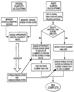
Figure 3 is a chart depicting the logic flow in
carrying out a finite element analysis (FEA) of a forming
model according to the present invention, such that
anisotropic properties of the metal sheet are decoupled
from the analysis;
Figure 4 is a block diagram of a computer system
which may be adapted to carry out the FEA according to the
present invention; and
CA 02349824 2001-05-08
W O 00/29918 PCT/CA99/Ol 087
13
Figure 5 is a chart depicting the logic flow in
designing the tooling and the forming operations required
to produce a part with optimum properties using the
plasticity model according to the present invention.
BEST MODES) FOR CARRYING OUR THE INVENTION
With reference now to the figures, and in particular with
reference to Figure 1, there is depicted the creation of a
metal sheet 10 using a conventional rolling process. As
IO explained further below, various articles may be
fabricated from sheet 10. The forming operations and the
performance of such products may be optimized in
accordance with the present invention. Sheet 10 may be
formed from, e.g., rolled aluminum alloy. The mechanical
(deformation) properties of sheet 10 are anisotropic, as a
result of the orientations of the crystals that make up
the sheet. Thus mechanical properties vary for different
directions in the sheet, as indicated by the three arrows
in Figure 1.
With further reference to Figure 2, a blank 12 cut from
sheet 10 is shaped into an article using tooling 14.
Tooling design and operation and the properties of the
product produced can be optimized by FEA, in accordance
with the present invention. In the depicted embodiment, a
generic representation of the tooling used to produce a
can bottom, the tooling 14 is generally comprised of a
punch 18, a die (or dourer plug) 16 and a retainer ring 20.
Tooling 14 may include other conventional components such
as a ram or piston (not shown) which is attached to punch
18, whereby punch 18 may be forced into die 16 to form
blank 12 into the desired shape.
CA 02349824 2001-05-08
WO OOI29918 PCT/CA99/01087
14
The components of tooling 14 may be constructed using
conventional materials, particularly tool steel or
tungsten carbide. In this particular implementation, the
tooling is designed to form blank 12 into the base of a
beverage can. Those skilled in the art will appreciate,
however, that the present invention is not limited to this
example, as it can be used to design tooling for a wide
assortment of finished products and component parts having
various sizes and shapes.
The present invention provides a novel computational model
for simulating deformation and flow of materials,
particularly metal sheet blanks such as blank 12. This
model can then be used to optimally design tooling and
select material specifications (such as the thickness of
the blank).
As noted above, conventional analysis techniques use
finite element analysis (FEA) to model plasticity and
formability. The present invention improves upon these
techniques by incorporating anisotropic properties of the
blank into a finite element model. The novel
computational model achieves this effect by decoupling the
anisotropic calculations from the FEA, as explained
further below. The result is a model that is not only in
close agreement with experimentally-generated data, but
that also requires much less computational (CPU) time to
run to completion than conventional models that simulate
the forming of anisotropic sheet, and hence is much less
expensive to carry out.
CA 02349824 2001-05-08
WO 00/29918 PCT/CA99/01087
According to an illustrative implementation of the present
invention, a material point simulator (MPS) calculation is
decoupled from the FEA, thereby allowing an isotropic FEA
plasticity model to capture anisotropy. As noted above,
5 the objective of the FEA is to be able to predict the
response of a product to external loading conditions,
which often lead to mechanical instability and snap-
through or buckling. When a validated performance
prediction is required, a forming model must be run prior
10 to the performance model, in order to calculate metal
thinning, levels of workhardening and residual stresses
prior to the imposition of the performance test loading.
For both the forming and performance models, which
15 together constitute the FEA, choice of the appropriate
description of the material behavior is critical to the
predictive capability of the FEA. According to an
illustrative implementation of the present invention, a
material point simulator (MPS) calculation is decoupled
from the FEA, thereby allowing an isotropic (von Mises)
plasticity model to capture material anisotropy.
MPS calculations require experimental measurements of the
crystallographic texture and at least one stress-strain
curve, used to calibrate the hardening law in the MPS.
The so-calibrated MPS calculates a set of stress-strain
curves for various strain paths commonly found in forming
operations. This set of curves will have well-defined
upper and lower bounds.
CA 02349824 2001-05-08
WO 00/29918 PCT/CA99/01087
16
Therefore, the appropriate curve for any specified strain
path lies between two well-defined limits. The FEA
calculations require definition of the geometry and path
of the tooling (generally achieved using an appropriate
CAD package), meshing of the tooling and the blank (e. g.,
the sheet to be formed into a component), definition of
the boundary conditions between the tooling and the blank
and, most importantly, the assigning of a material stress-
strain curve to each element.
The latter step can, according to this invention, be done
in two ways: prior to running the finite element analysis
or during the analysis itself. For the former, the
appropriate stress-strain curve for an element or group of
elements can be assigned by inspection and understanding
of the general nature of the interaction of the tooling
with the blank or by performing an isotropic analysis
(prior to the desired FEA) to determine the strain path
for each element of group of elements and thereby allowing
an appropriate stress-strain path to be assigned to each.
Alternatively, the assignment of the appropriate stress-
strain curve may be updated at each converged step, or at
regular intervals of converged steps, in the analysis by
relating the current plastic strain tensor for each
element to one of the set of stress-strain curves defined
previously. The foregoing method of decoupling material
anisotropy from the FEA is summarized in Figure 3.
The novel computational model of the present invention can
be carried out on the exemplary computer system 30 of
Figure 4. Such a system will contain one or more central
processing units, CPUs, with an appropriate amount of
random access memory, R.AM, and storage capacity, such as
hard disk or tape, IO devices to link to peripheral units,
such as display screens and printers.
CA 02349824 2001-05-08
WO 00/29918 PCT/CA99/01087
17
The system may be stand alone, as for example a single
workstation or personal computer, or may consist of a set
of networked CPUs 32, including a server 34, (generally
with multiple CPUs) and a number of individual
workstations or personal computers, linked together by an
Ethernet or fiber-optic network. The MPS and FEA
calculations may be performed on software, installed on
the CPUs of the network, using either third-party computer
codes (e. g., but not limited to, HKS Inc. Abaqus or LSTC
LS-Dyna) or specialty codes written and developed in-
house.
As noted above, the novel computational model described
herein is used to optimize forming operations, tooling
design and product performance. This process is generally
shown in Figure 5. A specific tooling design for a
particular article is first proposed (50). The procedure
described in Figure 3, performed on the computer system
described in Figure 4, is then applied to the initial
design (52). The "virtual" article whose fabrication is
simulated, is then analyzed for product performance (54).
If the product does not meet specifications (56), the
tooling and its method or operation must be redesigned
(58) .
For example, with reference to tooling 14 of Figure 2, if
the dome reversal pressure of the "virtual" can bottom,
produced by the forming simulation and determined by the
performance analysis, were too low, geometry of the dourer
plug and/or motion of the punch could be altered and the
complete FEA could be repeated. Steps 50 through 58 are
repeated as necessary until a satisfactory design is
found. An essential part of the procedure is validation
of model predictions against one (usually the initial)
design of a prototype component.
CA 02349824 2001-05-08
- WO 00/29918 PCT/CA99/01087
18
This validation exercise provides the confidence that the
model indeed simulates both the forming and performance
operations correctly. Modifications to tooling and
forming operations may then proceed with a reasonable
degree of confidence. Once the optimization procedure
described in Figure 5 is complete, production tooling may
be fabricated (60).
Although the invention has been described with reference
to specific embodiments, this description is not meant to
be construed in a limiting sense. Various modifications
of the disclosed embodiments, as well as alternative
embodiments of the invention, will become apparent to
persons skilled in the art upon reference to the
description of the invention.
For example, while the foregoing description pertains to
metal sheet, the present invention could also be used to
predict deformation and formability of nonmetallic
materials. It is therefore contemplated that such
modifications can be made without departing from the
spirit or scope of the present invention as defined in the
appended claims.
INDUSTRIAL APPLICABILITY
The method embodying the present invention is capable of
being used in the material processing industry.