Note: Descriptions are shown in the official language in which they were submitted.
CA 02349840 2001-05-08
WO 00/31567 PCTNS99/25721 -
-1-
HYDROCARBON EDGE DETECTION USING SEISMIC AMPLITUDE
This invention relates to seismic prospecting for oil and gas reservoirs,
and more specifically it relates to processing seismic data in a high speed
digital
computer using a combination of processing techniques including automated
delta
S amplitude dip (DAD) and amplitude versus offset (AVO) techniques.
BACKGROUND OF THE INVENTION
For many years seismic exploration for oil and gas has involved the
use of a source of seismic energy and its reception by an array of seismic
detectors,
generally referred to as geophones. When used on land, the source of seismic
energy
can be a high explosive charge electrically detonated in a borehole located at
a
selected point on a terrain, or another energy source having capacity for
delivering a
series of impacts or mechanical vibrations to the earths surface. Offshore,
air gun
sources and hydrophone receivers are conunonly used. The acoustic waves
generated
in the earth by these sources are transmitted back from strata boundaries
andlor other
1 S discontinuities and reach the earth's surface at varying intervals of
time, depending
on the distance traversed and the characteristics of the subsurface traversed.
On land
these returning waves are detected by the geophones, which function to
transduce
such acoustic waves into representative electrical analog signals, which are
generally
referred to as traces. In use on land an array of geophones is laid out along
a grid
covering an area of interest to form a group of spaced apart observation
stations
within a desired locality to enable construction of three dimensional (3D)
views of
reflector positions over wide areas. The source, which is offset a desired
distance
from the geophones, injects acoustic signals into the earth, and the detected
signals at
each geophone in the array are recorded for later processing using digital
computers,
where the analog data is generally quantized as digital sample points, e.g.,
one sample
every two milliseconds, such that each sample point may be operated on
individually.
Accordingly, continuously recorded seismic field traces are reduced to
vertical cross
sections and/or horizontal map views which approximate subsurface structure.
The
geophone array is then moved along to a new position and the process is
repeated to
provide a seismic survey.
A seismic data processing technique referred to herein as delta
amplitude dip (DAD) accentuates areas of waveform tuning in hydrocarbon filled
CA 02349840 2001-05-08
WO 00131567 PCT/US99/Z5721 -
-2-
porous formations, and is well suited for directly indicating the presence of
hydrocarbons in those hydrocarbon containing formations. This DAD technique is
disclosed in U.S. Patent Number 5,543,958 issued to Dennis B. Neff, and the
entire
disclosure of this patent is incorporated herein by reference. According to
the DAD
approach, an attribute of a subsurface reflection point is determined from the
delta
amplitude in the direction of maximum dip, normalized by the amount of dip.
This
DAD value of a seismic attribute is derived from traces obtained from
multipoint
coverage of a dipping subsurface interface, and is used to identify the
presence of
hydrocarbons in the subsurface formations. While this DAD technique is
considered
to be a significant exploration and exploitation tool, it requires a
preprocessing step
of manually locating and picking horizons, and accordingly elimination of the
preprocessing step so as to achieve a more fully automated DAD process would
be
highly desirable.
Also, it is well known by persons skilled in the art of seismic
prospecting that the compressional P-wave reflection coefficient at an
interface
separating two media varies with the angle of incidence of seismic energy. A
processing technique referred to as amplitude versus offset (AVO) is well
known by
those skilled in the art for relating the reflected amplitude variation to the
presence of
hydrocarbon accumulations in a subsurface formation. According to the AVO
approach, attributes of a subsurface interface are determined from the
dependence of
the detected amplitude of seismic reflections on the angle of incidence of the
seismic
energy. This AVO approach determines both a normal incidence coefficient of
seismic reflection, and a gradient component of seismic reflection, and the
cross
plotting of normal incidence amplitude and gradient data is often used in the
method
for identifying hydrocarbons. In an AVO processing technique, one derives the
amplitude R of a reflected seismic wave from an interface as a function of the
angle
of incidence 8 from the normal according to the equation:
R~~ = A + Bsin' 8
In this equation, the coefficient A is the normal incidence coefficient,
and the coefficient B is the gradient component, which is representative of
the rate of
change of amplitude with the square of the sine of the angle of incidence.
AVO analysis and processing as an exploration tool for risk analysis
CA 02349840 2001-05-08
WO 00/31567 PCT/US99/257Z1 -
-3-
has been significantly advanced in the last five years through better
processing and
presentation schemes. Accordingly, certain indicators derived from AVO
analysis,
such as using the positive A*B product as a direct indicator of hydrocarbons,
have
been successful in identifying the location of many gas and oil reservoirs.
While
using such indicators, however, many valid hydrocarbon AVO anomalies, which
may
be indicators of hydrocarbon, are overlooked because they are associated with
medium or hard sand layers that do not and should not have a higher amplitude
reflection in the far offsets. Also, false bright spots often remain after AVO
processing. Particularly problematic in AVO processing are the medium
porosity, or
so called Class II sands, which frequently reverse polarity with greater
offset when
gaseous hydrocarbons are present in the formation.
In conventional DAD or AVO processing, multiple seismic traces are
collected from source receiver pairs having different offsets and thus
multiple angles
of incident seismic energy, and where the collected signal traces are each
reflected
from a common subterranean reflection point. Such a group of traces is
referred to
as a common depth point (CDP) gather. Typically, seismic reflection points are
midpoints between the source and receiver pair for various offsets, and as
such this
gather is also often referred to as a common midpoint (CMP) gather.
Accordingly it is desirable to extract more useful subsurface
information from seismic amplitude data without requiring information
regarding
actual properties of the rock.
Again it is desirable to more consistently distinguish sands and porous
carbonates with hydrocarbon from surrounding formations.
Yet again it is desirable to better image the edges of hydrocarbon-
bearing reservoirs.
Then again it is desirable to provide a method and system for
improved processing of seismic data that is compatible with previously
implemented
AVO analysis techniques.
SUMMARY OF THE INVENTION
In accordance with the present invention, I have discovered that the
preprocessing step of locating and picking horizons in DAD processing of
seismic
data can be automated, and further that AVO processing of seismic data can be
CA 02349840 2001-05-08
WO 00/31567 PCT/US99/25721 -
-4-
improved by combining DAD and AVO techniques to generate displays which more
accurately indicate the presence of hydrocarbons in subsurface formations.
Most
significantly, the automated DAD process is able to use AVO data sets such as
(A +
B) or A*B as input to the DAD algorithm. This provides a compounding effect
that
further enhances identification of prospective hydrocarbon reservoirs
regardless of
AVO class, (i.e., bright spot, dim spot, or polarity reversal) by greatly
diminishing
the amplitude of most non-prospective intervals such as shale and silts.
According to a first aspect of this invention, which is more fully
automating the DAD technique, a method involves determining if a dipping
reflection
plane is associated with each depth point in a seismic survey. This method
assumes
that conventional data processing is applied to a 3D data survey up to and
including
migration and generation of CDP or CMP gathers of seismic traces. Then for
each
depth point in the seismic survey a cross correlation involves eight traces
that are
reflected from the perimeter of a three-by-three array of depth points, with
the depth
point under test being positioned in the center of the array. In this cross
correlation
the central trace is individually correlated with its eight adjacent traces
and the
correlation is carried out over a predefined time window, and for a series of
lags.
Next a dipping plane is fitted to the nine traces, including lagged traces,
such that the
cross correlation coherency of traces in the array is optimized for a
particular strike
and dip position of the dipping plane. The strike and dip of this optimal
plane is
recorded for later use in calculating the DAD value.
Next, amplitudes over the plane surface are determined. The
intersected trace amplitudes at the corresponding nine traces of the array are
then
contoured, and an amplitude vector is determined in the direction of dip. The
amplitude of the vector is then normalized by the amount of dip, as per the
disclosure
in the previously incorporated '958 patent, to calculate the DAD value. The
thus
calculated DAD value is then written to a DAD 3D data volume corresponding to
the
time position of the center depth point in the array. This process is then
repeated for
every trace and time/depth sample of the 3D volume.
According to a second aspect of this invention, conventional AVO data
sets such as an (A + B) or A*B section are integrated with DAD processing so
as to
suppress false A*B anomalies which are often present in conventional A*B
sections,
CA 02349840 2001-05-08
WO 00/31567 PCTNS99/25721 -
-5-
but are not indicators of hydrocarbon. This combined DAD AVO method therefore
provides interpretation enhancements which further reduce exploration risk
compared
to either DAD or AVO techniques used alone.
In yet another aspect of the invention apparatus comprises a computer
programmed to implement the DAD algorithm using either field data or AVO data
sets as inputs to the DAD algorithm. For large scale 3D exploration data, the
computer is preferably a massively parallel machine.
Accordingly, the DAD algorithm is an expedient and effective method
to enhance whatever hydrocarbon effect is present in 3D seismic data.
Still other objects and advantages of the present invention will become
readily apparent to those skilled in the art from the following detailed
description and
the drawings, wherein there is shown and described only the preferred
embodiments
of this invention.
BRIEF DESCRIPTION OF THE DRAWINGS
FIG. 1 is a perspective view of an arrangement of geophones for
obtaining a seismic data volume, and further illustrates a three-by-three
trace array for
locating a dipping subsurface plane according to this invention.
FIG. 2 is a graph illustrating seismic amplitude vs. pay thickness for
three types of porous reservoirs.
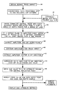
FIG. 3 is a simplified flow diagram illustrating programmed steps for a
DAD algorithm used to create a DAD or an AVODAD display.
FIG. 4 is a structure contour map indicating the direction of strike and
dip.
FIG. 5 is an amplitude contour map indicating that hydrocarbon effects
are most indicative in the direction of dip.
FIG. 6 is a display of a conventional amplitude timeslice.
FIG. 7 is a display of the data in Fig. 6 with DAD processing.
FIG. 8 is a display with A + B DAD processing.
DETAILED DESCRIPTION OF THE INVENTION
Amplitude and structure maps have long been used to define the limits
of hydrocarbon reservoirs, particularly when the reservoirs are associated
with seismic
"bright spots." Amplitude can, however, be ambiguous in reservoirs where the
CA 02349840 2001-05-08
WO 00/31567 PCT/US99/25721-
-6-
seismic response is a "dim spot" or a polarity reversal. The basic premise of
the
DAD algorithm is that hydrocarbons will most dramatically affect the seismic
amplitudes when the data pass through a pay thickness that causes waveform
tuning,
and the maximum delta amplitude change will be seen on profiles that are dip
oriented. FIG. 2 shows three possible amplitude tuning curves, i.e., for
reservoirs
with low, medium and high porosity. In each case, near the zero limit of pay
thickness, the slope of the amplitude curve shown at letters A, B and C, is
relatively
high regardless of the initial amplitude value at zero pay thickness.
Accordingly, by
testing for the amplitude change at the edge of a reservoir, the ambiguity of
a "bright
spot" versus a "dim spot" play can be eliminated.
As previously mentioned, a seismic data processing technique which
discloses the DAD algorithm to enhance detection of hydrocarbons is disclosed
in the
incorporated patent U.S. 5,542,958. According to the present invention,
however, the
method for locating hydrocarbon reservoirs disclosed in that patent is
enhanced by
1 S automatically locating a dipping subterranean surface associated with each
depth
point in a seismic survey, which is necessary for DAD processing.
Referring now to FIG. 3, a first a step as shown in block 30 is to
obtain a set of seismic data in the form of signal traces distributed over a
volume of
the earth, and then processing the data as shown in block 32. Methods by which
such data is obtained, reduced to digital format, and processed up to and
including
migration and generation of CDP gathers of the seismic traces is well known to
those
skilled in the art.
The next step shown in block 34, is to cross correlate traces reflected
from a three-by-three array of depth points in a seismic survey, and is
applied to each
time sample of each depth point in the survey. This correlation is carried out
over a
predetermined time window such as about 28 milliseconds, and compares the
trace
associated with the central depth point with each of eight perimeter traces,
and for a
series of lags of the 8 neighbor traces.
This step is better illustrated in FIG. 1, which is a perspective view of
a 3D seismic trace volume of the eaxth, and which shows an example of a nine-
spot
array of depth points illustrated at 20. Referring still to FIG. 1, a volume
of the earth
is generally illustrated at 21. On the surface of the earth 22 a large array
of
CA 02349840 2001-05-08
WO 00/31567 PCT/US99/Z5721 -
_'7_
geophones is shown by the numerous circles 24. Also illustrated in more detail
is the
exemplary 3 x 3 array of geophones, which are shown with associated zero
offset
seismic traces generally illustrated at 26. While zero offset traces are
illustrated at
26, in practice these traces can be stacked, migrated or AVO derived traces
such as
A+B or A*B. Further illustrated is the central trace 2S. Although not
illustrated,
each geophone 24 has an associated trace, but for simplicity only the zero-
offset
traces 26 associated with the array are illustrated in Fig. 1. An example of a
dipping
plane, which is mathematically inserted in the array to linearly connect trial
amplitude
events in the array of traces 26 in FIG. 1, is illustrated at 28 in that
figure.
Referring again to FIG. 3, and in particular to block 36, various
locations of the dipping plane are tested using trace lagging techniques to
adjust the
strike and dip of the plane. The lagging technique generally limits the dip of
the
plane to not more than plus or minus forty-five degrees. The final position of
the
dipping plane is determined by selecting the location (strike and dip) of the
plane that
optimizes coherency of all eight traces that are cross correlated with the
central trace.
Cross correlation of seismic data for comparing similarity of
neighboring traces, as used in this invention, is well known to those skilled
in the art.
For further details regarding correlation see, for example, Anstey, N. A.,
"Correlation
Techniques," Journal of the Canadian Society of Exploration Geophysists, 2, 55-
82.
Next as illustrated at 38 in FIG. 3, amplitudes are extracted along the
DAD plane for the nine traces including, if necessary, interpolation along the
traces
between sample points, and then the extracted amplitudes are contoured as
stated in
block 40. A structure contour map showing an example of strike and dip of a
surface
is illustrated in FIG. 4. Advancing to block 42, an amplitude vector is
determined in
the direction of dip, and in block 44 the normalized delta amplitude over dip
(i.e., the
DAD value) is determined. In the normalization algorithm of block 44, a lower
and
an upper limit are applied to dip to avoid division by zero or other
unrealistic results.
This amplitude normalization is more fully described in the previously
incorporated
patent.
According to the second aspect of this invention a DAD algorithm is
applied to AVO data sets as shown in the optional input block 31 to the DAD
algorithm in FIG. 3. Conventional AVO analysis is well known in the art, and
more
CA 02349840 2001-05-08
WO 00/31567 PCTNS99/25721 -
_g_
recently developed AVO data sets such as (A+B) and .A*B can provide input data
sets for DAD analysis. A method for hydrocarbon detection using AVO analysis
is
disclosed in U.S. Patent No. 5,784,334 issued to A.G. Sena et al., the
disclosure of
which relating to conventional AVO analysis resulting in creation of direct
hydrocarbon indicators such as A*B data sets, is incorporated herein by
reference.
EXAMPLE MAPS
Any surface for which time or depth structure and an amplitude
horizon exist can be converted to a DAD map, wherein high DAD values that
parallel
structural contours represent prospective hydrocarbon edges. The following
examples
were performed in conjunction with seismic workstation displays such as
SeisWorks,
available from Landmark Graphics Corporation of Houston, Texas.
This example compares conventional amplitude, DAD and A + g DAD timeslices.
Fig. 6 is an example of a conventional seismic amplitude timeslice
representing positive and negative polarity. This map is coincident with a
gas/water
contact in a high porosity sandstone reservoir and shows high amplitude, which
includes the area at the letter "a". Fig. 7 which is the equivalent DAD
timeslice of
FIG. 6, has an event coincident with the structural limit of the reservoir and
a
lineation coincident with the updip fault bounded edge. Elevated DAD values
are not
present at the letter "a", which area is beyond the limits of this productive
reservoir.
FIG. 8 shows the further improvement of A + B DAD timeslices at this gas/water
contact. This figure has amplitude contrasts for hydrocarbon indicators which
are
five to ten times brighter as compared to the background levels.
The invention as described and illustrated herein is an effective method
and apparatus to enhance whatever hydrocarbon edge effect may be present in 3D
seismic data and accordingly provides interpretation enhancements which reduce
exploration risks. However, those skilled in the art will recognize that many
modifications and variations of this invention are possible in light of the
above
teachings without departing from the spirit of the invention. It is understood
that the
present invention is not intended to be limited by the particular features
described and
illustrated in the specification and drawings but the concept of this
invention is to be
measured by the scope of the appended claims.