Language selection

Search

Patent 2350063 Summary

Third-party information liability

Some of the information on this Web page has been provided by external sources. The Government of Canada is not responsible for the accuracy, reliability or currency of the information supplied by external sources. Users wishing to rely upon this information should consult directly with the source of the information. Content provided by external sources is not subject to official languages, privacy and accessibility requirements.

Claims and Abstract availability

Any discrepancies in the text and image of the Claims and Abstract are due to differing posting times. Text of the Claims and Abstract are posted:

  • At the time the application is open to public inspection;
  • At the time of issue of the patent (grant).
(12) Patent: (11) CA 2350063
(54) English Title: QUICK-STRIP STRETCHER FOR TUBULAR FABRIC
(54) French Title: DISPOSITIF D'ETIRAGE RAPIDEMENT DEMONTABLE POUR TISSU TUBULAIRE
Status: Deemed expired
Bibliographic Data
(51) International Patent Classification (IPC):
  • D06C 5/00 (2006.01)
(72) Inventors :
  • MILANESE, RENZO (Italy)
  • FERRARO, GIANCARLO (Italy)
(73) Owners :
  • FERRARO S.P.A. (Italy)
(71) Applicants :
  • FERRARO S.P.A. (Italy)
(74) Agent: LONG AND CAMERON
(74) Associate agent:
(45) Issued: 2004-09-21
(86) PCT Filing Date: 1999-10-28
(87) Open to Public Inspection: 2000-05-11
Examination requested: 2001-08-03
Availability of licence: N/A
(25) Language of filing: English

Patent Cooperation Treaty (PCT): Yes
(86) PCT Filing Number: PCT/IT1999/000345
(87) International Publication Number: WO2000/026460
(85) National Entry: 2001-04-26

(30) Application Priority Data:
Application No. Country/Territory Date
MI98A002372 Italy 1998-11-04

Abstracts

English Abstract


A stretcher for tubular knitwear fabric has two stretcher arms provided with
shaped rings, driving
wheels and two pairs of inclined wheels in correspondence with the shaped
rings. The inclined
wheels are respectively mounted on two plates which are adjacent arms and
detachably
interconnected to each other, arms being disengageable from the plates to
facilitate maintenance and
cleaning.


French Abstract

L'invention concerne un dispositif d'étirage comprenant deux bras d'étirage (1), des anneaux profilés fixes (5), des roues meneuses (2a, 2b), et deux paires de roues inclinées (4, 4') correspondant audits anneaux profilés (5). Ces roues inclinées (4, 4') sont montées respectivement sur deux plaques (12, 13) adjacentes aux bras susmentionnés (1) et interconnectées de manière amovible les unes aux autres, lesdits bras (1) pouvant ainsi être détachés des plaques (12, 13).

Claims

Note: Claims are shown in the official language in which they were submitted.


-4-

Claims

1. A stretcher comprising: two stretcher arms, said stretcher arms being
provided with shaped
rings, driving wheels and two pairs of inclined wheels in correspondence with
said shaped
rings, wherein said inclined wheels are respectively mounted on two plates
which are
adjacent said arms and detachably interconnected to each other, said arms
being
disengageable from the plates.

2. A stretcher as claimed in claim 1, comprising at least two studs detachably
connecting the
plates.

3. A stretcher as claimed in claim 2, wherein said studs (14) are each mounted
in respective
pairs of supports which are respectively parts of the plates, said supports
supporting
respective ones of the inclined wheels.

4. A stretcher as claimed in claim 1, 2 or 3, wherein magnets are adapted,
depending on their
positions, to attract said arms outwardly with the rings removed from the
inclined wheels or
not to attract said arms, thereby allowing said arms to be freely disengaged
from said plates.

Description

Note: Descriptions are shown in the official language in which they were submitted.


CA 02350063 2003-12-02
1011 P4CA
The present invention relates a stretcher for tubular knitwear fabric,
especially for application to
calenders or other machines for the treatment of tubular fabric.
It is known that stretchers are used during the finishing step of tubular
knitwear articles for stretching
and spreading the tubular article in order to ease the finishing operations.
This operation causes
impurities to be deposited onto plates and onto members forming parts of the
stretcher.
It is an object of the present invention to mitigate this draw-back by
adapting the stretcher such that
it can be dismounted, thereby providing the benefit of possibly providing in a
simple fast way for
the maintenance and clean-up of the whole stretcher.
According to the present invention, a stretcher comprising: two stretcher
arms, said stretcher arms
being provided with shaped rings, driving wheels and two pairs of inclined
wheels in correspondence
with said shaped rings, wherein said inclined wheels are respectively mounted
on two plates which
are adjacent said arms and detachably interconnected to each other, said arms
being disengageable
from the plates.
Preferably, the stretcher comprises at least two studs detachably connecting
the plates, the studs
being each mounted in a respective pair of supports which are respectively
parts of the plates, the
supports supporting respective ones of the inclined wheels.
Magnets may be adapted, depending on their positions, to attract the arms
outwardly with the rings
removed from the inclined wheels or not to attract the arms, thereby allowing
the arms to be freely
disengaged from the plates.
The features, advantages and the solution of the technical problem at the
basis of the invention will
be evident from the following detailed description of a preferred, non-
exclusive embodiment of the
subject stretcher which is illustrated in a merely illustrative, non-limiting
way in the accompanying
figures, in which:


CA 02350063 2003-12-02
-2-
FIG. 1 shows a partial perspective view of the stretcher, and
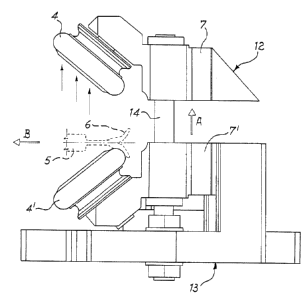
FIG. 2 shows a partial view of the stretcher in the dismounting step.
In the drawings, there is shown a stretcher which comprises: two stretcher
arms 1, only the right-side
stretcher being represented in FIG. 1; upper driving wheels 2a and lower
driving wheels 2b that are
interconnected by means of an elastic belt that is not shown on the figure;
idler pulleys 3; and
inclined wheels 4 4'.
As can be seen from FIG. 1, the stretcher arm 1 carries rings 5 which have
peripheries 6 shaped as
shown in FIG. 2. These rings are arranged in front of bulging portions of the
driving wheels 2a and
2b. These have in turn supports 7, T which support the wheels 4, 4' with the
axes of the latter
inclined. The wheels 4 have peripheries which are spaced from the peripheries
6 of the rings 5
magnetic attraction forces acting on the arms, as will be explained
hereinafter.
The transportation of the tubular fabric is carried out by means of belts (not
shown) which are wound
around a set of pulleys 8 idly supported on the arms 1, and along the contour
of the driving wheels
2a and 2b and of the rings 5.
Both of the inclined wheels 4 are driven as they are connected to each other
by means of an elastic
belt (not shown) which are wound around the driving wheels 2a and 2b and the
idler pulleys 3.
Similarly, the inclined wheels 4', shown in FIG. 2 as coupled to wheels 4, are
driven because they
are connected by means of belts to the same driving wheels 2a and 2b.
Wheels 4 and 4' are kept spaced apart from the rings 5 by means of magnets 9
that attract the arms
outwardly, together with the rings 5, which in turn are attracted against the
driving wheels 2a and
2b.


CA 02350063 2003-12-02
-3-
Moreover it is to be noted that the attraction force of magnets 9 is
adjustable, so that the gap between
the rings 5 and the inclined wheels 4 and 4' is assured. The adjustment is
obtained by means of a
mechanism that causes the magnets 9 to move towards or away from the arms 1,
respectively. In fact,
the magnets 9 are connected to the mechanism, which is provided with an
adjustment handgrip 10
adapted to cause the magnets 9 to move towards to or away from the supports
11, which are fixedly
connected to the bars 1.
The two pairs of inclined wheels 4, 4' are respectively mounted on the
supports 7, 7' that are integral
with the plates 12 and 13, which are detachably connected to each other, and
the arms 1 are
disengageable from the plates 12 and 13. In particular, two studs 14
detachably connect the plates
12, 13 and are respectively mounted on the supports 7, 7'.
The inclined wheels 4 are supported by the upper support 7, whilst the
inclined wheels 4' are
supported by the lower support T.
The operation of the above-described device is as follows:
the magnets 9 arc moved away from the arms 1, so that the latter together with
the rings 5 are kept
in the right position because the inclined wheels 4, 4' press against the
bulging portions of the rings
5. Thereafter the supports 7 are slipped offthe studs 14 according to arrow A
and the arms together
with the rings are removed according to arrow B, as shown in FIG. 2. Thus
maintenance and clean-
up from the impurities that deposit during operation onto all the parts of the
group, that is onto the
plates 12 and 13 and onto the arms 1, will be convenient and fast.
Modifications of a practical applicative nature may possibly be made in the
construction details of
the embodiment within the range of the invention as claimed hereinbelow.

Representative Drawing
A single figure which represents the drawing illustrating the invention.
Administrative Status

For a clearer understanding of the status of the application/patent presented on this page, the site Disclaimer , as well as the definitions for Patent , Administrative Status , Maintenance Fee  and Payment History  should be consulted.

Administrative Status

Title Date
Forecasted Issue Date 2004-09-21
(86) PCT Filing Date 1999-10-28
(87) PCT Publication Date 2000-05-11
(85) National Entry 2001-04-26
Examination Requested 2001-08-03
(45) Issued 2004-09-21
Deemed Expired 2005-10-28

Abandonment History

There is no abandonment history.

Payment History

Fee Type Anniversary Year Due Date Amount Paid Paid Date
Registration of a document - section 124 $100.00 2001-04-26
Application Fee $300.00 2001-04-26
Request for Examination $200.00 2001-08-03
Maintenance Fee - Application - New Act 2 2001-10-29 $50.00 2001-09-28
Maintenance Fee - Application - New Act 3 2002-10-28 $50.00 2002-10-03
Maintenance Fee - Application - New Act 4 2003-10-28 $50.00 2003-10-02
Final Fee $150.00 2004-07-07
Owners on Record

Note: Records showing the ownership history in alphabetical order.

Current Owners on Record
FERRARO S.P.A.
Past Owners on Record
FERRARO, GIANCARLO
MILANESE, RENZO
Past Owners that do not appear in the "Owners on Record" listing will appear in other documentation within the application.
Documents

To view selected files, please enter reCAPTCHA code :


To view images, click a link in the Document Description column. To download the documents, select one or more checkboxes in the first column and then click the "Download Selected in PDF format (Zip Archive)" or the "Download Selected as Single PDF" button.

List of published and non-published patent-specific documents on the CPD .

If you have any difficulty accessing content, you can call the Client Service Centre at 1-866-997-1936 or send them an e-mail at CIPO Client Service Centre.


Document
Description 
Date
(yyyy-mm-dd) 
Number of pages   Size of Image (KB) 
Cover Page 2004-08-19 1 38
Abstract 2001-04-26 1 15
Representative Drawing 2001-07-31 1 10
Description 2001-04-26 3 120
Claims 2001-04-26 1 30
Drawings 2001-04-26 2 47
Cover Page 2001-07-31 1 39
Description 2003-12-02 3 127
Claims 2003-12-02 1 25
Abstract 2003-12-02 1 12
Fees 2002-10-03 1 32
Assignment 2001-04-26 4 188
PCT 2001-04-26 12 482
Correspondence 2001-07-09 3 108
Assignment 2001-04-26 6 280
Prosecution-Amendment 2001-08-03 1 29
Prosecution-Amendment 2001-10-25 1 27
Prosecution-Amendment 2003-10-22 1 33
Fees 2003-10-02 1 27
Prosecution-Amendment 2003-12-02 7 207
Fees 2001-09-28 1 30
Correspondence 2004-07-07 1 25