Language selection

Search

Patent 2350166 Summary

Third-party information liability

Some of the information on this Web page has been provided by external sources. The Government of Canada is not responsible for the accuracy, reliability or currency of the information supplied by external sources. Users wishing to rely upon this information should consult directly with the source of the information. Content provided by external sources is not subject to official languages, privacy and accessibility requirements.

Claims and Abstract availability

Any discrepancies in the text and image of the Claims and Abstract are due to differing posting times. Text of the Claims and Abstract are posted:

  • At the time the application is open to public inspection;
  • At the time of issue of the patent (grant).
(12) Patent: (11) CA 2350166
(54) English Title: A METHOD AND MACHINE FOR TAMPING A TRACK
(54) French Title: TECHNIQUE ET MACHINE POUR LE BOURRAGE D'UN RAIL
Status: Expired and beyond the Period of Reversal
Bibliographic Data
(51) International Patent Classification (IPC):
  • E01B 27/17 (2006.01)
(72) Inventors :
  • THEURER, JOSEF (Austria)
  • WORGOTTER, HERBERT (Austria)
(73) Owners :
  • FRANZ PLASSER BAHNBAUMASCHINEN-INDUSTRIEGESELLSCHAFT M.B.H.
(71) Applicants :
  • FRANZ PLASSER BAHNBAUMASCHINEN-INDUSTRIEGESELLSCHAFT M.B.H. (Austria)
(74) Agent: RICHES, MCKENZIE & HERBERT LLP
(74) Associate agent:
(45) Issued: 2005-08-09
(22) Filed Date: 2001-06-08
(41) Open to Public Inspection: 2001-12-09
Examination requested: 2002-04-10
Availability of licence: N/A
Dedicated to the Public: N/A
(25) Language of filing: English

Patent Cooperation Treaty (PCT): No

(30) Application Priority Data:
Application No. Country/Territory Date
GM 431/2000 (Austria) 2000-06-09

Abstracts

English Abstract

A track lifting section (19), delimited by two rail undercarriages (4), of a machine (1) for tamping a track is extended in the longitudinal direction of the track in a first working pass for lifting the track and introducing ballast underneath the track 2. In a further working pass for producing the final desired position and for tamping the track (2), the track lifting section (19) is shortened.


French Abstract

Une section de soulèvement de rail (19), délimitée par deux boggies (4), d'une machine (1) de bourrage d'un rail est allongée dans la direction longitudinale du rail dans une première passe pour soulever le rail et placer un ballast sous le rail 2. Au cours d'une passe ultérieure visant à obtenir la position désirée finale et à bourrer le rail (2), la section de soulèvement de rail (19) est raccourcie.

Claims

Note: Claims are shown in the official language in which they were submitted.

6
Claims
1. A method of tamping a track, wherein the track (2) to be lifted and
tamped is delimited by two rail undercarriages (4), thus forming a track
lifting
section (19), wherein, in a first working pass, the track lifting section (19)
is
extended in the longitudinal direction of the track for a track lifting
operation
and for introducing ballast underneath the track (2), and that, in a further
working pass for producing a final desired position and tamping the track (2),
the track lifting section (19) is shortened.
2. A method according to claim 1, wherein the alteration of the length of
the track lifting section (19) is accomplished by lifting or lowering a
satellite
frame (5) relative to a machine frame (3) of the machine (1), the satellite
frame (5) being connected to a tamping unit (8), a track lifting-lining unit
(9)
and a rail undercarriage (4).
3. A machine for tamping a track (2), including a machine frame (3)
supported at the ends by rail undercarriages (4) and travelling on the track
(2), and a satellite frame (5) arranged between the undercarriages (4), the
satellite frame including a track lifting-lining unit (9) and a tamping unit
(8) and
being connected at one end by means of a joint (7) to the machine frame (3)
for displacement in the longitudinal direction of the machine and having an
undercarriage (4) at the other end for support on the track (2), wherein, in a
region of the undercarriage (4) connected to the satellite frame (5), the
satellite frame (5) is connected to the frame (3) by a drive (20) , for
lifting the
satellite frame (5) from a position supported on the track (2) to a position
lifted from the track (2), the drive (20) being connected to guide rollers
(21)
which are mounted on the machine frame (3) for displacement in the
longitudinal direction of the machine.

Description

Note: Descriptions are shown in the official language in which they were submitted.


CA 02350166 2001-06-08
1
0007
ORIGINAL TEXT
Ma/sp
A method and machine for tamping a track
The invention relates to a method of tamping a track, wherein the track to be
lifted and tamped is delimited by two rail undercarriages, thus forming a
track
lifting section, and to a machine for tamping a track.
From GB 2 151 675, a tamping machine is known which is supported at each
end on a respective rail undercarriage and by means of these defines a track
lifting section. Provided in the space between the two rail undercarriages is
a
satellite frame, mounted for displacement in the longitudinal direction of the
machine, which is equipped with a tamping unit for tamping the track as well
as
a track lifting and lining unit. During working operations, the machine
travels
continuously while the satellite frame is advanced in steps for tamping the
individual sleepers of the track.
A tamping machine which likewise travels continuously during working
operations is known according to US 4 644 868, with a satellite frame being
displaceable relative to the machine frame. A track lifting and lining unit is
longitudinally displaceably mounted on the machine frame and thus is also
displaceable relative to the machine frame during working operations. The
track
lifting section is delimited, on the one hand, by the front rail undercarriage
of the
machine, with regard to the working direction, and, on the other hand, by a
rail
undercarriage connected to the satellite frame. Within the track lifting
section,
the lifting of the track into the desired position as well as the tamping
thereof
takes place.
Finally, a further tamping machine still is known according to US 4 794 862,
on
which machine a chute for ejecting ballast is provided within the tamping
section.

CA 02350166 2001-06-08
2
With that, the track is ballasted in an optimal way in connection with the
track
position correction to achieve a durable track position.
The object of the invention lies in providing a track tamping method of the
specified kind with which even a freshly ballasted track can be tamped
quickly.
Additionally, it is the object of the invention to create a machine for
tamping a
track which may be used in an optimal way both for tamping a freshly ballasted
track as well as for normal tamping.
The earlier-mentioned object of the invention is achieved in that in a method
of
tamping a track, in a first working pass, the track lifting section is
extended in the
longitudinal direction of the track for a track lifting operation and for
introducing
ballast underneath the track, and that, in a further working pass for
producing
the final desired position and tamping the track, the track lifting section is
shortened.
By virtue of extending the track lifting section delimited by the rail
undercarriages, it is possible to lift the track to a greater height without
thereby
overstressing the rails with regard to the bending line. This particularly
high
lifting of the track has the advantage that, within the scope of a single
working
pass, a voluminous ballast delivery is possible particularly in connection
with
newly ballasting the track. As soon as all of the new ballast is located
underneath the track, it is possible by simply shortening the track lifting
section
to carry out right away the concluding, permanent position correction and
tamping of the track.
The object of creating a machine is achieved in that, in the region of the
undercarriage connected to the satellite frame, the satellite frame is
connected
by means of a drive to guide rollers which are mounted on the machine frame
for
displacement in the longitudinal direction of the machine.

CA 02350166 2004-11-24
3
By means of this structurally very simple solution it is possible to realize
the
particular advantage that the track lifting section can be changed by merely
actuating drives, without further retooling operations being necessary for
carrying out the tamping of the track. Above all, the particular efficiency of
the
tamping machine, travelling continuously during working operations, is
preserved fully without restriction, both in the extended and in the normal
mode of operation.
Additional advantageous embodiments of the invention become apparent
from the disclosure and the drawings.
The invention will be described in more detail below with reference to
embodiments represented in the drawings in which:
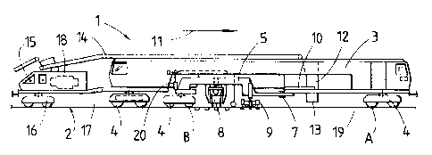
Fig. 1 shows a simplified side view of a tamping machine having a
satellite frame displaceable relative to a machine frame,
Fig. 2 shows an enlarged side view of a portion of the tamping
machine,
Figs. 3 and 4 each show a schematic representation of the tamping
machine with different tamping sections, and
Fig. 5 shows a greatly simplified side view of a further embodiment of a
tamping machine designed in accordance with the invention.
A machine 1, visible in Figs. 1 and 2, for tamping a track 2 has an elongated
machine frame 3 which is supported at its ends on the track 2 by means of
rail undercarriages 4. Provided between these two rail undercarriages 4
located at the ends is a satellite frame 5 which is supported, on the one
hand,
on the track 2 by means of a rail undercarriage 4 and, on the other hand, on
the machine

CA 02350166 2001-06-08
4
frame 3 with the aid of a joint 7. The satellite frame 5, equipped with a
tamping
unit 8 as well as a track lifting-lining unit 9, is displaceable relative to
the
machine frame 3 by means of a displacement drive 10.
Provided in front of the satellite frame 5 and behind the forwardly located
rail
undercarriage 4, with regard to the working direction of the machine 1
represented by an arrow 11, is a ballast chute 12 with outlet openings 13
positioned above the track 2. Furthermore, the machine 1 has a ballast
conveyor
14, extending in the longitudinal direction of the machine, by means of which
ballast may be transported from a rear machine end 15 to the ballast chute 12.
The rear machine end 15 is formed by a frame extension 17, supportable on a
rail undercarriage 16, which is equipped with a motor unit 18 and
articulatedly
connected to the machine frame 3.
A track lifting section 19, intended for lifting the track 2 for the track
position
correction and for tamping, is delimited, on the one hand, by the front rail
undercarriage 4 of the machine 1 and, on the other hand, by the rail
undercarriage 4 of the satellite frame 5. This track lifting section 19,
suited for
normal tamping, is denoted by points A and B in Figs. 1 and 3. As can be seen
in
particular in Fig. 2, the satellite frame 5 is connected in the region of its
rail
undercarriage 4 by means of a hydraulic drive 20 to guide rollers 21 which are
displaceably mounted on a guide 22, extending in the longitudinal direction of
the machine and connected to the machine frame 3. By means of the hydraulic
drive 20, the satellite frame 5 may optionally be lifted from a position of
being
supported on the track 2 into a position raised from the track 2 (see
Fig. 4).
The mode of operation of the machine 1 will be described in more detail below.
For the purpose of freshly ballasting the track 2, correspondingly large
amounts
of ballast are discharged via the ballast chute 12 onto the track 2. The
satellite

CA 02350166 2001-06-08
frame 5 is raised off the track 2 by actuation of the hydraulic drives 20 (see
Fig.
4). Thus, an extended track lifting section 19 is created, delimited by the
front
and the rear rail undercarriage 4 of the machine 1 and marked by A and C. In
this extended track lifting section it is now possible to lift the track to a
greater
height by means of the track lifting-lining unit 9, so that, along with the
increased
track lift, also larger amounts of ballast fall through the track onto the
ballast
bed. As soon as the desired amount of ballast is present underneath the track
2,
normal tamping can be carried out by supporting the satellite frame 5 on the
track 2 while releasing the hydraulic drives 20 (see Fig. 3). This causes an
automatic shortening of the track lifting section 19 to a length denoted by
points
A and B.
In Fig. 5, a machine 1 is shown in which the tamping unit 8 as well as the
track
lifting-lining unit 9 are fastened directly to the machine frame 3. The rear
rail
undercarriage 4 is displaceable by means of a drive 23 from a forward position
for normal tamping operation, represented in solid lines, into a rear end
position
(dash-dotted representation). With this, it is also possible to extend the
track
lifting section 19, if needed.

Representative Drawing
A single figure which represents the drawing illustrating the invention.
Administrative Status

2024-08-01:As part of the Next Generation Patents (NGP) transition, the Canadian Patents Database (CPD) now contains a more detailed Event History, which replicates the Event Log of our new back-office solution.

Please note that "Inactive:" events refers to events no longer in use in our new back-office solution.

For a clearer understanding of the status of the application/patent presented on this page, the site Disclaimer , as well as the definitions for Patent , Event History , Maintenance Fee  and Payment History  should be consulted.

Event History

Description Date
Time Limit for Reversal Expired 2018-06-08
Letter Sent 2017-06-08
Grant by Issuance 2005-08-09
Inactive: Cover page published 2005-08-08
Inactive: Final fee received 2005-05-25
Pre-grant 2005-05-25
Notice of Allowance is Issued 2005-05-05
Letter Sent 2005-05-05
Notice of Allowance is Issued 2005-05-05
Inactive: Approved for allowance (AFA) 2005-04-05
Amendment Received - Voluntary Amendment 2004-11-24
Inactive: S.30(2) Rules - Examiner requisition 2004-08-04
Letter Sent 2002-05-13
Request for Examination Requirements Determined Compliant 2002-04-10
All Requirements for Examination Determined Compliant 2002-04-10
Request for Examination Received 2002-04-10
Application Published (Open to Public Inspection) 2001-12-09
Inactive: Cover page published 2001-12-09
Inactive: First IPC assigned 2001-08-09
Inactive: Filing certificate - No RFE (English) 2001-07-11
Filing Requirements Determined Compliant 2001-07-11
Letter Sent 2001-07-11
Application Received - Regular National 2001-07-11

Abandonment History

There is no abandonment history.

Maintenance Fee

The last payment was received on 2005-04-15

Note : If the full payment has not been received on or before the date indicated, a further fee may be required which may be one of the following

  • the reinstatement fee;
  • the late payment fee; or
  • additional fee to reverse deemed expiry.

Please refer to the CIPO Patent Fees web page to see all current fee amounts.

Owners on Record

Note: Records showing the ownership history in alphabetical order.

Current Owners on Record
FRANZ PLASSER BAHNBAUMASCHINEN-INDUSTRIEGESELLSCHAFT M.B.H.
Past Owners on Record
HERBERT WORGOTTER
JOSEF THEURER
Past Owners that do not appear in the "Owners on Record" listing will appear in other documentation within the application.
Documents

To view selected files, please enter reCAPTCHA code :


To view images, click a link in the Document Description column. To download the documents, select one or more checkboxes in the first column and then click the "Download Selected in PDF format (Zip Archive)" or the "Download Selected as Single PDF" button.

List of published and non-published patent-specific documents on the CPD .

If you have any difficulty accessing content, you can call the Client Service Centre at 1-866-997-1936 or send them an e-mail at CIPO Client Service Centre.


Document
Description 
Date
(yyyy-mm-dd) 
Number of pages   Size of Image (KB) 
Representative drawing 2001-11-13 1 10
Abstract 2001-06-08 1 14
Description 2001-06-08 5 213
Claims 2001-06-08 1 51
Drawings 2001-06-08 2 39
Cover Page 2001-12-07 1 35
Description 2004-11-24 5 210
Abstract 2004-11-24 1 10
Claims 2004-11-24 1 40
Representative drawing 2005-07-29 1 10
Cover Page 2005-07-29 1 35
Courtesy - Certificate of registration (related document(s)) 2001-07-11 1 112
Filing Certificate (English) 2001-07-11 1 163
Acknowledgement of Request for Examination 2002-05-13 1 179
Reminder of maintenance fee due 2003-02-11 1 106
Commissioner's Notice - Application Found Allowable 2005-05-05 1 162
Maintenance Fee Notice 2017-07-20 1 178
Fees 2003-04-07 1 35
Fees 2004-04-15 1 35
Fees 2005-04-15 1 37
Correspondence 2005-05-25 1 35