Sélection de la langue

Search

Sommaire du brevet 2350166 

Énoncé de désistement de responsabilité concernant l'information provenant de tiers

Une partie des informations de ce site Web a été fournie par des sources externes. Le gouvernement du Canada n'assume aucune responsabilité concernant la précision, l'actualité ou la fiabilité des informations fournies par les sources externes. Les utilisateurs qui désirent employer cette information devraient consulter directement la source des informations. Le contenu fourni par les sources externes n'est pas assujetti aux exigences sur les langues officielles, la protection des renseignements personnels et l'accessibilité.

Disponibilité de l'Abrégé et des Revendications

L'apparition de différences dans le texte et l'image des Revendications et de l'Abrégé dépend du moment auquel le document est publié. Les textes des Revendications et de l'Abrégé sont affichés :

  • lorsque la demande peut être examinée par le public;
  • lorsque le brevet est émis (délivrance).
(12) Brevet: (11) CA 2350166
(54) Titre français: TECHNIQUE ET MACHINE POUR LE BOURRAGE D'UN RAIL
(54) Titre anglais: A METHOD AND MACHINE FOR TAMPING A TRACK
Statut: Périmé et au-delà du délai pour l’annulation
Données bibliographiques
(51) Classification internationale des brevets (CIB):
  • E01B 27/17 (2006.01)
(72) Inventeurs :
  • THEURER, JOSEF (Autriche)
  • WORGOTTER, HERBERT (Autriche)
(73) Titulaires :
  • FRANZ PLASSER BAHNBAUMASCHINEN-INDUSTRIEGESELLSCHAFT M.B.H.
(71) Demandeurs :
  • FRANZ PLASSER BAHNBAUMASCHINEN-INDUSTRIEGESELLSCHAFT M.B.H. (Autriche)
(74) Agent: RICHES, MCKENZIE & HERBERT LLP
(74) Co-agent:
(45) Délivré: 2005-08-09
(22) Date de dépôt: 2001-06-08
(41) Mise à la disponibilité du public: 2001-12-09
Requête d'examen: 2002-04-10
Licence disponible: S.O.
Cédé au domaine public: S.O.
(25) Langue des documents déposés: Anglais

Traité de coopération en matière de brevets (PCT): Non

(30) Données de priorité de la demande:
Numéro de la demande Pays / territoire Date
GM 431/2000 (Autriche) 2000-06-09

Abrégés

Abrégé français

Une section de soulèvement de rail (19), délimitée par deux boggies (4), d'une machine (1) de bourrage d'un rail est allongée dans la direction longitudinale du rail dans une première passe pour soulever le rail et placer un ballast sous le rail 2. Au cours d'une passe ultérieure visant à obtenir la position désirée finale et à bourrer le rail (2), la section de soulèvement de rail (19) est raccourcie.


Abrégé anglais

A track lifting section (19), delimited by two rail undercarriages (4), of a machine (1) for tamping a track is extended in the longitudinal direction of the track in a first working pass for lifting the track and introducing ballast underneath the track 2. In a further working pass for producing the final desired position and for tamping the track (2), the track lifting section (19) is shortened.

Revendications

Note : Les revendications sont présentées dans la langue officielle dans laquelle elles ont été soumises.


6
Claims
1. A method of tamping a track, wherein the track (2) to be lifted and
tamped is delimited by two rail undercarriages (4), thus forming a track
lifting
section (19), wherein, in a first working pass, the track lifting section (19)
is
extended in the longitudinal direction of the track for a track lifting
operation
and for introducing ballast underneath the track (2), and that, in a further
working pass for producing a final desired position and tamping the track (2),
the track lifting section (19) is shortened.
2. A method according to claim 1, wherein the alteration of the length of
the track lifting section (19) is accomplished by lifting or lowering a
satellite
frame (5) relative to a machine frame (3) of the machine (1), the satellite
frame (5) being connected to a tamping unit (8), a track lifting-lining unit
(9)
and a rail undercarriage (4).
3. A machine for tamping a track (2), including a machine frame (3)
supported at the ends by rail undercarriages (4) and travelling on the track
(2), and a satellite frame (5) arranged between the undercarriages (4), the
satellite frame including a track lifting-lining unit (9) and a tamping unit
(8) and
being connected at one end by means of a joint (7) to the machine frame (3)
for displacement in the longitudinal direction of the machine and having an
undercarriage (4) at the other end for support on the track (2), wherein, in a
region of the undercarriage (4) connected to the satellite frame (5), the
satellite frame (5) is connected to the frame (3) by a drive (20) , for
lifting the
satellite frame (5) from a position supported on the track (2) to a position
lifted from the track (2), the drive (20) being connected to guide rollers
(21)
which are mounted on the machine frame (3) for displacement in the
longitudinal direction of the machine.

Description

Note : Les descriptions sont présentées dans la langue officielle dans laquelle elles ont été soumises.

CA 02350166 2001-06-08
1
0007
ORIGINAL TEXT
Ma/sp
A method and machine for tamping a track
The invention relates to a method of tamping a track, wherein the track to be
lifted and tamped is delimited by two rail undercarriages, thus forming a
track
lifting section, and to a machine for tamping a track.
From GB 2 151 675, a tamping machine is known which is supported at each
end on a respective rail undercarriage and by means of these defines a track
lifting section. Provided in the space between the two rail undercarriages is
a
satellite frame, mounted for displacement in the longitudinal direction of the
machine, which is equipped with a tamping unit for tamping the track as well
as
a track lifting and lining unit. During working operations, the machine
travels
continuously while the satellite frame is advanced in steps for tamping the
individual sleepers of the track.
A tamping machine which likewise travels continuously during working
operations is known according to US 4 644 868, with a satellite frame being
displaceable relative to the machine frame. A track lifting and lining unit is
longitudinally displaceably mounted on the machine frame and thus is also
displaceable relative to the machine frame during working operations. The
track
lifting section is delimited, on the one hand, by the front rail undercarriage
of the
machine, with regard to the working direction, and, on the other hand, by a
rail
undercarriage connected to the satellite frame. Within the track lifting
section,
the lifting of the track into the desired position as well as the tamping
thereof
takes place.
Finally, a further tamping machine still is known according to US 4 794 862,
on
which machine a chute for ejecting ballast is provided within the tamping
section.

CA 02350166 2001-06-08
2
With that, the track is ballasted in an optimal way in connection with the
track
position correction to achieve a durable track position.
The object of the invention lies in providing a track tamping method of the
specified kind with which even a freshly ballasted track can be tamped
quickly.
Additionally, it is the object of the invention to create a machine for
tamping a
track which may be used in an optimal way both for tamping a freshly ballasted
track as well as for normal tamping.
The earlier-mentioned object of the invention is achieved in that in a method
of
tamping a track, in a first working pass, the track lifting section is
extended in the
longitudinal direction of the track for a track lifting operation and for
introducing
ballast underneath the track, and that, in a further working pass for
producing
the final desired position and tamping the track, the track lifting section is
shortened.
By virtue of extending the track lifting section delimited by the rail
undercarriages, it is possible to lift the track to a greater height without
thereby
overstressing the rails with regard to the bending line. This particularly
high
lifting of the track has the advantage that, within the scope of a single
working
pass, a voluminous ballast delivery is possible particularly in connection
with
newly ballasting the track. As soon as all of the new ballast is located
underneath the track, it is possible by simply shortening the track lifting
section
to carry out right away the concluding, permanent position correction and
tamping of the track.
The object of creating a machine is achieved in that, in the region of the
undercarriage connected to the satellite frame, the satellite frame is
connected
by means of a drive to guide rollers which are mounted on the machine frame
for
displacement in the longitudinal direction of the machine.

CA 02350166 2004-11-24
3
By means of this structurally very simple solution it is possible to realize
the
particular advantage that the track lifting section can be changed by merely
actuating drives, without further retooling operations being necessary for
carrying out the tamping of the track. Above all, the particular efficiency of
the
tamping machine, travelling continuously during working operations, is
preserved fully without restriction, both in the extended and in the normal
mode of operation.
Additional advantageous embodiments of the invention become apparent
from the disclosure and the drawings.
The invention will be described in more detail below with reference to
embodiments represented in the drawings in which:
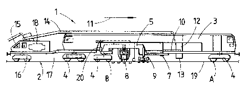
Fig. 1 shows a simplified side view of a tamping machine having a
satellite frame displaceable relative to a machine frame,
Fig. 2 shows an enlarged side view of a portion of the tamping
machine,
Figs. 3 and 4 each show a schematic representation of the tamping
machine with different tamping sections, and
Fig. 5 shows a greatly simplified side view of a further embodiment of a
tamping machine designed in accordance with the invention.
A machine 1, visible in Figs. 1 and 2, for tamping a track 2 has an elongated
machine frame 3 which is supported at its ends on the track 2 by means of
rail undercarriages 4. Provided between these two rail undercarriages 4
located at the ends is a satellite frame 5 which is supported, on the one
hand,
on the track 2 by means of a rail undercarriage 4 and, on the other hand, on
the machine

CA 02350166 2001-06-08
4
frame 3 with the aid of a joint 7. The satellite frame 5, equipped with a
tamping
unit 8 as well as a track lifting-lining unit 9, is displaceable relative to
the
machine frame 3 by means of a displacement drive 10.
Provided in front of the satellite frame 5 and behind the forwardly located
rail
undercarriage 4, with regard to the working direction of the machine 1
represented by an arrow 11, is a ballast chute 12 with outlet openings 13
positioned above the track 2. Furthermore, the machine 1 has a ballast
conveyor
14, extending in the longitudinal direction of the machine, by means of which
ballast may be transported from a rear machine end 15 to the ballast chute 12.
The rear machine end 15 is formed by a frame extension 17, supportable on a
rail undercarriage 16, which is equipped with a motor unit 18 and
articulatedly
connected to the machine frame 3.
A track lifting section 19, intended for lifting the track 2 for the track
position
correction and for tamping, is delimited, on the one hand, by the front rail
undercarriage 4 of the machine 1 and, on the other hand, by the rail
undercarriage 4 of the satellite frame 5. This track lifting section 19,
suited for
normal tamping, is denoted by points A and B in Figs. 1 and 3. As can be seen
in
particular in Fig. 2, the satellite frame 5 is connected in the region of its
rail
undercarriage 4 by means of a hydraulic drive 20 to guide rollers 21 which are
displaceably mounted on a guide 22, extending in the longitudinal direction of
the machine and connected to the machine frame 3. By means of the hydraulic
drive 20, the satellite frame 5 may optionally be lifted from a position of
being
supported on the track 2 into a position raised from the track 2 (see
Fig. 4).
The mode of operation of the machine 1 will be described in more detail below.
For the purpose of freshly ballasting the track 2, correspondingly large
amounts
of ballast are discharged via the ballast chute 12 onto the track 2. The
satellite

CA 02350166 2001-06-08
frame 5 is raised off the track 2 by actuation of the hydraulic drives 20 (see
Fig.
4). Thus, an extended track lifting section 19 is created, delimited by the
front
and the rear rail undercarriage 4 of the machine 1 and marked by A and C. In
this extended track lifting section it is now possible to lift the track to a
greater
height by means of the track lifting-lining unit 9, so that, along with the
increased
track lift, also larger amounts of ballast fall through the track onto the
ballast
bed. As soon as the desired amount of ballast is present underneath the track
2,
normal tamping can be carried out by supporting the satellite frame 5 on the
track 2 while releasing the hydraulic drives 20 (see Fig. 3). This causes an
automatic shortening of the track lifting section 19 to a length denoted by
points
A and B.
In Fig. 5, a machine 1 is shown in which the tamping unit 8 as well as the
track
lifting-lining unit 9 are fastened directly to the machine frame 3. The rear
rail
undercarriage 4 is displaceable by means of a drive 23 from a forward position
for normal tamping operation, represented in solid lines, into a rear end
position
(dash-dotted representation). With this, it is also possible to extend the
track
lifting section 19, if needed.

Dessin représentatif
Une figure unique qui représente un dessin illustrant l'invention.
États administratifs

2024-08-01 : Dans le cadre de la transition vers les Brevets de nouvelle génération (BNG), la base de données sur les brevets canadiens (BDBC) contient désormais un Historique d'événement plus détaillé, qui reproduit le Journal des événements de notre nouvelle solution interne.

Veuillez noter que les événements débutant par « Inactive : » se réfèrent à des événements qui ne sont plus utilisés dans notre nouvelle solution interne.

Pour une meilleure compréhension de l'état de la demande ou brevet qui figure sur cette page, la rubrique Mise en garde , et les descriptions de Brevet , Historique d'événement , Taxes périodiques et Historique des paiements devraient être consultées.

Historique d'événement

Description Date
Le délai pour l'annulation est expiré 2018-06-08
Lettre envoyée 2017-06-08
Accordé par délivrance 2005-08-09
Inactive : Page couverture publiée 2005-08-08
Inactive : Taxe finale reçue 2005-05-25
Préoctroi 2005-05-25
Un avis d'acceptation est envoyé 2005-05-05
Lettre envoyée 2005-05-05
Un avis d'acceptation est envoyé 2005-05-05
Inactive : Approuvée aux fins d'acceptation (AFA) 2005-04-05
Modification reçue - modification volontaire 2004-11-24
Inactive : Dem. de l'examinateur par.30(2) Règles 2004-08-04
Lettre envoyée 2002-05-13
Requête d'examen reçue 2002-04-10
Exigences pour une requête d'examen - jugée conforme 2002-04-10
Toutes les exigences pour l'examen - jugée conforme 2002-04-10
Demande publiée (accessible au public) 2001-12-09
Inactive : Page couverture publiée 2001-12-09
Inactive : CIB en 1re position 2001-08-09
Inactive : Certificat de dépôt - Sans RE (Anglais) 2001-07-11
Lettre envoyée 2001-07-11
Demande reçue - nationale ordinaire 2001-07-11

Historique d'abandonnement

Il n'y a pas d'historique d'abandonnement

Taxes périodiques

Le dernier paiement a été reçu le 2005-04-15

Avis : Si le paiement en totalité n'a pas été reçu au plus tard à la date indiquée, une taxe supplémentaire peut être imposée, soit une des taxes suivantes :

  • taxe de rétablissement ;
  • taxe pour paiement en souffrance ; ou
  • taxe additionnelle pour le renversement d'une péremption réputée.

Les taxes sur les brevets sont ajustées au 1er janvier de chaque année. Les montants ci-dessus sont les montants actuels s'ils sont reçus au plus tard le 31 décembre de l'année en cours.
Veuillez vous référer à la page web des taxes sur les brevets de l'OPIC pour voir tous les montants actuels des taxes.

Titulaires au dossier

Les titulaires actuels et antérieures au dossier sont affichés en ordre alphabétique.

Titulaires actuels au dossier
FRANZ PLASSER BAHNBAUMASCHINEN-INDUSTRIEGESELLSCHAFT M.B.H.
Titulaires antérieures au dossier
HERBERT WORGOTTER
JOSEF THEURER
Les propriétaires antérieurs qui ne figurent pas dans la liste des « Propriétaires au dossier » apparaîtront dans d'autres documents au dossier.
Documents

Pour visionner les fichiers sélectionnés, entrer le code reCAPTCHA :


Pour visualiser une image, cliquer sur un lien dans la colonne description du document (Temporairement non-disponible). Pour télécharger l'image (les images), cliquer l'une ou plusieurs cases à cocher dans la première colonne et ensuite cliquer sur le bouton "Télécharger sélection en format PDF (archive Zip)" ou le bouton "Télécharger sélection (en un fichier PDF fusionné)".

Liste des documents de brevet publiés et non publiés sur la BDBC .

Si vous avez des difficultés à accéder au contenu, veuillez communiquer avec le Centre de services à la clientèle au 1-866-997-1936, ou envoyer un courriel au Centre de service à la clientèle de l'OPIC.

({010=Tous les documents, 020=Au moment du dépôt, 030=Au moment de la mise à la disponibilité du public, 040=À la délivrance, 050=Examen, 060=Correspondance reçue, 070=Divers, 080=Correspondance envoyée, 090=Paiement})


Description du
Document 
Date
(aaaa-mm-jj) 
Nombre de pages   Taille de l'image (Ko) 
Dessin représentatif 2001-11-12 1 10
Abrégé 2001-06-07 1 14
Description 2001-06-07 5 213
Revendications 2001-06-07 1 51
Dessins 2001-06-07 2 39
Description 2004-11-23 5 210
Abrégé 2004-11-23 1 10
Revendications 2004-11-23 1 40
Dessin représentatif 2005-07-28 1 10
Courtoisie - Certificat d'enregistrement (document(s) connexe(s)) 2001-07-10 1 112
Certificat de dépôt (anglais) 2001-07-10 1 163
Accusé de réception de la requête d'examen 2002-05-12 1 179
Rappel de taxe de maintien due 2003-02-10 1 106
Avis du commissaire - Demande jugée acceptable 2005-05-04 1 162
Avis concernant la taxe de maintien 2017-07-19 1 178
Taxes 2003-04-06 1 35
Taxes 2004-04-14 1 35
Taxes 2005-04-14 1 37
Correspondance 2005-05-24 1 35