Note: Descriptions are shown in the official language in which they were submitted.
CA 02350292 2001-06-13
Attorney Docket No. 482.82
IN THE UNITED PATENT AND TRADEMARK OFFICE
Title: WATER PURIFYING APPARATUS
Inventors: Charles F. Fritter, Shrirang P. Netke, Jonathan E. Scruggs III, and
Stefan A.
Groess
lo BACKGROUND OF THE INVENTION
1. Field of the Invention
The present invention relates to venting of gasses from fluids, and in
particular, venting of gasses
from filter elements or filter media used in water treatment devices.
In particular, this invention relates to a multi-stage filter cartridge that
incorporates a fluid flow
diverter to vent air from an interface between stages of the filter cartridge.
Major categories of domestic point-of-use (POU) systems include: a) plumbed-in
or faucet-
mounted systems that rely on the pressure of the water supply as the driving
force for filtration,
and b) non-plumbed pour-through or batch systems that rely on gravity to force
water from an
upper influent water chamber, through a filtering means and down to a lower
effluent water
chamber.
Typical POU systems known in the art employ various combinations of
purification agents that
remove contaminants by chemical or physical means. These purification agents
may be present
in forms such as, but not limited to porous, non-porous, granular, fibrous,
filamentous or
particulate. Examples of these purification agents include zeolites, ion
exchange resins, activated
carbons and mechanical filtration medias. Such agents remove contaminants from
water through
processes such as adsorption, chemical reaction and size exclusion. The use of
such purification
agents can result in air entrapment within filter cartridges because some
agents are hydrophilic
("water-loving") and therefore air-impervious. Since the pressure available to
a gravity driven
filtration system is typically 1.0 pounds per square inch (PSI) or less, air
trapped within the filter
cartridge is unlikely to be forced out with the effluent water. But rather,
because of its buoyancy,
air tries to move upward through the cartridge. However, when the air
encounters a wetted
CA 02350292 2009-07-14
purification agent with a hydrophilic nature, it becomes trapped due to
surface tension at the
air/liquid interface.
A typical gravity driven system which has an upper reservoir, a filter, and a
lower filtered water
collection chamber is described in US patents 4,895,648 and 4,969,996, both to
Hankammer,
Thus, one problem to be overcome in designing filter cartridges for gravity-
driven POU systems
is the venting of air from the cartridge. During normal use of such
cartridges, air is often trapped
inside. This is particularly true for multi-stage filters where several
purification agents of
differing hydrophilicities are used. This trapped air can cause many problems
including
preventing the filter cartridge from functioning at maximum flow rate, causing
channeling of the
filtering water, or even result in filter lock-up where no water is flowing at
all. When such a filter
is new, air originally within the filter before use must be vented, and any
time water flow
through the filter cartridge is interrupted, accumulated air may need to be
vented.
Examples of venting strategies are known in the art. Saito (US5225079) and
Kawai
(US4772390) both employ air-pervious, water-impervious membranes through which
the trapped
air is vented while at the same time preventing filter leakage. However, this
strategy requires the
relatively higher pressure of a plumbed-in or faucet-mounted filtration system
to efficiently vent
the trapped air in a reasonable amount of time. Hankammer (US4895648) teaches
the use of a
filter cover connected to a hollow tube that vents air from the top of the
single stage or
component filter. However, this method has three disadvantages: it only vents
air that manages to
rise to the top of the filter cartridge and cannot vent the air trapped near
the bottom of the
cartridge, the filter cover is external to the filter cartridge and thus can
be inadvertently removed
or lost by the user, and since this filter cover resides in the upper influent
water chamber, water
can enter the opening in the filter cover tube, block the air release ports at
the top of the filter
cartridge lid by surface tension, and cause filter lockup.
2
CA 02350292 2006-10-11
SUMMARY OF THE INVENTION
The present invention provides a means of venting air trapped at the bottom of
the filter
cartridge and unable to rise to the top, or which is internal to the filter
cartridge. The
structural configuration of the venting structure is such that it cannot be
inadvertently
blocked by the surface tension of water. The vent structure has utility in any
apparatus
wherein a gas is or becomes entrained or mixed with a fluid, and in particular
where such
gas may impede, slow or interfere with fluid flow, or where it is desirable to
removes gases
for any reason. In particular, a multi-stage filter having two or more
filtration systems,
arranged axially along the fluid flow path, results in an interface between
stages which may
generate, entrap or entrain air or gases within the fluid.
In particular, the vent structure is useful in systems having a pressure drop
of 1 psi or less,
such as those systems which filter a fluid by a pressure differential
generated by gravity
alone, or aided by a manual pressurization means. Pressure drop can be
measured directly
with a gauge, or can be calculated by measuring the vertical height of the
water column
across the structure to which the pressure drop applies.
As used herein the term "fluid communication" means a path by which liquids or
gases
may move between two or more structures. The term "liquid communication" means
a path
by which liquids may move between two or more structures. The term "multi-
stage" means
two or more stages. The term "potted" means fixing or sealing hollow fiber
bundles to hold
them in place and to provide a defined fluid flow pathway. Also as used
herein, air and
gases are used interchangeably, unless otherwise apparent from the context.
In another aspect, the present invention provides a gravity-fed fluid filter
comprising: a
housing having at least one fluid entry port and at least one filtered fluid
exit port; a first
filtration medium disposed intermediate to said fluid entry port and filtered
fluid exit port; a
second filtration medium disposed intermediate to said first filtration medium
and said
filtered fluid exit port; and a venting system disposed intermediate to said
first and second
filtration media, said venting system including a tangential fluid diverter
configured and
arranged to separate a fluid flow into a first region of liquid flow and a
second region of
3
CA 02350292 2006-10-11
non-liquid flow to thereby vent gases therefrom, said gasses being vented
countercurrently
to said fluid flow whereby an air-to-air interface is maintained.
BRIEF DESCRIPTION OF THE DRAWINGS
Fig. 1 is a perspective view of a filter cartridge of the present invention;
Fig. 2 is an exploded elevational view of the filter cartridge of Fig 1;
Fig 3 is an elevational view of the filter cartridge of the present invention,
as installed in a
pitcher;
3a
CA 02350292 2001-06-13
Attorney Docket No. 482.82
Fig 4 is a magnified, sectional view of a portion of the filter cartridge of
the present invention
showing fiber loops;
Fig 5 is a close-up, cut away, elevational view of the filter cartridge of Fig
1;
Fig 6 is a perspective view of a lower portion of the reservoir of Fig 3,
showing the means for
securing the filter cartridge to the pitcher reservoir; and
Fig 7 is an idealized schematic side elevational view of fluid flow through
the filter of the
present invention.
It is an object of the present invention to provide an improved water-
purifying apparatus of the
io type mentioned above which will achieve a maximum of hygiene, especially as
regards
elimination of unwanted germs, and an improvement in sealing.
It is another object of the present invention to provide a multi-stage fluid
filtration apparatus
which facilitates a fluid flow by mitigating or eliminating air entrapment
between stages.
It is another object of the present invention to provide a means for venting a
fluid treatment
device or apparatus to promote fluid flow.
It is yet another object of the present invention to provide a low pressure
water treatment
apparatus, which removes microbiological contaminants while providing a
consumer-acceptable
flow rate.
It is yet another object of the present invention to provide a gravity-fed
water filter which
reduces inorganic contaminants, improves taste and odor, and removes or
reduces
microbiological contaminants.
It is a further object of the present invention to provide a two chambered,
gravity fed filter
apparatus which filter which may be inserted from a lower chamber.
The invention further relates to a gravity-fed filter apparatus adapted for
removal of
microbiological contaminants, characterized by a flow rate of at least 30 cm3
per minute.
4
CA 02350292 2001-06-13
Attorney Docket No. 482.82
These and other objects and advantages of the present invention will no doubt
become apparent
to those skilled in the art after reading the following Detailed Description
of the Preferred
Embodiments.
DETAILED DESCRIPTION OF THE PREFERRED EMBODIMENTS
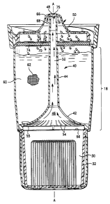
As illustrated in Figs I and 2, there is a fluid treatment cartridge 10 of the
present invention. The
cartridge 10 includes, generally, an outer housing or shell 12, a lower
filtration module 30, a vent
i o element 40 and filter cap 50. The cartridge 10 comprises an outer housing
or shell 12, having a
lower filtered water outlet 14, and sealing skirt 16. The housing 12 has a
generally hollow
interior defining a cavity 18. The filter cartridge 10 is designed and adapted
to be utilized with a
pitcher 20 (shown in Fig 3) having an unfiltered water reservoir 22, and a
filtered water chamber
24. Referring again to Figure 2, the lower filtration module 30 occupies a
lower portion of the
cartridge 10. In one embodiment of the cartridge 10, the module 30 comprises a
housing 32
within which is plotted a plurality of hollow fiber filtration elements 34.
Such hollow fiber filter
elements 34 may be made of a polymeric material made from monomers such as
ethylene,
propylene, sulfone, ethersulfone, vinylpyrrolidone and mixtures thereof, or
other materials
known to the art. Furthermore, the lower filtration module 30 may be integral
to or part of a
corresponding portion of the cartridge 10 such that the module housing 32 is
omitted. For
example, a plurality of hollow fiber filters elements 34 may be potted
directly within the housing
12 of cartridge 10. The lower filtration module 30 may also comprise other
filtration media,
such as disk or pleated membranes or particulate media, or combinations of
media. Such media
function by removing unwanted constituents from the fluid; or may act upon the
unwanted
constituents to change them physically, chemically or biologically to a more
desirable (or less
undesirable) form; or may add a beneficial constituent.
The use of such purification agents can result in air entrapment within filter
cartridges because
some agents are hydrophilic ("water-loving") and therefore air-impervious.
Since the pressure
initially available to a gravity driven filtration system is typically 1.0
pounds per square inch
(PSI) or less, air trapped within the filter cartridge is unlikely to be
forced out with the effluent
5
CA 02350292 2001-06-13
Attorney Docket No. 482.82
water. Rather, because of its buoyancy, air tries to move upward through the
cartridge.
However, when the air encounters a wetted purification agent with a
hydrophilic nature, it
becomes trapped due to surface tension at the air/liquid interface. This
trapping of air is even
more likely to occur in gravity driven systems wherein when the available
pressure differential
diminishes due to a diminished column or head of water in the reservoir.
Within the lower filtration module 30, the hollow fiber elements 34 are
preferably arrayed in the
form of loops 35, as depicted in Fig. 4. The loops 35 have formed therein a
plurality of surface
apertures 36 which may range in diameter from about 0.01 to 3 microns. Each
loop 35 has two
io terminal apertures 37, which permit filtered fluid to exit the fiber 34.
Referring to Fig. 4, fluid thus flows from outside the hollow fiber element
34, through the
surface apertures 36 and out of the terminal apertures 37. The surface
apertures 36 are selected
to be smaller than the size of the unwanted contaminant, such that the
contaminant, e.g. a
microbe or cyst, is filtered out of the fluid. Additionally, flow rates are
optimized when the
fibers are arrayed in rows having 0.01 mm or greater spacing therebetween to
allow release of air
or gases trapped between fibers. Examples of spacing geometries in a
cylindrical module
configuration include concentric rings, or a spiral of fiber bundles. Examples
of other
configurations include horizontally, vertically or angled fiber arrays which
may be regular or
irregular and having fibers with one or both open ends. A hollow fiber can be
conceptualized as
a membrane filter, in that it operates by excluding unwanted contaminants from
the interior of
the fiber, by virtue of the small size of the apertures 36. A hollow fiber
bundle thus presents a
membrane surface having very great total surface area to expose the unfiltered
fluid. The
module 30, in one embodiment contains fiber bundles having a surface area of
about 0.08-
0.15m2 . As is known to the art, a fluid flow path can be inside-out or
outside-in.
In another embodiment of the present invention, fluid flow through the hollow
fiber bundles is
further enhanced by treating the fiber elements 34 with a surfactant or
surfactants. The
surfactant treatment acts to increase the hydrophilicity of the fibers, and
results in faster flow
rates with less pour-to-pour variation in flow. The manner of fiber treatment
is not critical; the
fiber bundles can be soaked in aqueous solutions of surfactant, or such
solutions can be run
through the fiber bundles. In either case, the treatment may be performed
singly, or repeatedly.
6
CA 02350292 2001-06-13
Attorney Docket No. 482.82
Most preferably, a rinse solution, especially water, follows the treatment. A
single surfactant or
a mixture of surfactants can be used, and preferably a mixture of nonionic
surfactants. Such
surfactants may be polyethoxylated alcohols, sulfonates, or sulfates. It has
been found, however,
that use of a polyvinyl alcohol surfactant does not provide consistent,
consumer acceptable flow
rates at the operable pressures of gravity-fed pitcher systems, i.e about 0.3
psi or less.
Referring to Figure 5, within the cavity 18, and above the lower filtration
element 30 there is a
space defining a primary filter media chamber 60. This chamber 60 may be
filled, or partially
filled with a variety of filtration media 62 to yield a first filtration
element acting as a first stage
filter. Preferably, the chamber 60 contains a granular activated carbon, an
ion exchange material,
or a mixture thereof. Optionally, bacteriostatic material such as silver,
copper, zinc or materials,
which kill or inhibit bacteria through oxidation/reduction may be included
with one or more of
the filter media 62.
The vent element 40 comprises a tangential fluid diverter 42, a vent tube 44,
a lower air
collection space 46 and an upper vent port 48. The vent tube 44 includes a
central aperture 52 to
permit the free passage of air or gases from the lower air collection space 46
therethrough, and to
exhaust through the upper vent port 48. The tangential fluid diverter 42
includes a plurality of
openings 54 spaced circumferentially thereabout, through which water may flow.
The geometry
of the openings 54 is not critical and they may be circular, oblong or slot-
like, for example and
may be spaced regularly, or irregularly. A lower surface 55 of the tangential
fluid diverter 42 is
in proximity to or abutting an upper intake surface 56 of the fine filtration
module 30. It can be
seen that the vent element 40 occupies a portion of the central chamber 60
which is otherwise
filled with the filter media 62. In one embodiment, the vent tube 44 extends
upwardly through a
central axis AA of the filter cartridge 10, however a variety of geometries
are possible and within
the scope of the present invention. The vent element 40 need not be a discrete
structure but all or
part thereof may be formed by other structures within the filter 10. For
example, the filter media
62 may include or comprise a self supporting carbon, plastic or mixture
thereof, which would
permit all or part of the vent element 40 to be formed by void space within
the media 62. In such
a case supplemental structure could be added as necessary to achieve the
desired result. The
7
CA 02350292 2001-06-13
Attorney Docket No. 482.82
filter medium could also be modified to achieve the desired flow
characteristics, i.e. by selective
addition of additives to the media, or by inclusion of structural elements.
The vent element 40 provides a means of venting air or gases countercurrently
to a flow of water
or other fluid. As implemented for a gravity fed water filtration pitcher of
the type depicted in
Fig 3, the fluid is water and the vented gas is air, which is vented upwardly
while water flow is
downward throughout the filter 10.
The tangential fluid diverter 42 is generally in the form of an inverted
funnel cone, or conic
lo section which viewed in cross-section, is angled from five to eighty-five
degrees relative to the
vertical. The tangential fluid diverter 42 is preferably radially symmetrical.
Viewed in cross
section, the tangential fluid diverter may be conical, frustro-conical,
polyhedral, tetrahedral,
pyramidal, parabolic, hyperbolic, inversely parabolic and inversely
hyperbolic. The surface may
be linear, convex curved, concave, or some combination thereof. A variety of
shapes are
suitable as long as the surface of the tangential flow diverter 42 changes the
fluid flow vector
from vertical to one having some horizontal component. Multiple curves are
also suitable as
long as the surface imparts an inward component, i.e. along line V,, (depicted
in Fig 7), to the
direction of the water flow.
In another embodiment of the vent element 40 the apertures 54 are angled
and/or curved to
impart a circular or swirling motion to the fluid as it passes therethrough.
Such circular or
swirling motion also results in turbulent flow, and the release of entrained
air. Additionally,
circular flow may be imparted by the use of vanes (not shown) positioned on
the inner surface of
the tangential fluid director 44, or on the inner surface of the lower
filtration module 30. Such
vanes could be either flat or curved and would be positioned to deflect fluid
inwardly and/or to
induce rotational flow.
Refemng again to Figs. 2 and 5, the filter cap 50 seals the cartridge 10 about
an upper surface 64
thereof. The filter cap 50 includes an inner sealing surface 65 and a vent
cone 66 at the highest
portion thereof. Below the vent cone 66 there is formed into the cap so one or
more apertures
68, through which air can escape during the venting process. Filter cap 50
further includes a
8
CA 02350292 2001-06-13
Attorney Docket No. 482.82
plurality of water inlets 70 formed therethrough. In one embodiment, a scrim
or containment
medium 74 is positioned intermediate to the filter cap 50 and the filter media
62, and acts to
retain fines from the media 62. The scrim 74 may be woven or non-woven
material, such as a
polyester, or a polyolefin, or a polyolefin treated to be hydrophilic, as is
known in the art, or the
scrim 74 may be omitted entirely.
In operation, water flows from the pitcher reservoir 22 under the influence of
gravity (or aided
by some other source of pressure) through a plurality of the water inlets 70
of the filter cap 50
thence entering cavity 18 filled with primary filtration media 62. Water flows
through the
l o primary filtration media 62 and impinges upon the tangential fluid
diverter 42. As the flow of
fluid passes through the openings 54, it is translated from an essentially
vertical flow to one
which has a horizontal component as represented by V,, in Figure 7. The
tangential fluid
diverter 42 separates the flow into two regions: a first region of liquid flow
at the outer area of
the fluid diverter 42 and a second region of non-liquid flow proximal to the
lower air collection
space 46, wherein air is collected. The geometry of the fluid diverter 42
effectively floods the
lower stage with liquid, thus forcing the air to the region of non-liquid flow
at the lower air
collecting space 46 within the center of the cone formed by the fluid diverter
42. The collected
air is forced, by the (static) pressure of the water column in the space 60,
from the air collecting
space 46, up the aperture 52, exiting at vent port 48. The air exiting the
vent port 48 is trapped
under the vent cone 66 and forced out the aperture(s) 68 by the pressure
induced by the
impinging fluid. As shown in Fig. 5, a space 75 is formed immediately under
the vent cone 66
and above the vent port 48. This space 75 acts to maintain an air-to-air
interface extending from
the space 75, through the aperture 52 of the vent tube 44 and into lower air
collecting space 46.
Such air-to-air interface facilitates the venting or removal of air or gasses
from within the filter
10 by equalizing gas (air) static pressure to ambient pressure, permitting in
free flow of fluid
(water) downward through the filter 10.
Referring to Figs. 4 and 5, the spaces formed between fiber loops 35 can trap
air, resulting in
bubbles which then impede the flow of fluid through the fiber, initially
diminishing the flow rate
of the system. As additional fluid enters the system, fluid pressure builds up
and, the static
pressure of the fluid will force the air bubble upwards through the aperture
52 of the vent tube
9
CA 02350292 2001-06-13
Attomey Docket No. 482.82
44, eliminating the disadvantage inherent in a counter current flow of air and
water. The flow of
fluid becomes turbulent as it passes through the apertures 54 and the
turbulent flow acts to
release entrained gases, which then collect in the lower gas collection space
46 of the vent
element 40.
Figure 7 is an idealized two-dimensional schematic of fluid flow through the
tangential flow
diverter 42 of the vent element 40. It can be seen that in region a, (the area
of the cylinder
defined by the filter housing 12, less the area occupied by the vent tube 40)
the Nonnal direction
of fluid flow Vy is parallel to the vent tube 40 and side walls 12, or with
reference to the filter 10,
downward. This fluid flow has a velocity V, imparted by the acceleration of
gravity. At the
surface of the flow diverter 42, the cross-sectional area for fluid flow is
reduced to a2 . The
decreased cross-sectional area results in increase in velocity to V2, in
accordance with
Bernoulli's principle. In the region defined by a2, the fluid flow is
streaming, i.e. it exhibits
altered direction and velocity. As water level rises, the horizontal component
of fluid flow i.e.
V,, increases which has the effect of compressing air trapped within the air
collecting region 46
and urging it out the vent tube 44.
ln one embodiment of the upper reservoir 22 of the pitcher 20 to which the
filter 10 attaches
depicted in Figure 6, there is an annular skirt 80 fonned into a lower portion
of the upper
reservoir 22 of pitcher 20. The annular skirt 80 is constructed and arranged
to mate with the
corresponding skirt 16 of the filter 10 to provide a fluid tight seal. Within
the periphery of the
annular skirt 80 there are a plurality of radially arranged apertures 84
formed through the
reservoir 22 to permit the free passage of fluid downward therethrough. In an
alternative
embodiment of the filter 10, there is at least one aperture 68 formed near or
at the top of the filter
cap 50, preferably formed to be directly above the central aperture 52 of the
vent tube 44. In this
embodiment the air-to-air interface is maintained by an annular airlock skirt
86, (shown in
phantom in Fig. 6), formed into a lower surface of the reservoir 22 and
coaxial with the annular
skirt 80. When the filter 10 is secured to the reservoir 22, in this
embodiment the annular airlock
skirt 86 is positioned and configured to overlay the air aperture 68 to define
an airlock
therebetween. Air from the annular airlock skirt 86 is thus permitted to exit
unimpeded around
the periphery of the airlock skirt 86, and may be aided by a notch 87 form
therein.
CA 02350292 2001-06-13
Attorney Docket No. 482.82
The sealing skirt 16 includes structure known in the art for securing two
objects, either
permanently, or releasably, that is, the sealing skirt 16 preferably permits
repeated locking and
unlocking of the filter cartridge 10 to corresponding skirt 80 of the
reservoir 22. In one
embodiment, the sealing skirt 16 includes threads 102, which cooperate with
threads 104 of the
filter 10, as illustrated in Figs. I and 6. Alternative structures may
comprise a bayonet type
mount, pin and track, compression fit or a magnetic mounting.
Since the filter 10 is intended to remove microbiological contaminants, it is
important to
maintain microbiological integrity of the connection between the filter 10 and
reservoir 22.
Furthermore the reservoir 22 and filter 10 are designed so that the filter 10
is secured to the
reservoir 22 by attaching the filter 10 to the annular skirt 80 from a bottom
or lower surface, as
depicted in Figs. 3 and 6. This is to be contrasted with systems where the
filter 10 is inserted
from an upper surface of the reservoir 22 through an aperture sized to permit
the filter 10 to pass
therethrough, for example as disclosed in U.S. 4,969,996. In the former
systems, filter size is
dictated by the dimensions of the aperture through which the filter is
inserted, and by the
distance from the reservoir bottom to the bottom of the pitcher. Because the
filter 10 of the
present invention does not have to pass through an aperture in the reservoir
22, the filter 10 is not
limited in size, for example in diameter. Further the diameter of the filter
may vary, as from top
to bottom, such that the top is larger in diameter than the bottom or vice
versa. This makes it
possible to improve filter performance, longevity, features and or aesthetics
by modifying filter
size as needed. Additionally, the attachment means of the filter 10 of the
present invention
allows for a variety of filter orientations besides purely vertical. Thus the
filter may be inclined
or fully horizontal. A significant benefit afforded by the horizontal
arrangement is that the filter
can be configured to lay flat on the bottom of a gravity-fed pitcher, thus
maximizing the pressure
head available to force water therethrough. In this instance, the filter would
be in fluid
communication with the reservoir through some intermediate coupling means.
11
CA 02350292 2001-06-13
Attorney Docket No. 482.82
It is to be noted that the benefits afforded by the venting structures
described herein are not
limited to those filters, which attach in the manner described above. Rather,
the venting structure
can provide advantages to filters regardless of means of attachment to the
reservoir, or
orientation within the pitcher.
EXPERIMENTAL
Table 1 is a comparison of flow time (in seconds) of a two stage water
filtration module,
unmodified, with the vent element 40 in place, and with the vent element 40
plus a surfactant
treatment of the hollow fibers. In all cases, the hollow fiber module was a
commercially
lo available module manufactured and sold by Mitsibishi Rayon Co., Ltd., under
the trademark KC-
140. The fiber loops were polyethylene, and had a total surface area of 0.15
m2. One liter of
water was poured thorough the filter, and at least ten repetitions were done
for each filter
condition. It can be readily seen that the mean flow times without the vent
element are about
double those for the filter with the vent element, and nearly four times
greater than those with the
vent element and surfactant treatment. Further, the standard error decreases
sharply for the
filter with the vent element and surfactant treatment. This demonstrates the
consumer-
perceivable benefit of consistency in rapid water pour-through.
12
CA 02350292 2001-06-13
Attorney Docket No. 482.82
TABLE I
Mean Flow Time (sec) Standard Error
Hollow Fiber Alone 1296 12.5
Hollow Fiber plus Vent 683 12.4
structure
Hollow Fiber, Vent 488 6.9
structure, surfactant
treatment
In the table above, the modules used for the tests described in the first and
second rows were
polyethylene hollow fiber, manufactured by Mitsubishi Rayon, pretreated with a
vinyl
alcohol/vinyl acetate copolymer.
The surfactant treatment of the present invention (the third row of Table I
above) comprised an
average of the following two methods:
Method 1. Each filter module was soaked for five minutes with agitation in a
solution that was a
mixture of 0.5% of each of two nonionic surfactants. The modules were then
rinsed thrice
successively by soaking for five minutes with agitation in clean tap water.
Method 2. The membrane modules were mounted inside sealed filter housings, and
1 liter of a
mixture of 0.5% of each of two surfactants was allowed to pass through at a
rate of 10 minutes
per liter. The modules were then rinsed thrice successively by passing through
I liter of clean tap
water at a rate of 10 minutes per liter.
The nonionic surfactants were an extoxylated alcohol having an alkyl chain
length averaging 11
carbons and about 5 moles of ethylone oxide per molecule, for example a Neodol
1-5, marketed
by the Shell Chemical Company and a sulfate surfactant having a 10-12 carbon
alkyl group with
an average of 6 moles of ethylene oxide per molecule, sold by the Texaco
Chemical Company
under the trademark Surfonic L12-6.
13
CA 02350292 2001-06-13
Attorney Docket No. 482.82
After either treatment method, the modules were allowed to air dry after which
they were ready
for use.
While described in terms of the presently preferred embodiment, it is to be
understood
that such disclosure is not to be interpreted as limiting. Various
modifications and
alterations will no doubt occur to one skilled in the art after having read
the above
disclosure. Accordingly, it is intended that the appended claims be
interpreted as
covering all such modifications and alterations as fall within the true spirit
and scope of
the invention.
14