Note: Descriptions are shown in the official language in which they were submitted.
CA 02350448 2005-10-05
LASER IMAGING WITH VARIABLE PRINTING SPOT SIZE
The present invention relates to a device and method for the spotwise
imaging of printing surfaces with the aid of at least one beam which is
moved relative to the printing surface.
During the imaging of printing plates in CtP (computer-to-plate) or direct-
imaging printing press, the spacing between the printing surfaces and the
optical system of the imaging device has to be maintained very accurately
to obtain an optimum result. However, deviations from the intended
distance between the printing surface and the imaging laser arise, for
example, because of oscillations of the machine during operation. The
extent to which the quality of the imaging result depends on the deviation
from the intended distance is determined, inter alia, by the beam quality of
the laser and the selected beam parameters. A deviation from the
intended distance generally gives rise to a deformed printing spot which is
either larger or smaller than the predefined nominal size results form,
depending on the beam parameters. In the case of very large deviations,
even no printing spot is generated at all on the printing surface because
the laser beam is widened to such an extent that the imaging threshold is
no longer reached at any location of the printing surface.
U.S. Patent No. 5,764,272 discloses an autofocus system for a laser
imaging device. This system has a laser and a corresponding optics for
forming a light beam which is focused on an image plane. Via a
photodiode, a signal which is characteristic of the light reflected from the
image surface is generated so that the focus of the laser beam on the
image surface can be correspondingly adapted to the characteristic signal.
In this manner, a close association of the image surface and the image
plane of the laser including its corresponding optics is brought about. For
shifting the focus of the imaging device, it is possible to move the laser,
the corresponding optics or the image surface.
Autofocus systems of this kind can work only at limited speeds. For
example, if the laser optics is moved, it is required for a mass that is not
negligible to be quickly accelerated, accurately positioned, and quickly
CA 02350448 2005-10-05
decelerated again. For high-frequency disturbances such those that arise,
for example, due to dirt accumulations under the printing surfaces, dust
particles or because of folds in the printing surface, the control times
needed by such a system are too long. Therefore, imaging defects occur
frequently. In a multichannel system, i.e., an imaging device having a
plurality of parallel laser beams, it is typically not possible to focus each
individual beam since the whole imaging optics is moved. In other words:
a comprise must be found so that the deviation from the intended distance
of all simultaneous beams altogether becomes minimal. Generally, the
design of a mechanical autofocus system which functions by moving the
imaging optics requires considerable technical outlay, a corresponding
constructional space, and causes a relatively great expense.
Therefore, it would be desirable to provide a device for the spotwise
imaging of printing surfaces with the aid of at least one laser beam which
is moved relative to the printing surface and which makes it possible to
carry out a variable imaging without having to mechanically move parts of
the device such as the imaging optics to compensate for variations in the
distance between the imaging optics and the printing surface.
A device for spotwise imaging printing surfaces according to the present
invention comprises a laser light source producing at least one laser beam
movable relative to a printing surface, the laser beam defining an image on
the printing surface, the laser light source having an input laser power; and
a laser control varying the input laser power or an exposure time as a
function of a distance of the laser light source from the image spot; and a
distance meter for determining the distance of the laser light source from
the image spot.
According to an aspect of the invention the laser light source includes a
diode laser.
In an aspect of the invention the laser light source produces a plurality of
light beams spatially separated from one another for simultaneous imaging
of a plurality of printing spots.
2
CA 02350448 2005-10-05
In a preferred aspect of the invention the laser light source includes an
individually controllable diode laser array.
A method for imaging printing surfaces using light according to the present
invention comprises the steps of providing a laser light source for
generating a laser beam having a position-dependent intensity distribution
in two spatial directions perpendicular to a propagation axis, and a specific
divergence; providing a printing surface at a distance from the laser light
source; measuring the distance of the laser light source from the printing
surface; exposing the printing surface located at a certain distance from
the laser light source and varying an input laser power or exposure time so
as to vary a spot size of image spots on the printing surface, wherein the
varying of the laser power or exposure time is a function of the distance of
the laser light source from the image spot on the printing surface.
A method for generating printing spots of desired size according to the
present invention comprises the steps of providing a laser light source for
generating a laser having a position-dependent intensity distribution in two
spatial directions perpendicular to a propagation axis, and a certain
divergence; providing a printing surface at a distance from the laser light
source; measuring the distance of the laser light source from the printing
surface; adjusting the spot size to a predetermined value by varying the
input laser power or exposure time, wherein the varying of the laser power
or exposure tine is a function of the distance of the laser light source from
the image spot on the printing surface.
The imaging optics of an imaging device is typically adjusted in such a
manner that, at the intended distance, the focus, i.e., the plane in which
the laser beam has its smallest diameter comes to rest exactly on the
surface of the printing surface. A deviation from the intended distance
between the laser and the printing surfaces results in an increase in the
beam diameter on the printing surface and consequently, in an increase or
reduction in size of the printing spot, depending on the adjustment of the
laser parameters of power and focus
2a
CA 02350448 2001-06-13
A-2890
diameter. The actual distance between the printing surface and the laser is
measured by means of a detector so that it can be compared to a setpoint
value.
The optical power used for imaging is increased or reduced as a function of
the
deviation from the setpoint value. An increase in the laser power is
associated
with an increase in size of the printing spot since the spot size on which
energy
exceeding the imaging threshold is deposited on the printing surface
increases.
Correspondingly, a reduction in the laser power is associated with a reduction
in
size of the printing spot since the spot size on which energy exceeding the
imaging threshold is deposited on the printing surface decreases.
A further way of varying the size of the printing spot is to selectively
prolong or
shorten the exposure time. A combination of the change in the power and in the
exposure time is also possible.
Using the device according to the present invention, the increase or reduction
in
size of the printing spot due to a deviation in distance can be compensated
for:
via the provided variable laser power, it is possible to adapt the printing
spot size
so that an acceptable imaging result is attained. In other words: the printing
spot
size is variable. The value of the required optical power or exposure time can
be
computed from the measured distance. This function can be carried out, for
example, in the raster generator which converts the printing spot pattern to
be
imaged into a time sequence of pulses for the laser imaging. In an
advantageous
manner, a table, a so-called ~°lookup table", is prepared and stored in
the
preliminary stages via the functional relation so that the required value is
immediately available in situ.
In an advantageous refinement of the present invention, the device for the
spotwise imaging of printing surfaces has a plurality of laser beams which are
used for simultaneous imaging. In this context, in particular individually
controllable diode laser arrays are given preference. The power or the imaging
time can be varied for each individual laser of the array, making it possible
to
attain an acceptable imaging result since the size of each printing spot
written by
a laser is variable and independent of the size of the other printing spots.
3
CA 02350448 2001-06-13
A-2890
The present invention requires considerably fewer moving parts than the known
autofocus systems and can therefore react much more quickly to disturbances.
At the same time, it attains a markedly better imaging result than a device
without autofocus. The implementation of compact imaging devices in an
integrated form is markedly easier. It involves lower cost.
A device of this kind can be used inside or outside of a printing unit or a
printing
press for spotwise imaging.
Further advantages and expedient embodiments of the present invention will be
described on the basis of the following Figures and their descriptions.
Specifically,
Figure 1 shows the variation in the spot size of a laser beam;
Figure 2 shows the generation of a printing spot on a printing surface
by moving a laser beam relative to the printing surface;
Figure 3 shows examples of written printing spots with different laser
parameters;
Figure 4 shows a schematic view of the imaging of a printing surface
using a device according to the present invention.
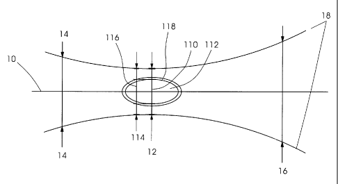
Figure 1 shows the variation in the spot size of a laser beam for the spotwise
imaging of printing surfaces. The laser beam propagates along optical axis 10
on
which, in addition, its intensity maximum is located. In focus 12, the laser
beam
has its smallest waist. An imaging is advantageously carried out at this
point. In
other words: focus 12 defines the intended distance of the laser from the
printing
surface. Both at a point 14 in front of the focus and at a point 16 behind the
focus, the beam is widened. Lines 18 indicate the variation in the boundary of
the
4
CA 02350448 2001-06-13
A-2890
light spot as a function of the position along the propagation direction. In
focus
12, a greater intensity than the threshold intensity for imaging is reached in
a
region 110. Because of the widening of the laser beam in front of and behind
focus 12, the region in which the intensity exceeds the threshold intensity
becomes smaller since the conveyed energy flows through a larger
cross-sectional area. Thus, if the laser intensity is maintained, region 112
results
in which the imaging threshold is exceeded. In case of a shortened actual
distance 114 from the laser to the printing surface, region 116 to be imaged
is
larger than region 112 attained with maintained intensity. According to the
present invention, the intensity of the laser is consequently increased so
that the
region in which the threshold intensity for imaging is exceeded increases. The
threshold intensity is then exceeded in the whole region 118. At actual
distance
114, the threshold intensity is then reached in the whole region 116.
Fig. 2 shows the generation of a printing spot by moving a laser beam relative
to a
printing surface. A laser beam impinges on a printing surface 20 with a spot
22.
The laser is scanned across printing surface 20 in such a manner that the
threshold intensity for imaging is exceeded in the whole region 24. In a
preferred
embodiment, an elliptical Gaussian laser beam having two different semiaxes is
used. In this context, longer spot diameter wx 26 typically lies
perpendicularly to
the moving direction. Shorter spot diameter wy 28 lies in the moving
direction.
Using a device of that kind, it is possible to write both lines and spots
since
printing spot width dx 210 and printing spot height dy 212 can be selected
correspondingly.
Figs. 3a, 3b, and 3c show examples of boundary lines of written printing spots
of
different laser parameters. In other words: the surface is shown on which the
threshold intensity for imaging is exceeded. Fig. 3a depicts boundary line f
of a
printing spot having widths dX of 9.3 micrometers and dy of 10.6 micrometers.
The
shown printing spot having boundary line f is generated by an elliptical laser
beam in focus with spot diameters wX = 8.0 micrometers and wy = 6.0
micrometers. Also shown is boundary line a of a printing spot as it is
produced in
the case of a deviation by 100 micrometers from the intended distance while
the
5
CA 02350448 2001-06-13
A-2890
laser power is maintained constant. Its width dx is 8.5 micrometers and its
height
dy is 9.8 micrometers. The laser wavelength is approximately 830 nanometers
and diffraction index number MZ is 1.1. At this distance from the focus, spot
[~i~o
~p~t wicith~] wX and wy amount to 8.8 micrometers and 7.7 micrometers,
respectively. Fig. 3a shows boundary line a of a printing spot as it can be
achieved with the aid of the device according to the present invention. To
generate a printing spot having the width dx 9.4 micrometers and a height dy
of
10.7 micrometers at the given actual distance, 100 micrometers away from the
focus, the power of the laser is increased by 10 percent. The laser wavelength
830 manometers and diffraction index number MZ = 1.1 are selected to be the
same as in the two other cases.
Using the device according to the present invention, it is possible to make
the
printing spot size variable. Fig. 3 b depicts, by way of example, how an
adjustment of the power can result in a printing spot which is reduced in
size.
Using reduced power, which is optimized for writing a line, boundary line I of
a
printing spot having the width dx of 8.1 micrometers and the height dy of 9.5
micrometers is generated. Again, the actual distance deviates by 100
micrometers from the intended distance at the focal point of the laser. There,
spot diameter wx is 8.8 micrometers and spot diameter wY is 7.7 micrometers.
Fig. 3 c depicts, by way of example, how a prolongation in the exposure time,
in
other words, in the time duration of the laser beam, results in an increase in
size
of the printing spot both in the x-direction and in the y-direction. Besides
boundary lines f and a (exposure at the focal point and 100 micrometers out of
focus, respectively), a boundary line v can be seen which is generated in the
case
of a time line prolongation of the exposure [~i~e pa°~I~n~~tu~m in tln~
~xp~~ua°~ ~iu~a~]
from 10 microseconds to 11 microseconds. The spot generated in this manner
has the widths dx of 9.5 micrometers and dy of 10.8 micrometers. The
parameters
of the generating beam are the same as for the beam which generates a printing
spot having boundary line a as is shown in Fig. 3a as well.
The shown series of images in Figs. 3 a, 3 b, and 3 c exemplarily depicts how
a
6
CA 02350448 2001-06-13
A-2890
spotwise imaging of printing surfaces with the aid of at least one laser beam
with
variable printing spot size is achieved by a variable printing spot size or
exposure
time. Changes in the distance between the printing surface and the laser focus
are compensated for by adjusting the laser power instead of by a movement of
the imaging optics, of the laser itself, or of the printing surface as is
usual in
autofocus systems.
Fig. 4 shows a preferred embodiment of the present invention for the imaging
of a
printing surface which is located on a rotatable cylinder. An embodiment of
this
kind can be implemented, in particular, in a printing unit or a printing
press.
Laser light source 40 generates a laser beam 42 which is imaged9 via an
imaging
optics 44, in spot 410 on printing surface 48 which is located on cylinder 46.
Cylinder 46 is rotatable about its axis of symmetry. This rotation is denoted
by
double arrow B. Laser light source 40 can be moved parallel to the axis of
symmetry of cylinder 46 on a linear path, which is indicated by double arrow
A.
For imaging, cylinder 46 rotates with printing surface 48 according to rotary
motion B, and laser light source 40 moves along the cylinder according to
translation direction A. An imaging results which runs around the axis of
symmetry of cylinder 46 on a helical path. The path of image spot 412 is
indicated by line 412. Distance meter 414 emits a light beam 416 which reaches
printing surface 48 in image spot 418. In this manner, it is possible to
acquire the
required information on the distance of laser light source 40 with image spot
410,
which is used for imaging, from printing surface 48. Via a connection for
exchanging data and/or control signals 420, distance meter 414 is linked to a
device for computing the required laser power 422. Via connection 424, the
device for computing the required laser power or exposure time 422 is linked
to
laser control 426 which is able to determine, in particular, the laser power.
Data
and/or control signals are transmitted between laser control 426 and laser
light
source 40 via connection 428.
In a preferred embodiment of the present invention, laser control 426 can,
moreover, be linked to machine control 432 via a connection 430.
7
CA 02350448 2001-06-13
A-2890
In an advantageous refinement of the present invention, laser source 40 is
composed of a laser diode array whose individual lasers can be controlled
separately. Then, it is possible to carry out a simultaneous imaging of a
plurality
of printing spots whose size is variable. For each individual printing spot,
the
deviation of the actual position from the intended position of the printing
surface
relative to the laser focus can be compensated for by means of the variable
laser
power or exposure time.
8
CA 02350448 2001-06-13
List of Reference Symbols
A-2890
Optical axis
12 Beam focus
5 14 Widened beam in front of focus
16 Widened beam behind focus
18 Variable boundary of the laser spot as a function of
the position
110 Imaging region
112 Intensity above threshold at intended distance
10 114 Actual distance
116 Desired imaging region
118 Intensity above threshold at actual distance
Printing surface
22 Spot of the imaging laser
15 24 Printing spot to be written
26 Focus diameter in the x-direction wX
28 Focus diameter in the y-direction wy
210 Width of printing spot dx
212 Height of printing spot dy
20 A Translatory motion
B Rotary motion
f Boundary line of the printing spot when imaged at the
focal point
a Boundary line of the printing spot when imaged 100 micrometers
out of
focus
a Boundary line of the printing spot when imaged with adjusted
power
I Boundary line of the printing spot when imaged 100 micrometers
out of
focus
a Boundary line of the printing spot when imaged with prolonged
exposure
time
40 Laser light source
42 Laser beam
44 Imaging optics
46 Cylinder
9
CA 02350448 2001-06-13
48 Printing surface
410 Image spot
412 Path of image spots
414 Distance meter
416 Beam for distance measurement
418 Image spot of the beam for distance measurement
420 Connection for exchanging data and/or control signals
422 Device for computing the required laser power or exposure time
424 Connection for exchanging data and/or control signals
426 Laser control, in particular, control of laser power or exposure time
428 Connection for exchanging data and/or control signals
430 Connection to machine control
432 Machine control
A-2890