Note: Descriptions are shown in the official language in which they were submitted.
CA 02350566 2001-05-02
WO 00/27134 PCT/US99/24832
METHOD AND APPARATUS FOR OUALIFYING
LOOPS FOR DATA SERVICES
Backjzround of the Invention
This invention relates generally to communication networks and more
particularly to systems for qualifying telephone lines for data transmission.
As is known in the art, public switch telephone networks, i.e., so-called
plain old telephone service (POTS) lines, were originally designed for voice
communications which cover a limited frequency bandwidth (i.e., about 4KHz).
Today, it is desired to use the same POTS lines for data transmission. Data
signals,
however, generally have different frequency characteristics than voice
signals. As a
result, a POTS line that works well transmitting voice signals might not work
well, or
at all, for data signals. Telephone companies need to know which lines are
suitable,
i.e., qualify, and which lines are not suitable for data transmission.
Telephone
companies also need to know why particular lines are unable to support data
transmissions and where such faults occur so they can determine whether the
transmission line can be corrected.
The telephone network was originally designed for voice communication.
Voice communication covers a limited frequency bandwidth. In some cases,
telephone lines were optimized for signals in this frequency range. Even where
the
lines were not optimized for voice signals, there was no incentive to make the
lines
operate at other frequencies and often they did not.
Now, it is desired to use those same lines to carry data signals. The data
signals generally have different frequency characteristics than the voice
signals. As a
result, a line that works very well transmitting voice signals might not work
well or at
all for data signals. Phone companies need to know which lines will work for
data
signals and use those lines for data.
Line Qualification is the overall ability to make statements about the
3 0 quality of a subscriber loop as it relates to its ability to deliver voice
communications
(i.e. POTS), or data services. Disqualification is the ability to make a
statement with a
SUBSTITUTE SHEET (RULE 26)
CA 02350566 2001-05-02
WO 00/27134 PCT/US99n4832
high degree of confidence that a subscriber loop will not support a data
service
without remedial actions. Pre-qualification is the ability to make a statement
with a
high degree of confidence that a subscriber loop will support a data service
without
remedial actions.
Telephone operating companies (TELCO's) have two problems to solve in
qualifying subscriber loops for delivery of data. The first problem is
strategic. Telco's
are reluctant to deploy emerging technologies for the delivery of data (e.g.,
ISDN or
ADSL) because there is uncertainty in their knowledge that sufficient of the
subscriber
loops are of high enough quality to make deployment economically successful.
This
discourages early adopters because there is significant risk in being first to
deliver a
technology that may not work in their access network. If Telco's could be
given a
technology to take much of this risk out of initial deployment, they can
secure market
share and lead in the face of competition
The second problem is tactical and comes after a Telco has made a
decision to deploy a particular technology. There is a need to qualify, either
pro-
actively or reactively, specific lines for service as that service is
requested by
subscribers or targeted by the Telco for delivery. For example, if a Telco is
to market
and deliver the new service, they would like to target those subscriber loops
most
likely to support the service out of the box and/or with a minimum of work. As
another example, a Telco receiving a new service request from a subscriber
desires
information to either accept or reject that request for new service based on
the
condition of their line.
4TEL, a product sold by Teradyne, Inc., of Deerfield, IL, USA, has been
used in the past in support of line qualification for delivery of POTS.
Techniques in
4TEL lend themselves to the accurate detection and location of conditions
which
impair both voice and FSK modems. Modern data transmission techniques (such as
those used in V.34, V.90, ISDN, and ADSL) encode data in part by shifting the
phase
of the carrier frequency(s). As such, these technologies rely upon there being
fixed
end-to-end and differential transmission characteristics (e.g., phase and
echo).
3 0 A telephone line is made up of a two wire pair, called Tip and Ring.
- 2 -
SUBSTITUTE SHEET (RULE 26)
CA 02350566 2001-05-02
WO 00/27134 PCT/US99/24832
Ordinarily, the Tip and Ring wires should have the same electrical properties.
It is
desirable for the lines to be balanced. In a balanced line, the resistance,
capacitance
and inductance of each wire are equal. Imbalances exist if capacitance,
inductance, or
resistance of one of the wires differ from the other.
A particularly difficult type of condition to identify on a telephone line.
using single point measurements is called a series resistive imbalance. A
series
resistive imbalance introduces a differential phase shift between the two
wires of the
loop. The cause of series resistance is likely due to non-cold welded wire
wraps, IDC,
or dry solder joints. The oxidation created at the junction of the failing
connection
causes the series resistance to be unstable, thus modifying the phase shift
with time
due to changes in current flowing through the junction, further oxidation of
the
junction, mechanical movement of the junction, and the like. Higher speed
modems
encode many bits into phase shifts on these carrier frequencies. Thus even
minor
instabilities of the series resistance cause reduced data throughput, errors,
and
retraining. With ISDN, the shifts in phase cause energy from one pulse to
overlap into
the synchronization signal or into the time occupied by another pulse, thus
causing
inter symbol distortion and/or loss of synchronization. As can be seen, there
is quite
general degradation of both analog and digital transmission methods, both
being
susceptible to minor instabilities in series resistance. Stable series
resistance, even
when values get very high can often be successfully compensated for by
internal
circuitry in analogue modems or at the U interface for ISDN.
It is important to detect series resistive imbalance because large imbalance
values affect POTS by reducing loop current levels. It is possible that the
imbalance
might be so large, (2 kilo-ohms or more) that seizing a dial tone may not be
possible,
or the ringing current might not be sufficient to activate the bell circuitry
in the
telephone or modem. It is equally important to detect imbalance at values
below 2
kilo-ohm when data transmission is concerned. Any series resistance and the
noise
that it causes in terms of phase shift have a detrimental effect on the data
throughput
that may be achieved on that subscriber loop.
A telephone company would like to pre-qualify a line for high data rate
- 3 -
SUBSTITUTE SHEET (RULE 26)
CA 02350566 2001-05-02
WO 00/27134 PCTIUS99/24832
operation, such as ISDN and ADSL. Lines that have been pre-qualified can be
leased
at a higher price. Lines with imbalances would not be made available for these
high
data rate services.
Summary of the Invention
In accordance with the present invention, a method is provided for
qualifying a transmission line to propagate data signals. The method includes
measuring phase imbalance in the transmission line from a terminating end of
the line.
When the wires get out of balance, a human user of the telephone line
might notice a degradation in performance in the form of audible noise or
reduced
voice quality. When the line is used for data transmission, imbalance can
limit the
data throughput at which the line can operate. However, we have recognized
that it is
the. change of imbalance that has most significant effect on data
transniission.
In accordance with another feature of the invention, a method is provided
for qualifying a transmission line to propagate data signals. The method
includes
measuring imbalance in the transmission line from a terminating end of the
line.
In accordance with another feature of the invention, a method is provided
for qualifying a transmission line to propagate data signals. The method
includes
applying a voltage in common (i.e., a common mode voltage) to the transmission
line;
and, determining phase imbalance in the line in response to the applied common
mode
voltage. The phase imbalance being representative of the difference in phase
between
the phase of a signal produced in one of the legs in the transmission line and
the
applied voltage; and, the phase of a signal produced in the other one of the
legs in the
transmission line and the applied voltage.
In accordance with another feature of the invention, a method for analyzing
a transmission line wherein a common mode voltage having a frequency changing
over a range of frequencies is applied to a pair of wires of in a transmission
line;
measuring the phase or magnitude of the signals in each wire of the
transmission line
relative to the applied common mode voltage in response to the applied common
mode voltage over the range of frequencies; determining phase imbalance in the
pair
3 0 of wires in response to the applied common mode voltage over the range of
- 4 -
SUBST(TUTE SHEET (RULE 26)
CA 02350566 2001-05-02
WO 00/27134 PCT/US99/24832
frequencies; detecting a peak in the determined phase imbalance over the range
of
frequencies; determining a frequency of the detected peak.
In accordance with another feature of the invention, a method is provided
for qualifying a transmission line to propagate data signals. The method
includes
applying a common mode voltage having a frequency changing over a range of
frequencies into the transmission line; determining phase imbalance in the
transmission line in response to the applied common mode voltage over the
range of
frequencies; detecting a peak in the determined phase imbalance over the range
of
frequencies; determining a frequency of the detected peak; determining line
qualification in accordance with the determined frequency.
In accordance with still another feature of the invention, a method is
provided for automatically qualifying a plurality of twisted pair transmission
lines.
The method includes feeding signals from a controller to a switch connected to
termination ends of the transmission lines, such switch being coupled to a
measurement unit. Test signals from the measurement unit are coupled to the
transmission lines through the switch selectively in accordance with control
signals
fed to the switch by the controller. In response to the test signals, the
measurement
unit isolates resistance imbalance between each of the wires in the selected
transmission line. The controller, in response to the isolated resistance
imbalance,
determines the qualification of the selected transmission line for data
signals.
In accordance with still another feature of the invention, a system is
provided for automatically qualifying a plurality of transmission lines. The
system
includes a switch coupled to terminating ends of the plurality of transmission
lines. A
controller is provided for feeding signals to the switch. A measurement unit
is
coupled to the switch and the controller. The measurement unit is adapted to
feed test
signals from the measurement unit to a selected one of the transmission lines
through
the switch. One of the transmission lines is selected in accordance with a
control
signal fed to the switch by the controller. The measurement unit isolates
resistance
imbalance between each pair of wires in the selected transmission line in
response to
3 0 the test signals fed to such selected transmission line. The controller,
in response to
- 5 -
SUBSTITUTE SHEET (RULE 26)
CA 02350566 2001-05-02
WO 00/27134 PCT/US99/24832
the isolated resistance imbalance, is adapted to determine the qualification
of the
selected one of the transmission lines for data signals.
In accordance with another feature of the invention, a method is provided
for determining the type of imbalance on a transmission line having a pair of
wires.
The method includes: feeding a frequency varying signal to the pair of wires;
determining the phase imbalance in the pair of wires in response to the
applied
common mode voltage over the range of frequencies; measuring a frequency at a
peak
in the determined phase imbalance for a selected paired transmission line; and
comparing the determined frequency to a pair of reference frequencies expected
with a
phase balanced pair of wires to determine the type of imbalance between the
wires.
In accordance with yet another feature of the invention, a method is
provided for locating the position of an imbalance on a selected test line.
The method
includes: applying a common mode, frequency varying voltage to twisted pair
transmission line; measuring the phase of the voltages on each wire of the
twisted pair
transmission line relative to the applied voltage; computing the admittance of
the
twisted pair at the varying frequencies; deriving the capacitance over a
selected
transmission line from its measured admittance at the varying frequencies;
dividing
the derived capacitance by the per-unit length capacitance to ground for the
transmission line under test to produce a quotient; computing the distance of
the
imbalance from the produced quotient.
In accordance with still another feature of the invention, a method is
provided for locating the magnitude and position of an imbalance on a selected
test
line. The method includes: determining the presence of a series resistive
imbalance;
and if present, establishing the location and/or magnitude of the imbalance.
The
position of the imbalance is located by: applying a frequency varying, common
mode
voltage to the transmission line; measuring the magnitude and phase of the
voltages
on each wire of the transmission line; determining phase imbalance in the
twisted pair
in response to the applied common mode voltage; detecting a peak in the
determined
phase imbalance; determining a frequency of the detected peak; comparing the
3 0 absolute value of the magnitude of the measured voltages and the detected
peaks to a
- 6 -
SUBSTITUTE SHEET (RULE 26)
CA 02350566 2007-04-25
76224-11
list of reference data for a transmission line of the type
under test; determining the location of the imbalance based
on this comparison. The magnitude of the imbalance is
determined by: applying a common mode voltage to the twisted
pair transmission line; measuring the magnitude and phase of
the voltages on each wire of the twisted pair transmission
line; determining phase imbalance in the twisted pair in
response to the applied common mode voltage; detecting a
peak in the determined phase imbalance; determining a
frequency of the detected peak; comparing the frequency of
the detected peaks to a list of reference data for a
transmission line of the type under test; and, estimating
the magnitude of the imbalance based on this comparison.
In one broad aspect, there is provided a method of
automatically qualifying a plurality of transmission lines
for high speed data services, wherein each of the
transmission lines has a pair of legs, wherein the steps of
a) feeding signals from a controller to a switch connected
to termination ends of the transmission lines; b) coupling
test signals to a transmission line through the switch
selectively in accordance with a control signal fed to the
switch; c) determining the instability of the resistive
imbalance between the legs of the selected transmission
line; and d) qualifying the selected transmission line when
the instability of the resistive imbalance is below a
threshold.
In another broad aspect, there is provided a
system for automatically qualifying a plurality of
transmission lines for high speed data services, such
transmission lines each having a pair of legs and being
connected at a terminating end to a switch, and such system
having a measurement unit wherein: a) the system includes a
- 7 -
CA 02350566 2007-04-25
76224-11
controller feeding signals to the switch; b) the measurement
unit is adapted to feed test signals from the measurement
unit to a selected one of the transmission lines through the
switch, such one of the transmission lines being selected in
accordance with a control signal fed to the switch by the
controller, such measurement unit determining the
instability of the resistive imbalance between the legs of
the selected transmission line; and c) wherein the
controller, in response to the determined instability of the
resistive imbalance, is adapted to determine qualification
of the selected transmission line for carrying high speed
data services.
Brief Description of the Drawings
These and other features of the invention will
become more readily apparent from the following detailed
description when taken together with the accompanying
drawings, in which:
FIG. 1 is a diagram of a POTS system having a
twisted pair transmission line data signal qualification
testing system according to the invention;
FIG. 2 is a simplified diagrammatical
representation of a measurement unit of the test system of
FIG. 1 according to the invention, such unit being coupled
to a selected one of a plurality of twisted pair
transmission lines of the POTS system of FIG. 1, such
transmission line being shown by the equivalent circuit
thereof;
FIG. 3 is a block diagram showing a preferred
embodiment of the measurement unit of FIG. 2;
- 7a -
CA 02350566 2007-04-25
76224-11
FIG. 4 is a flow chart showing the steps taken to
disqualify a transmission line for data service according to
the invention;
FIG. 5 is a flow chart showing the steps taken to
pre-qualify transmission line for data service according to
the invention;
FIG. 6 is a flow chart indicating the steps taken
to disqualify a transmission line for V.90 modem service
according to the invention;
FIG. 7 is a flow chart showing the steps taken to
identify the type of imbalance present on a transmission
line according to the invention;
FIG. 8 is a graph showing the relationship between
phase and frequency
- 7b -
CA 02350566 2001-05-02
WO 00/27134 PCT/US99/24832
for either of the two wires in a balanced 6 Kilo-foot, 24 gauge, twisted pair
transmission line;
FIG. 9 is a graph showing the phase difference over frequency and the
relationship between F2 (balanced) and Fpk for a capacitive imbalance at 3
Kilo-foot
on a 6 Kilo-foot 24 gauge, twisted pair transmission line;
FIG. 10 is a graph showing the phase difference over frequency and the
relationship between F2 (balanced) and Fpk for an inductive imbalance at 3
Kilo-foot
on a 6 Kilo-foot, 24 gauge, twisted pair transmission line;
FIG. 11 is a graph showing the phase difference over frequency and
relationship between Fl, F2 (balanced) and Fpk for a 500 ohm series resistive
imbalance at 3 kilo-foot on a 6 kilo-foot, 24 gauge, twisted pair transmission
line;
FIG. 12 is a graph showing the phase differences over frequency for
resistive, inductive and capacitive imbalances, and a balanced phase on a
twisted pair
transmission line;
FIG. 13 is a flow diagram indicating the steps needed to locate the position
of an imbalance on a transmission line using a measurement of capacitance to
ground
method according to the invention;
FIG. 14 is a flow diagram indicating the steps needed to locate the position
and estimate the magnitude of an imbalance on a transmission line using a
phase
2 0 difference peak method according to the invention.
Description of the Preferred Embodiments
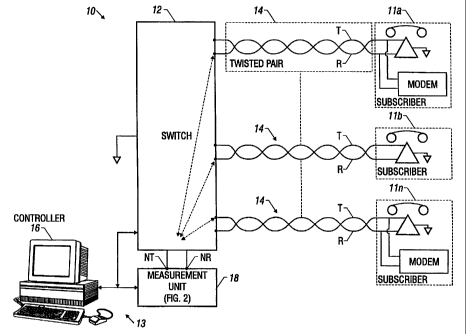
Referring now to FIG. 1, POTS telephone network 10 is shown. The
network 10 includes a plurality of subscribers 11 connected to a switch 12
(which is,
or is connected to, the central office) through transmission lines 14, which
in many
instances will be a twisted pair. A centralized test system controller (TSC)
16 is
connected to one, or more, measurement units 18, and is adapted to determined
whether the twisted pair transmission lines 14 are qualified for data signal
transmission. The measurement units 18 are connected to the switch 12, as
shown.
The test control system controller 16, measurement unit 18, and switch 12 are
3 0 interconnected as described in U.S. Patent No. 5,699,402 assigned to the
same
- 8 -
SUBSTITUTE SHEET (RULE 26)
CA 02350566 2001-05-02
WO 00/27134 PCT/US99/24832
assignee as the present invention, the entire subject matter thereof being
incorporated
herein. The measurement unit 18 will be described in detail hereinafter.
Suffice it to
say here that the unit 18 is adapted to test the twisted pair either on
demand, or
automatically, from a preprogrammed list of lines. It is noted that a
subscriber's
transmission loop can be tested from the central office because each
measurement unit
18 has access to every subscriber through the switch 12 and the techniques
employed
herein use test signals that pass through switch 12 without undue distortion.
The unit
18 gains access to test a subscribers loop through a switched test bus located
in the
switching element 12. The switched test bus disconnects the line to be tested
from the
switch 12, and connects it to the measurement unit 18.
More particularly, a system 13 is provided for automatically determining
qualification of the plurality of twisted pair transmission lines 11. The
system 13
includes the controller 16 and the measurement unit 18 which are coupled to
the
switch 12. The switch 12 is also coupled to the terminating ends of the
plurality of
twisted pair transmission lines 14. The controller 16, here a computerized
work
station, such as is commercially available from SUN Computers, Inc., is
provided for
feeding signals to the switch 12 and to the measurement unit 18. The
measurement
unit 18 will be described in detail in connection with FIG. 2. Suffice it to
say here that
the measurement unit 18 is coupled to the switch 12 and the controller 16 and
that
such unit 12 is adapted to feed test signals from the measurement unit 12 to a
selected
one of the twisted pair transmission lines 14 through the switch 12. The one
of the
twisted pair transmission lines 14 selected is in accordance with a control
signal fed to
the switch 12 by the controller 16. Further, measurement unit 18 isolates
resistance
imbalance between the pair of wires, T and R, in the selected one of the
twisted pair
transmission lines 14 in response to the test signals fed to such selected one
of the
twisted pair transmission lines 14, in a manner to be described. The
controller 16, in
response to the isolated resistance imbalance, is adapted to determine the
qualification
of the selected one of the twisted pair transmission lines 14 for data signal
transmission.
To qualify a subscriber loop for data transmission, the centralized test
- 9 -
SUBSTITUTE SHEET (RULE 26)
CA 02350566 2001-05-02
WO 00/27134 PCT/US99/24832
system controller 16 gathers information from many sources, one of which is
the
measurement unit 18. The test system controller 16 applies this information
using the
appropriate hardware and software to a set of rules described below which
determine
whether a tested line is capable of carrying data transmission signals (i.e,
the line is
qualified). The following steps are directed by software programmed in
controller 16
using known programming techniques.
One method for making a determination about the suitability of a
subscriber loop for data transmission, particularly either ISDN or ADSL type
data
transmission, is the Disqualification method. The Disqualification method
allows a
telephone company to test its transmission lines to determine which lines may
support
data transmission, and to disqualify those lines which do not. Under the
Disqualification method, the test system controller 16 gathers several factors
about the
test line including: (1) using any known technique to determine the length of
the line;
(2) using any known technique to determine the magnitude of any DC metallic
faults
present on the line; (3) using any known technique to determine the capacitive
balance
of the line; (4) using any known technique to detect the presence of load
coils on the
line, such as the one described in U.S. patent application 08/929,842 by Yun
Zhang
entitled "Fast and Noise-Insensitive Load Status Detection" which is hereby
incorporated by reference; (5) using any known technique to determine the
composite
noise on the line; and (6) using the technique described below to determine
the
resistive balance on the line. However, it will be appreciated that a line
might be
disqualified by using less than all of these techniques or by using additional
checks.
Referring now to FIG. 4, the test system controller 16 then executes the
following rules, using the appropriate hardware and software, to determine
whether a
2 5 line should be disqualified for data transmissions. A line is disqualified
if the test
system controller determines:
- That the line length is greater than some threshold, preferably in
the range of 4 to 6 kilometers, and more preferably 5.5 kilometers
(step 401); or
- That metallic faults are less than some threshold, preferably in the
- 10 -
SUBSTITUTE SHEET (RULE 26)
CA 02350566 2001-05-02
WO 00/27134 PCT/US99124832
range of 80 to 200 kilo-ohms, and more preferably 100 kilo-ohms
(step 402); or That capacitive imbalance is greater than some
threshold, preferably in the range of 0 to 5% and more preferably
greater than 0% (step 403); or
- That load coils are detected (step 404); or
- That noise is greater than some threshold, which is preferably
empirically determined (step 406); or
- That resistive imbalance is greater than some threshold, preferably
in the range of 0 to 50% or that the series resistive imbalance is
unstable, meaning that the measured series resistance imbalance
changes more than some threshold since a reference measurement
was made.
It will be appreciated that not all of these measurements might need to be
made to disqualify a line. Further, it should be appreciated that the
thresholds used for
each test might be different, depending on the type of data service. For
example,
ISDN data service can operate at a lower error rate than V.90 at a given level
of
instability in the series resistive imbalance. It is contemplated that the
thresholds will
be empirically determined, taking into account such factors as actual
experience and
the acceptable bit error rate specified by the user or other factors.
Another method for qualifying a subscriber loop for data transmission is
the Pre-Qualification method. The Pre-Qualification method allows a telephone
company to test its subscriber loops to determine which ones are capable of
supporting ISDN and ADSL type data services. Under the PreQualification
method,
the test system controller 16 makes the same measurements as described above
for the
Disqualification method.
FIG. 5 illustrates the method by which a subscriber line can be pre-
qualified for data services. Note that the system of FIG. 1 can, by
appropriate
programming and.commands input into controller 16 test all or some subset of
the
lines attached to switch 12. Very simply, if a line is not disqualified using
the tests
3 0 described above in conjunction with FIG.4, it can be concluded with a high
degree of
- 11 -
SUBSTITUTE SHEET (RULE 26)
CA 02350566 2001-05-02
WO 00/27134 PCTIUS99/24832
confidence that the line is qualified for data services. Notably, all of the
measurements needed to qualify the line can be made from one end of the line
and can
also be made through a switch.
A third method for qualifying a line for data transmission is the V.90
Disqualification method. The V.90 Disqualification approach enables a central
test
system controller 16 to test a transmission line to determine whether it may
handle a
V.90 analog modem.
As shown in FIG. 6, a line will be disqualified for V.90 data transmission
if test system controller 16, using the appropriate hardware and software,
determines:
using any known technique that the line circuit type equals Pair Gain (Step
601); or
using any known technique that the line circuit type equals universal DLC
(Step 602);
or using any known technique that the trunk to RAS path equals analog (Step
603); or
using the technique described below that the resistive imbalance is greater
than some
threshold (step 604), which in a preferred embodiment is about 1,000 ohms or
that the
imbalance is unstable, meaning that the measured imbalance changes more than
some
threshold amount. In a preferred embodiment, that threshold is 5%. However, it
is
contemplated that as the magnitude of the imbalance increases, a lower
percentage for
instability will be tolerated. Thus, the threshold for stability measurements
might be a
function of the magnitude of the imbalance. If a line is disqualified for V.90
mode,
the modem using that line operates at its slower fall back speed which is
commonly
called V.34. Again, the operator may not need to check for all of these
conditions in
every case since again subsets are permissible in some situations.
It is noted that each of these methods (i.e., Disqualification, Pre-
Qualification, and V.90 Disqualification) include a measurement of resistance
imbalance between the wires in the transmission line. In particular, the
stability of the
resistive imbalance is very important in qualifying a transmission line for
data signals.
The lack of stability is particularly harmful for signals in which information
is
encoded in the phase of the signal. It is also harmful because a shifting
imbalance can
cause adjacent pulses to smear together. One way to measure the stability of
an
3 0 imbalance is to take multiple measurements over an interval that would be
on the
- 12 -
SUBSTITUTE SHEET (RULE 26)
CA 02350566 2001-05-02
WO 00/27134 PCT/US99/24832
order of a second. Changes in imbalance could then be detected from changes in
the
measurement over that window. A second and potentially faster way to measure
the
stability of an imbalance is to make a plot of phase of the test line versus
frequency. if
the resistive imbalance is unstable, the curve will not be smooth (smooth is
not used
here in the mathematical sense), rather there will be many ripples and
possibly
discontinuities on the curve. The instable resistance could then be detected
though an
automatic technique to recognize a curve with these characteristics.
Referring now to FIG. 2, the measurement unit 18 measures resistive
imbalance in each of the wires, R and T of a twisted pair 14. This measurement
unit
18 may be used to determine whether the twisted pair 14 qualify for data
transmission
when such unit 18 is connected to a subscriber's transmission loop, as
described
above. Here, the measurement unit 18 contains a signal source 30, here a
voltage
source which is adapted to have its frequency swept in response to a signal
fed thereto
by the controller 16. Also included in the measurement unit 18 are a pair of
balanced
(i.e., having equal resistances) resistors RI and R2, and a pair of voltmeters
22 and 24.
The voltage source applies a common mode voltage to the pair of wires T, R of
the
twisted pair transmission line. More particularly, the voltage source has one
terminal
reference to ground potential and the other terminal connected in common to
the pair
of wires, T, R, here through the resistors R1 and R2, respectively, as
indicated.
Voltmeters 22 and 24, are provided to measure both the magnitude and the phase
of
the voltage at the node NT of tip wire T and the node NR of ring wire R,
respectively.
Alternately, measurement unit 18 in FIG. 2 is represented in FIG. 3 as
measurement unit 18'. Here, measurement unit 18'contains a signal source 30'
which
consist of a digital voltage frequency controller 31 coupled to a digital-to-
analog
converter 32, both connected to a clock 33. The signal source 30' is designed
to have
it frequency swept in response to a signal fed thereto by the controller 16.
Also
included in the measurement unit 18' is a pair of balanced resisters RI and
R2, and a
pair of analog-to-digital converters 22' and 24, also connected to clock 33.
Analog-
3 0 to-digital converters 22' and 23', measure both the magnitude and phase of
the voltage
- 13 -
SUBSTITUTE SHEET (RULE 26)
CA 02350566 2001-05-02
WO 00/27134 PCT/US99/24832
at node NT of tip wire T and the node RT of ring wire. R, respectively.
The equivalent circuit for an exemplary one of the twisted pair
transmission lines 14 is shown in FIG. 2. It is noted that the ring wire R and
the tip
wire T include series resistances RR and RT, respectively and shunt
capacitances CR,
CT, respectively. There is also a capacitance CTR between the tip and ring
wires, T
and R, respectively, as shown. It is noted that a resistance imbalance pR
between the
tip wire T and the ring wire R is represented here as shown in ring wire R. To
detect
and isolate resistive imbalance on a test twisted pair transmission line 14,
the
following steps are performed under the control of the test system controller
16:
(1) Signal source 30 applies a swept frequency excitation
voltage common mode with respect to ground through balance
resisters R1 and R2 to each wire R and T which make up the
transmission line 14. This signal typically ranges from 0 to 10
volts peak, and is swept in frequency, f, under the control of the
controller 16, from 0 to 20 kilohertz.
(2) Voltmeters 22 and 24 measure the resulting magnitude and
phase of each signal at nodes T and R with respect to ground.
These voltages, as a function of frequency, f, are called Va(f)
and Vb(f). The phase imbalance is equal to the difference in
phase between: (1) the phase of a signal produced in one of the
wires in the twisted pair transmission line with respect to the
applied voltage; and, (2) the phase of a signal produced in the
other one of the wires in the twisted pair transmission line with
respect to the applied voltage.
(3) The phase of the voltage Va(f) is then compared with the
phase of the voltage Vb(f) as a function of frequency to
determine the phase imbalance between the wires T and R (i.e.,
the difference in phase, 0o, between the phase of Va(f), oa(f),
and the phase of Vb(f), oa(f), as functions of frequency, f,
leaves us the difference in phase, or in other words, the phase
- 14 -
SUBSTITUTE SHEET (RULE 26)
CA 02350566 2001-05-02
WO 00/27134 PCT/US99/24832
imbalance, which equals to AO(f) =Oa(f)-ob(f)). If a line 14 is
balanced, i.e. no resistive, inductive, or capacitive imbalances
exist, then the signals measured from wire R will equal the
signal measured from wire T in both magnitude, Va(f) and
Vb(f), and phase, oa(f) and ob(f), as functions of frequency. If
a line is unbalanced then the signals measured at T and R will
not equal in magnitude Va(f) and Vb(f), or phase, oa(f) and
ob(f), or both, as functions of frequency.
(4) If a phase imbalance exists (i.e., 0o ? 0), the controller 16
proceeds to measure the frequency at which the largest phase
imbalance occurs. This value is called the phase peak frequency
or Fpk.
Referring now to FIG. 7, to identify the type of imbalance on a test line,
should one exist, the controller 16 uses the appropriate hardware and software
to
complete the following analysis. The controller 16 first establishes two
reference
frequencies, Fl and F2 (Step 701). Fl and F2 are computed based upon the
length of
the selected paired transmission line, and aid in determining the type of
resistive
imbalance present. The lower reference frequency is called F1 and the upper
reference frequency is called F2. The frequency Fl is an empirically defined
frequency equal to about 0.4 times F2, i.e. F2 divided by 2.5. F2 is the
frequency at
which a phase peak, Fpk, should occur a balanced wire R or T of a test
transmission
line 14. For example, FIG. 8 shows the phase of Va(f) versus frequency, oa(f),
for a 6
kilo-foot length of 24 gauge balanced twisted pair transmission line 14. In
this
example, F2 is equal to 3.86 kilohertz, and Fl equals roughly 1.5 kilohertz.
For a given line 14 under test, F2 is determined by using one of the
following three methods: First, F2 may be measured when the line 14 is in a
known
good state and that measurement may be stored in a system footprint as
described in
the above referenced U.S. Patent No. 5,699,402; second, F2 may be computed
from
3 0 line cable records which identify line lengths and loop records; and
third, F2 may be
- 15 -
SUBSTITUTE SHEET (RULE 26)
CA 02350566 2001-05-02
WO 00/27134 PCT/US99/24832
computed from measuring the line length and measuring the loop resistance
using any
known technique.
Next, the controller 16 identifies the type of imbalance present in the
transmission line 14 by comparing the lines 14 measured Fpk, to its previously
established Fl, F2 frequencies (Step 702). If the imbalance is capacitive, as
would be
caused by a single leg disconnect, the imbalance can be identified as such by
the
controller 16 if it finds that Fpk occurs before Fl (Step 703). For example,
FIG. 9
shows the computed phase imbalance AO(f) between oa(f) and ob(f) for a
resistive
imbalance located 3 Kilo-feet from the measuring unit 18 on a 6 Kilo-foot
length of
24 gauge twisted paired transmission line, i.e. one leg disconnected,
superimposed on
the plot of F2 as described above. Here, the Fpk of the tested transmission
line
occurred before F1 indicating that the imbalance is capacitive and so is
identified as
such by the controller 16.
Next, if the imbalance is inductive, as would be caused by a miswired load
coil, then the controller 16 identifies it as such by determining whether
there are two
Fpks, one positive and one negative, or by determining, should there is only
one Fpk,
that Fpk occurs after F2, (Step 704). For example, FIG. 10 shows the computed
phase
difference, #(f), between cpa(f) and ob(f) for an inductive imbalance at 3
Kilo-feet on
a 6 Kilo-foot twisted pair transmission line superimposed on a plot of F2.
Here, the
Fpks of the tested transmission line occurred twice, at Fpkl and Fpk2,
indicating that
the imbalance is inductive and so is identified as such by the controller 16.
Furthermore, if the imbalance is resistive, as would be caused by unequal
series resistance, then the controller 16 identifies it as such by determining
whether
the Fpk occurs after Fl, but before F2 (Step 705). For example, FIG. 11 shows
the
computed phase difference #(f) between oa(f) and ob(f) for a series resistive
imbalance of 500 ohms located 3 Kilo-feet from the measuring unit superimposed
on
a plot of F2. Here, the Fpk occurs after F1 and before F2 indicating that the
imbalance is resistive and so is identified as such by the controller 16.
FIG. 12 shows all four conditions, the phase difference 0O(f) between ~a(f)
3 0 and ~b(f) for a capacitive imbalance, an inductive imbalance or a series
resistive
- 16 -
SUBSTITUTE SHEET (RULE 26)
CA 02350566 2001-05-02
WO 00/27134 PCT/US99/24832
imbalance on a twisted pair transmission line 14, as well as oa(f) or ob(f)
for a
balanced twisted pair transmission line 14 superimposed on the same graph.
Moreover, the controller 16 can determine when a very unstable (i.e., time
varying) series resistive imbalance is present in a twisted pair transmission
line by
noting that the phase to frequency measurement for line are also unstable
(Step 706).
Such an unstable situation is seldom true for any other imbalance condition.
After determining the type of imbalance on a test line, the controller 16
may also provide a means to discover the location of the imbalance on a
twisted pair
transmission line 14. There exists many possible techniques for locating an
imbalance
on a test line. Below are the two preferred techniques used by the controller
16 to
measure the distance to the imbalance from the measuring unit 18.
FIG. 13 provides a flow chart for a method used by the test system
controller 16 to discover the location of an imbalanced resistance in a
twisted pair
transmission line 14. This method is called the Measurement of Capacitance to
ground method. First, the capacitance to ground of each wire T and R of the
twisted
pair transmission line 14 is measured using any known technique (Step 1301).
Next,
an swept (alternating) common mode voltage is applied to the twisted pair
transmission line 14 and the resulting magnitude, Va(f), Vb(f), and phase,
oa(f), Ob(f),
of the voltage on wires R and T are measured by measurement unit 18 (Step
1302).
Then, these values are used to compute the admittance of the twisted pair
transmission
line 14 at those frequencies (Step 1303). Next, capacitance for that test line
14 can be
directly computed for these frequencies and admittances, (Step 1304). Then the
controller 16 compares the capacitance measurements taken in step 1301 with
the
capacitance measurements derived from the admittance measurements in step
1304,
(Step 1305). If there is no series resistive imbalances present on either of
the wires
then both of the capacitances measured at the lower frequency will be slightly
smaller
than those measured at the higher frequency. If, however, a series resistance
imbalance is present in transmission line 14, the capacitance measured at 8
kilohertz
will be significantly smaller than the capacitance measured at 25 hertz.
Finally, the
3 0 controller 16 approximates the distance to the imbalance by dividing the 8
kilohertz
- 17 -
SUBSTITUTE SHEET (RULE 26)
CA 02350566 2001-05-02
WO 00/27134 PCT/US99/24832
derived capacitance by the per-unit-length capacitance to ground for twisted
paired
transmission line 14 under test and comparing the value found to reference
data, (Step
1306).
FIG. 14 provides a flow chart for a second approach used by the test
system controller 16 to discover the location of an imbalance on a twisted
pair
transmission line 14 called the Phase Difference Peak approach. This approach
may
also be used to determine the magnitude of a series resistive imbalance.
First, the
controller 16 determines whether a series resistive imbalance is present by
comparing
Fpk to Fl and F2 as described previously in this patent application (Step
1401). Then,
if such an imbalance exists, the controller 16 applies an alternating common
mode
voltage signal through measurement unit 18 to wires T and R of the twisted
paired
transmission line 14, (Step 1402). Next, the controller 16 compares the
absolute
magnitude of the voltage signals, Va(f) and Vb(f), and Fpks for the two
signals for
wires T and R, to a list of reference magnitudes for a given line construction
(Step
1403). Then the controller 16 determines the location of the series resistive
imbalance
based on a comparison between the measured data and the reference data (Step
1404).
The controller 16 compares the frequency at which phase ~a(f) and ~b(f) occurs
to a
list of reference frequencies for a model of a twisted pair transmission line
14 of like
construction (Step 1405). Then the controller 16 estimates the magnitude of
the series
resistive imbalance based on a comparison between the measured data and the
list of
reference frequencies for a model twisted pair transmission line 14 of like
construction (Step 1406).
Other embodiments are within the spirit and scope of the appended claims.
For example, the invention is described in conjunction with a twisted pair
transmission line. The techniques might be applied to any transmission line
with at
least two legs.
Also, an important aspect of line qualification and line disqualification
using measurements taken from a single point is the ability to detect
imbalances,
particularly series resistance imbalances using single point measurements, and
3 0 particularly single point measurements that pass through a switch. Time
domain
- 18 -
SUBSTITUTE SHEET (RULE 26)
CA 02350566 2001-05-02
WO 00/27134 PCT/US99/24832
reflectometry (TDR) might also be used for such measurements. However, to make
TDR measurements through a switch, the pulse widths must be chosen carefully.
Appropriate pulse widths are described in the above mentioned patent
5,699,402.
Another way to determine imbalance on a transmission line is through the
use of data generated in a modem training sequence. When a data connection is
established between two modems over a transmission line, the modems undergo a
training sequence. In the course of training, the modems can compensate to
some
extent for series imbalances on the transmission line. Currently, the
information that
indicates the amount of compensation is not used for testing. However, if the
information on compensation needed for imbalance were saved for each line,
comparisons could be made to determine whether the compensation has changed
over
time. If the compensation changed, it would indicate an unstable imbalance.
While
such data might not be available to pre-qualify a line, it could be used to
disqualify a
line or to diagnose network faults.
Also, it should be noted that the disclosed embodiment illustrated detecting
resistive imbalance from a single point, which is the end of the line
connected to a
switch. It is not necessary that the test equipment be connected to the
network at this
point.
- 19 -
SUBSTITUTE SHEET (RULE 26)