Note: Descriptions are shown in the official language in which they were submitted.
CA 02350731 2004-06-11
MOLD CLAMPING APPARATUS.AND MOLD CLAMPING METHOD
BACKGROUND OF THE INVENTION
l.Field of the Invention
The.invention relates to a mold clamping apparatus and a
mold clamping method, and more particularly a mold clamping
apparatus for closing. and holding molds in, which mold
opening force is generated by providing inside thereof with
a pressure for opening the mold and a mold clamping method
using the same.
2.Description of the Related Art
For example, in hydraulic pressure bulging processing,
with both ends of a material pipe sealed, the material pipe
is formed to a predetermined shape by. expanding a diameter
thereof or the.like by raising the pressure of the liquid
.charged inside. Generally, the hydraulic pressure bulging
processing apparatus comprises high pressure liquid supply
device which supplies liquid such as water at a high
pressure to the inside of the material pipe, a mold~for
capturing the periphery of the material pipe and axially
pressing device which presses ends of the material pipe in
the axial direction. The mold in the hydraulic pressure
bulging processing apparatus is divided for accommodating
the material pipe inside and taking out a molded product
by the hydraulic pressure bulging processing. When carrying
out the hydraulic pressure bulging processing by expanding
the diameter of the material pipe or the like, a force
intending to open the mold (mold opening force) is generated
by the pressure of the liquid supplied to the inside of the
material pipe. Thus, the mold is provided with a mold
1
CA 02350731 2001-06-15
clamping apparatus in order to open/close the mold and hold the
mold (mold clamping) in a closed state resisting a pressure
applied forcing the mold to be opened during molding. As the mold
clamping apparatus, generally, a general-purpose hydraulic press
has been used. This general-purpose hydraulic press has a
sufficiently large capacity with a huge ram and bed so as to be
capable of coping with molds of various sizes. In such a general-
purpose hydraulic press, columns are erected to support a crown
receiving a pressure applied by the ram (for example, see Japanese
Patent Laid-Open Publication No. HEI 5-329693).
Products molded by hydraulic pressure bulging processing include
not only a straight product also but curved or bent products.
Thus, as shown in Fig. 37, the mold 2 is also formed in a curved
or bent shape. The hydraulic pressure bulging processing
apparatus may be provided with axially pressing device 22 which
presses ends of a material pipe in the axial direction, which is
provided on ends of the mold 2 such that it is inclined with
respect thereto as shown in Fig. 36.
The hydraulic pressure bulging processing may include a case of
forming a T-shaped branch pipe from a straight material. In this
case, the mold 2 is provided with a back pressure counter cylinder
26 for controlling a back pressure of the branch pipe to be formed,
as shown in Fig. 34. The mold 2 includes a portion 2a for
accommodating a straight material pipe W and a portion 2b for
forming the branch pipe. The axially pressing devices 22 are
provided on both end portions of the portion 2a for accommodating
the material pipe W. The back pressure counter cylinder 26 is
2
CA 02350731 2001-06-15
provided at an end of the portion 2b in which the branch pipe is
to be formed, such that it is protruded from the mold 2. When
forming the branch pipe, first, as shown in Fig. 34A, the material
pipe W is disposed in the mold 2 and then, both ends thereof are
sealed with the axially pressing devices 22. Liquid such as water
is supplied at a high pressure through ends of the material pipe W
into the inside thereof from high pressure liquid supply device
(not shown) through the axially pressing devices 22, and both ends
of the material pipe W are pressed with the axially pressing
devices 22. Consequently, as shown in Fig. 34B, the material pipe
W is expanded into the portion 2b in which the branch pipe is to
be formed. At this time, growth of the branch pipe is controlled
with a piston 26a of the back pressure counter cylinder 26
pressing an end of the branch pipe so that a top portion of the
expanded branch pipe is not ruptured, such that the piston 26a is
retreated synchronously with a supply of liquid into the material
pipe W by the high pressure liquid supply device and pressing on
both ends of the material pipe W by the axially pressing devices
22, as shown in Fig. 34C.
When drilling a hole in a molded product W', a hole punch 24
(see Fig. 1) is provided in the mold 22 and as shown in Fig. 38,
driving cylinders 25 for the hole punch 24 are provided so as to
be protruded from the mold 2. Further, a cylinder for driving an
ejector may be provided so as to be protruded from the mold 2 in
order to take out the molded product W' from an opened mold 2 (not
shown). Device each having a specified function necessary for
molding such as the back pressure counter cylinder 26, the driving
3
CA 02350731 2001-06-15
cylinder 25 for the hole punch 24 and a driving cylinder for the
ejector are referred to as functional devices.
As for a press frame, as disclosed in Japanese Utility Model No.
5-44396, and the like, a frame 101 having a holed section
constructed by laminating plural sheet-like frame materials 112
whose center portion is cut out has been well known (Fig. 39). A
central cut-out portion 115 in the press frame disclosed in
Japanese Utility Model No. 5-44396 contains a pressure applying
cylinder, a pressure receiving member and a mold although a
representation thereof is omitted in Fig. 39.
In the hydraulic pressure bulging processing apparatus of the
above-described related art, a general-purpose hydraulic press is
employed as a mold clamping apparatus. The hydraulic press is
provided with a huge ram and bed and further, the entire equipment
of the hydraulic press is of a huge construction because it
employs a robust structure for preventing distortion of the ram
and bed, and the equipment cost becomes accordingly high.
Consequently, a large area and height for installing such huge
equipment is necessary and further, not only a large amount of
operating energy is also necessary, but also there is a problem
that the hydraulic pump always has to be driven thereby inducing
an energy loss. Further, the hydraulic press takes a long time
for opening/closing the mold because the ram is huge. Still
further, because in the general-purpose hydraulic press used as a
mold clamping apparatus, columns for supporting the ram, crown and
the like are erected, it is difficult to secure a good working
efficiency in carrying the material pipe W into the mold and
4
CA 02350731 2001-06-15
taking out a molded product W'.
In the press frame having a closed section whose central portion
is cut out as disclosed in Japanese Utility Model NO. 5-44396, for
example, its central cutout portion is provided with a pressure
applying cylinder and a pressure-receiving member. If this press
frame having the closed section is applied to the mold clamping
apparatus for the hydraulic pressure bulging processing or the
like, the central cut-out portion in the press frame needs to be
formed large enough for the pressure applying cylinder to be
capable of opening/closing the mold and therefore, the entire size
of the press frame becomes large, which is a problem to be solved.
In this case, hydraulic pressure driving device and pressure
application control device that drives the pressure applying
cylinder need to be provided separately from the high pressure
liquid supply device that supplies liquid such as water at a high
pressure to the inside of the material pipe. Thus, there is a
problem that equipment cost is increased and maintenance for the
hydraulic driving device is necessary, and it is necessary to
control the hydraulic driving device so as to drive the pressure
applying cylinder accurately as set up.
In case of the press frame formed to have this closed section,
if the central cut-out portion is not provided with any pressure
applying cylinder and instead, the mold 2 is held directly by the
frame 101 as shown in Fig. 35, the mold 2 can be inserted or taken
out only in the longitudinal direction with respect to the frame
101, because the frame 101 is formed with the closed section whose
central portion is cut out. Therefore, installation length L has
CA 02350731 2001-06-15
to be as long as a sum of the length of the frame 101 and the
length of the mold 2. Further, because the quantity of moving of
the mold 2 is increased, it is difficult to reduce the cycle time.
If the mold 2 held by the central cut-out portion 115 in the
frame 101 has the axially pressing devices 22 which is inclined
with respect to the mold, the central cut-out portion 115 in the
frame 101 has to be formed large enough for the axially pressing
devices 22 to be capable of passing through as shown in Fig. 36.
Therefore, the entire frame 101 needs to be formed sufficiently
large. In this case also, the mold needs to be formed with a
height T far larger than necessary for the mold 2 to be held by
the central cut-out portion 115 formed large (see a portion above
two-dot and dash line in Fig. 36)
If a product to be molded by the hydraulic pressure bulging
processing is a curved or bent product, the central cut-out
portion 115 having a width S allowing a maximum width of the
curved or bent mold 2 needs to be formed in the frame 101 as shown
in Fig. 37 and therefore, the entire frame 101 has to be formed
large.
In case where as shown in Fig. 38, the mold 2 is provided with
the functional device such as the back pressure counter cylinder
26, the driving cylinder 25 of the hole punch 24 and the ejector
also, the central cut-out portion 115 with a width S which allows
the functional device such as the back pressure counter cylinder
26, the driving cylinder 25 of the hole punch 24 and the ejector,
protruded from the mold 2 to pass through needs to be formed. As
a result, the entire frame 101 has to be formed large.
6
CA 02350731 2001-06-15
The frame 101 constructed by laminating sheet-like frame
materials 112 whose central portion is cut out as disclosed in
Japanese Utility Model No. 5-44396 has a closed section as shown
in Fig. 39. Therefore, it is difficult to insert a grinding
apparatus and carry out post processing for the central cutout
portion 115 to have a smooth surface when the frame materials 112
are laminated. Thus, there is a problem that the central cutout
portion 115 in each frame material 112 has to be positioned at a
high precision when laminating the frame materials to form a frame.
SUMMARY OF THE INVENTION
Accordingly, an object of the invention is to provide a mold
clamping apparatus capable of holding the mold securely resisting
a pressure intending to open the mold with a simple structure,
improving molding efficiency and achieving compactness of the
apparatus.
To achieve the above-described object, according to a first
aspect of the invention, there is provided a mold clamping
apparatus comprising: a mold in which a mold opening force is
generated by applying a pressure for opening the mold to the
inside of the mold; a frame including a holding portion for
holding the mold resisting the generated mold opening force and an
open portion allowing the mold to be inserted into/taken out from
the holding portion in a direction of the shorter side of the
mold; mold moving device that moves the mold to insert/take out
the mold into/from the holding portion through the open portion in
the frame; and mold opening/closing device that opens/closes the
7
CA 02350731 2004-06-11
mold located outside the frame.
Because the mold of the invention is moved in the direction of
the shorter side thereof with the mold moving device, it is
inserted--through the open-portion-in the-frame and held by the
holding portion. Further, it is taken out of the frame through the
open portion. As a result, the quantity of moving the mold for
inserting or taking out the mold into/from the frame is small, so
that this is carried out in a short time. As a result; cycle time
is reduced and molding efficiency is improved. Although upon
molding, a mold opening force is generated when a pressure is
applied to the inside of the mold, the mold is held securely in a
closed.state resisting the mold opening force generated upon
molding. When the mold is taken out of the frame from the holding
portion through the open. portion, the mold is opened/closed with
the mold opening/closing device. Because the mold is opened or
closed outside the frame, a material or a molded product can be
inserted/taken out into/from the mold securely and easily.
According to a preferred embodiment of the invention, the frame
comprises an overhang portion and a base portion, composing the
holding portion and a post portion for joining, the overhang
portion to the base portion, and
molding parameters of respective portions of the frame are set up
so that a stress index value K calculated according to the
following expression i-s in a range of 0.2 to 15:
K = { (6~E/Da) + (~/D) ~~1 + (0.0188D/C + 0.243) (D/R)1-la~
wherein is a maximum width of the overhang portion; D is a
maximum width of the post portion; E is a minimum distance from
8
CA 02350731 2001-06-15
the post portion to the center in the mold to which a pressure is
applied; R is a maximum curvature radius of a connecting corner
portion between the overhang portion or base portion and the post
portion; and ~ is a width of a projection plane perpendicular to a
direction of a mold opening force as a portion to which a pressure
in the mold is applied.
By setting up molding parameters of the respective portions of
the frame according to the above-described equation, the holding
portion in the frame is provided with a pressure so as to hold the
mold in which the mold opening force is generated, securely in a
stable condition. In case where the mold is used for carrying out
hydraulic pressure bulging processing on a material pipe, as for
the molding parameters for the frame, E is a minimum distance from
the post portion up to the center of the material pipe in the mold
and ~ is a width of a projection plane perpendicular to a
direction of a mold opening force inside a product formed from the
material pipe.
Further, the mold clamping apparatus may further comprise mold
closing force application device that applies a force intending to
close the mold resisting the mold opening force of the mold.
Although the frame may be elastically deformed so as to be
extended slightly depending on a pressure applied to the inside of
the mold causing the mold to be opened, the mold closing force
application device applies a force for closing the mold resisting
the mold opening force and therefore, the mold is prevented from
being opened. Consequently, it is possible to form a high
precision product reliably.
9
CA 02350731 2001-06-15
Further, according to another embodiment of the invention, a
mold clamping apparatus comprises: a mold in which a mold opening
force is generated by applying a pressure for opening the mold; a
frame having a holding portion for holding the mold resisting the
generated mold opening force; and mold closing force application
device, provided in the holding portion of the frame, that applies
a force higher than the mold opening force in a direction of
closing the mold using a pressure applied to the inside of the
mold.
According to this embodiment, although the mold opening force is
generated in the mold when pressure is applied to the inside
thereof at the time of molding, the mold is held in a closed state
resisting the mold opening force because it is held by the holding
portion in the frame. Then, because the mold closing force
application device applies a force higher than the mold opening
force in the direction intending to close the mold resisting the
mold opening force generated by the mold closing force application
device, a slight mold opening accompanied by a slight extension
due to deformation of the frame is prevented. The mold closing
force application device has a simple structure and is easy to
control since it uses the pressure applied intending to open the
mold for applying this pressure to the mold.
The frame of the above-described embodiment may be constructed
by laminating a plurality of sheet-like frames in the longitudinal
direction of the frame.
Each frame material is capable of holding the mold resisting a
stress applied to the frame material when a pressure applied
CA 02350731 2001-06-15
intending to open the mold is applied. Because each frame
material is sheet-like, the open portion and the holding portion
are formed easily in each predetermined shape. By adjusting the
number of the frame materials, a frame of a desired shape is
constructed at a low cost depending on the mold.
Further, the frame materials composing the frame may be so
constructed that the strength of the surface is higher than the
strength of the central portion in the thickness direction and
that the stress concentration portion is chamfered. Further,
although decarburized layer still exists on the surface of the
frame material, it is possible to remove the decarburized layer on
the surface of the frame material in the stress concentration
portion by chamfering the stress concentration portion.
Consequently, the strength of the entire frame can be enhanced
and reduction of the size and cost can be achieved. Further,
reduction of processing cost and improvement of yield rate for
steel plate can be achieved.
Further, the frame may be constructed by laminating frame
materials each having different strength level and thickness.
Consequently, material having a high strength level is utilized
in a maximum stress portion of the frame and inexpensive material
having a low strength level is used in a portion in which a low
stress is generated. Therefore, there is no waste in material
selection, so that production cost can be suppressed.
According to still another embodiment of the invention, there is
provided a mold clamping method comprising: preparing a mold in
which a mold opening force is generated by applying a pressure for
11
CA 02350731 2001-06-15
opening the mold to the inside of the mold, a frame containing a
holding portion for holding the mold resisting the generated mold
opening force and an open portion which allows the mold to be
inserted into/taken out from the holding portion in a direction of
the longer side of the mold; and inserting the mold into the
holding portion through the open portion in the frame by moving
the mold in a direction of the shorter side of the mold and
closing and holding the mold, and after molding, taking out the
mold from the holding portion through the open portion and
opening/closing the mold outside the frame.
According to this embodiment, by moving the mold in the
direction of the shorter side of the mold, the mold is inserted
into the holding portion through the open portion in the frame and
held in a condition that it is closed. After the molding, it is
taken out from the holding portion through the open portion and
then, the mold is opened or closed outside the frame. Such a
simple structure achieves reduction of cycle time used for
carrying the material into the mold and taking out a molded
product, thereby improving working efficiency and molding
effectiveness.
BRIEF DESCRIPTION OF THE DRAWINGS
Fig. 1 is a front view showing an embodiment of a mold clamping
apparatus of the invention;
Fig. 2 is a side view of Fig. 1;
Fig. 3 is a plan view of Fig. 1;
Fig. 4 is a sectional view for explaining a frame of the mold
12
CA 02350731 2001-06-15
clamping apparatus of the invention and an initial state for
carrying out hydraulic pressure bulging processing of a mold;
Fig. 5 is a sectional view for explaining a state in which the
mold is closed from the state shown in Fig. 4;
Fig. 6 is a sectional view for explaining a state in which the
mold is inserted into a holding portion through an open portion
from the state shown in Fig. 5 such that it is held thereby;
Fig. 7 is a sectional view for explaining a state in which
liquid is supplied to the inside of a material pipe at a high
pressure so that a molded product is finished;
Fig. 8 is a schematic diagram for explaining the shape of a
frame to be set;
Fig. 9 is an explanatory diagram showing another embodiment
provided with plural holding portions and open portions;
Fig. l0A is a graph showing a volume ratio to a hydraulic press,
of a frame formed under formation parameters set up based on a
stress index value calculated according to the invention;
Fig. lOB is a graph showing changes to the stress index value,
of a strength allowance of a frame formed under formation
parameters set up based on a stress index value calculated
according to the invention;
Fig. 11 is a sectional view of a frame plate in a stress
concentration portion;
Fig. 12 is a graph showing a stress distribution;
Fig. 13 is a front view of a frame material applied for a
hydraulic molding apparatus;
Fig. 14 is a graph showing a strength distribution of the frame
13
CA 02350731 2001-06-15
material;
Fig. 15 is a front view of a frame material according to another
embodiment;
Fig. 16 is a sectional view (taken along the line XVI-XVI in Fig.
15) of a frame material in the stress concentration portion;
Fig. 17 is a perspective view showing an apparatus frame,
material and the like according to an embodiment of the invention;
Fig. 18 is a graph showing a relation between a stress at a
stress calculation point in each steel plate and fatigue limit of
the steel plate used;
Fig. 19 is a perspective view showing an apparatus frame and
mold according to still another embodiment;
Fig. 20 is a graph showing a relation between a maximum stress
in each frame plate and fatigue limit in the frame plate used;
Fig. 21 is a perspective view for explaining a state in which
the mold is held in the mold clamping apparatus of the invention;
Fig. 22 is a perspective view showing a case where axially
pressing device incliningly provided on a mold held by the mold
clamping apparatus of the invention is provided;
Fig. 23 is a perspective view showing a case where the mold to
be held by the mold clamping apparatus of the invention is
provided with back pressure counters and driving portion for a
hole punch such that they are protruded from the mold;
Fig. 24 is a perspective view showing still another embodiment
of the frame of the invention;
Fig. 25 is a perspective view showing a state in which the frame
materials are disposed and laminated depending on the shape of the
14
CA 02350731 2001-06-15
mold when the mold to be held by the mold clamping apparatus of
the invention is formed so as to be curved or bent;
Fig. 26 is a plan view showing still another embodiment of the
frame material composing the frames of the invention;
Fig. 27 is a perspective view showing still another embodiment
having a structure for surrounding the peripheries of the mold
using sheet-like frame materials at both ends of the frame;
Fig. 28 is a view corresponding to a section taken along the
line IIXVIII-IIXVIII of Fig. 1 for explaining an embodiment in
which mold closing force application device of the invention is
applied;
Fig. 29 is a schematic diagram showing the structure of the mold
closing force application device of the invention;
Fig. 30 is a schematic diagram for explaining a state in which a
pressure for canceling the mold opening force in the mold is
applied by simultaneously supplying liquid into the inside of a
material pipe and a cylinder of the mold closing force application
device from high pressure liquid supply device;
Fig. 31 is a schematic diagram showing a structure of another
embodiment of the mold closing force application device of the
invention;
Fig. 32 is an explanatory view showing setting of a pressure
receiving area in the cylinder of the mold closing force
application device;
Fig. 33 is a perspective view showing an embodiment in which a
frame is comprised of a frame material containing a single holding
portion and open portion and a frame material containing plural
CA 02350731 2001-06-15
holding portions and open portions, and a mold starting device is
used for both the molds and can be inserted into/taken out from
the holding portion in the frame;
Fig. 34 is an explanatory view showing an operation of a back
pressure counter provided for controlling the back pressure in a
branch pipe to be formed by hydraulic pressure bulging processing;
Fig. 35 is a perspective view showing a case where the mold is
held in a conventional frame by comparing with the frame of the
invention;
Fig. 36 is a perspective view showing a case where the mold is
held in the conventional frame while axially pressing device is
provided on the mold such that it is inclined for comparison with
the frame of the invention;
Fig. 37 is a perspective view showing a case where a mold formed
in a curved or bent state is held in the conventional frame for
comparison with the frame of the invention sown in Fig. 25;
Fig. 38 is a perspective view showing a case where a mold
provided with a back pressure counter or a hole punch is held in
the conventional frame for comparison with the frame of the
invention shown in Fig. 23; and
Fig. 39 is a perspective view for explaining a frame having a
closed section constructed by laminating sheet-like frame whose
central portion is cut out.
DETAILED DESCRIPTION OF THE PREFERRED EMBODIMENTS
Hereinafter, a case where an embodiment of the invention is
applied to a hydraulic pressure bulging processing apparatus for
16
CA 02350731 2001-06-15
forming a material pipe to a predetermined configuration will be
described in detail with reference to Figs. 1 to 27.
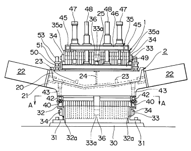
The mold clamping apparatus of the invention has a frame 1 for
holding a mold 2 in which a mold opening force is generated when a
pressure for opening the mold is applied. The frame 1 comprises a
holding portion 10 for holding the mold 2 resisting a mold opening
force generated when a pressure for opening the mold is applied
inside, and an open portion 11 allowing engagement or discharge of
the mold 2 with respect to the holding portion 10 in a direction
of the shorter side of the mold. Further, the mold clamping
apparatus of the invention comprises mold moving device 3 for
inserting or taking out the mold 2 into/from the holding portion
in the direction of the shorter side of the mold via the open
portion 11 of the frame 1 and a mold opening/closing device 4 for
opening/closing the mold 2 located outside the frame 1.
As shown in Figs. 4 to 7, the mold 2 is used for carrying out
hydraulic pressure bulging processing on a material pipe W and
comprises an upper mold 20 and a lower mold 21. They have
accommodating portions 20a, 21a respectively for capturing the
material pipe W and forming it to a predetermined shape, the
accommodating portions being provided in abutting faces
therebetween. The accommodating portions 20a, 21a in the mold 2
of this embodiment are formed so as to form a molded product W'
having a rectangular section from the material pipe W having a
circular section. Axially pressing device 22 is provided on each
end of the mold 2. An end of each axially pressing device 22 is
inserted into end portions of each of the accommodating portions
17
CA 02350731 2001-06-15
20a, 21a so as to press end portions of the material pipe
accommodated in the accommodating portions 20a, 21a. Both ends of
the material pipe W are sealed. Thus, high pressure water can be
supplied from high pressure liquid supply device 5 into inside of
the material pipe W and air in the material pipe W can be
discharged. The high pressure liquid supply device 5 shown in Fig.
30 is connected to the axially pressing device 22 of Fig. 22. The
high pressure liquid supply device 5 supplies liquid such as
pressurized water to inside of the material pipe W which is
accommodated in the accommodating portions 20a, 21a with both ends
thereof sealed, through the axially pressing device 22.
The mold 2 of this embodiment further comprises a molded product
pushing cylinder (ejector unit) 23 for taking out a molded product
W' having a rectangular section from the accommodating portion 20a,
a hole punch 24 and a driving cylinder 25 (piercing unit), as
function device as shown in Fig. 1. The driving cylinder 25 of
the hole punch 24 is provided such that it is protruded from the
mold 2.
On the other hand, according to the embodiment shown in Figs. 4
to 7, the frame 1 is formed so as to have a C-shaped section which
is cut out from one face up to its center. Here, as shown in Fig.
8, a vertical portion of the frame 1 is called post portion la, an
upper horizontal portion connected to this post portion la is
called overhang portion lb while a lower horizontal portion
connected to the post portion la is called base portion lc. The
overhang portion lb and the base portion lc are formed
substantially parallel to each other in terms of their opposing
18
CA 02350731 2001-06-15
faces, so that a holding portion 10 of the frame 1 is constructed
with such parallel opposing faces. The open portion 11 of the
frame 1 is constructed between ends of the overhand portion lb and
base portion lc.
The frame 1 of this embodiment is formed by laminating a
plurality of frame materials 12. Each frame material 12 is formed
in the shape of a plate such that the holding portion 10 and the
open portion 11 are made as in the above described embodiment.
Each frame material 12 is composed of a rectangular rolled sheet
material and by cutting out from one side edge toward the center,
the holding portion 10 and the open portion 11 can be formed
easily at low cost. Further, because in the frame 1 of the
invention, each frame material 12 has the open portion 11 unlike a
frame 101 having a closed section as indicated by a related art of
Fig. 39, a grinding processing unit can be brought to the holding
portion 10 easily. Accordingly, post processing for finishing the
surface of the holding portion 10 and the open portion 11 smooth
after laminating the frame materials 12 is facilitated. Therefore,
it is not necessary to position and laminate the frame materials
12 at high precision such that the holding portion 10 and the open
portion 11 have a continuous smooth surface. In the meanwhile,
the frame 1 of the invention is not restricted to this structure
formed by laminating a plurality of plate frame materials, but may
be formed in the form of an integrally molded block.
As shown in Fig. 5, an interval T1 of the holding portion 10 is
set up a little wider than the height T2 of the mold 2 so that the
mold 2 in which a mold opening force is generated can be held
19
CA 02350731 2001-06-15
securely and engaged by insertion. Meanwhile, the invention is
not restricted to this embodiment, but may have an H-shaped
section in which the holding portion 10 and the open portion 11
are formed on each of two faces opposing each other of the frame 1.
Although not shown, the invention may be formed so as to have an
E-shaped section in which plural open portions 11 and holding
portions 10 continuous thereto are arranged on a side face.
Next, setting of molding parameters for the frame of the
invention will be described.
As shown in Figs. 8 and 9, as the molding parameter for the
frame, assuming that a maximum width of the overhand portion lb is
C(m), a maximum width of the post portion la is D(m), a minimum
distance from inside of the post portion la to the center of the
material pipe W in which high pressure fluid is supplied
internally is E(m), a maximum curvature radius of part between the
post portion la and the overhand portion lb or the base portion lc
is R(m), a maximum width of a projection plane perpendicular to a
direction of a mold opening force generated in the mold 2 inside
the product W' as a portion to which a pressure in the mold is
applied is ~(m), and a maximum arrival pressure to be applied to
inside of the material pipe is P(Pa), experiments were carried out
with frames of various shapes. Consequently, the inventor found
that a stress index value K which was a ratio between the maximum
arrival pressure P and the maximum stress O'(Pa) to be applied to
the frame could be obtained by the following equation.
K = U/P = {(6~E/D2) + (~/D)}(1 + (0.0188D/C + 0.243)(D/R)lme)]
With respect to an estimated value of the stress index value K
CA 02350731 2001-06-15
obtained from this equation, contribution of an observed value
obtained through experiment is 0.965. If the overhand portion lb,
the base portion lc and the post portion la are formed along
straight line without forming the connecting corner portion with
curvature, 0 is substituted for the D/R in the above equation.
Fig. l0A is a graph showing a relation between the calculated
stress index value K and a ratio between a volume of a frame
formed with molding parameter set up by the invention and the
volume of a general-purpose hydraulic press explained in related
art. If the molding parameter is set up so as to increase the
stress index value K, the volume of the frame 1 can be reduced.
As evident from this graph, if the calculated stress index value K
is substantially more than 0.2, the volume of the frame 1 of the
invention can be reduced as compared to the volume of the general-
purpose hydraulic press.
Fig. lOB is a graph showing a relation between the calculated
stress index value K and an allowance (safety rate) of the
strength of the frame formed with the molding parameter set up by
the invention. If the molding parameter is set up so as to
increase the stress index value K, the excess rate of the strength
of the frame 1 is decreased. As evident from this graph, if the
calculated stress index value K was substantially less than 15, it
was found that there is no problem in the strength of the frame 1
of the invention.
Thus, according to the invention, the maximum width C of the
overhang portion lb, the maximum width D of the post portion la,
the minimum distance E from inside of the post portion la up to
21
CA 02350731 2001-06-15
the center of the material pipe W, and the maximum curvature
radius R of the connecting corner portion between the post portion
la and the overhang portion lb or the base portion lc as the
molding parameter of each portion of the frame so that the stress
index value K calculated from the above equation is in a range
from 0.2 to 15. Consequently, the frame 1 can obtain an optimum
frame configuration which achieves compactness in its volume,
avoids plastic deformation by a mold opening force of the mold 2,
ensures a strength capable of holding the mold 2 in a stable
condition and endures a fatigue to a repeated load by the mold
opening force of the mold 2 in continuous molding cycle.
If the mold opening force is generated, a reaction force is
applied to the frame 1 upward in a single axis direction, so that
a bent portion of the frame 1 becomes a stress concentration
portion 5. According to the conventional related art, material
ensuring a strength capable of preventing a damage of this stress
concentration portion is selected and the entire frame is formed
of that material.
According to this embodiment, as the frame material 12, a frame
material 12 in which the strength of its surface is higher than
the strength of the central portion thereof is used. Such a frame
material 12 can be manufactured easily by hardening the surface
layer by quenching the surface and conditioning the composition
thereof. Although for example, in an ordinary frame material 12
having a strength 590 MPa, the surface and the central portion of
the frame 12 have entirely uniform strength of 590 MPa, the
central portion of the frame material 12 can be 540 MPa while that
22
CA 02350731 2001-06-15
of the surface thereof can be 640 MPa by quenching and tempering
the surface.
A stress concentration portion 14 in the frame material 12 is
chamfered as shown in Fig. 11. Because a single axis stress is
generated in the frame 1 as described above, if the chamfering is
not carried out, a uniform stress is generated on the entire frame,
so that the central portion of the frame material 12 is required
to have a strength capable of bearing that stress. If the
chamfering processing is carried out, stress distribution is
intensified in the chamfered portion more than the central portion
of the frame material 12, so that stress bearing of the central
portion of the frame material 12 is reduced correspondingly.
Thus, by limiting a portion in which maximum stress occurs in
the stress concentration portion 14 to the surface portion of each
of the laminated frame materials 12 and adjusting the strength of
the surface portion of each frame material 12 so as to be capable
of bearing this stress, fatigue strength of an entire frame can be
ensured. That is, as compared to a case of manufacturing the
entire frame of uniform material capable of bearing maximum stress
of the stress concentration portion, evidently, production cost
thereof is lower and further the frame 1 can be reduced in size by
an amount corresponding to improvement of the surface strength,
thereby leading to reduction of production cost as well.
For example, in case of constructing the frame 1 shown in Fig.
13 by laminating the frame materials 12 each having a thickness of
50 mm, if a conventional uniform frame material 12 having a
strength of 590 MPa is employed, the frame material needs to be
23
CA 02350731 2001-06-15
1500 mm in height, 1,000 mm in depth and 1500 mm in width and the
weight thereof is 13.6 tons. If the strength of the surface
portion is raised to 640 MPa as shown in Fig. 5 by quenching the
surface of the frame material 12 having the strength of 540 MPa in
the central portion thereof and only the stress concentration
portion 5 of the frame material 12 is chamfered by 1 mm each from
both sides, the frame can be formed 1360 mm in height, 960 mm in
depth and 1500 mm in width, so that the weight thereof can be
reduced to 11.3 tons.
Thus, the size of the frame under the same service condition can
be reduced and the frame 12 itself to be used may be of an
inexpensive material having a low strength level. Therefore,
production cost can be greatly reduced.
As shown in the figure as an embodiment of another frame
material, a frame material 12 in which decarburized layer
(ordinarily, about 0.2 to 0.5 mm) remains is employed. That is,
each frame material 12 is a frame material 12 just rolled with
scale remaining or a frame material 12 from which the scale in the
surface layer is removed by blasting or the like. A material from
which the decarburized layer is not removed by cutting or grinding
is used. Such a frame material 12 is inexpensive and because
there is no portion to be ground, the yield rate of the frame
material 12 is increased.
However, because as well known, the decarburized layer and scale
have a low strength as compared to other portions so that they are
brittle, the surface portion of the frame material 12 is likely to
become a rupture starting point if nothing is done. By chamfering
24
CA 02350731 2001-06-15
the stress concentration portion 14 of each frame material 12 as
shown in Figs. 15, 16, the decarburized layer in the surface layer
of the frame material 12 in the stress concentration portion is
removed. In this example shown in Fig. 16, by chamfering each
50mm-thick frame material 12 obliquely by 1 mm in width and 20 mm
in depth, the chamfered portion in the stress concentration
portion 14 is treated such that the scale and decarburized layer
having a low strength are not exposed.
In case of constructing a frame by laminating frame materials 12
each having a strength of 590 MPa with the scale (because in case
of the frame material 12 of this embodiment, the strength drops by
about 20$ as described above), the frame under the same condition
as the above-mentioned one needs to be 1500 mm in height, 1190 mm
in depth and 1500 mm in width, so that the weight thereof is 16.9
tons. However, if the chamfering processing is carried out, the
frame can be designed with the strength of the stress
concentration portion being 590 MPa, so that with the height of
1500 mm, the depth of 1000 mm and the width of 1500 mm, the weight
thereof can be reduced to 13.6 tons.
Further, by removing only the scale and decarburized layer in
the vicinity of the stress concentration portion instead of
cutting or grinding an entire surface or blasting the entire
surface, the strength can be improved. Thus, production cost can
be greatly reduced without reducing a necessary strength.
In the frame material of this embodiment, the strength of the
surface is higher than the strength of the central portion in the
thickness direction of the frame material and further, the stress
CA 02350731 2001-06-15
concentration portion of the frame material is subjected to the
chamfering processing. Therefore, the strength of the entire
frame is enhanced, thereby achieving reduction of the size thereof
and production cost. Further, by using a frame material from
which the decarburized layer in the surface layer is removed,
reduction of the processing cost and improvement of the yield rate
of the frame material can be achieved.
Further, by generating a residual compressive stress in a
tensile stress concentration portion of each frame material 12 by
peening processing or quenching, stress generated during use can
be relaxed.
In an apparatus frame 1 shown in Fig. 17, for example, 16 pieces
of the frame materials 12 having the same shape are laminated and
bound with plural rods 33 running through them horizontally. An
opening reaction force acting on the frame material 12 located in
the vicinity of the central portion in the laminating direction is
large, while a reaction force acting on frame materials located on
both ends is smaller as compared to the central portion.
Fig. 18 is a graph showing a stress at the stress calculation
point (maximum stress generation point) at 16 shown in Fig. 17.
In this example, although a stress of 385 MPa is generated in the
central portion of the apparatus frame 1, only a stress of 198 MPa
is generated on each of both ends. Thus, steel type A whose
fatigue limit is 400 MPa is used for four frame materials 12, Nos.
7, 8, 9, and 10 located in the center, steel type B whose fatigue
limit is 350 MPa is used for every three frame materials 12 on
both sides thereof, steel type C whose fatigue limit is 280 MPa is
26
CA 02350731 2004-06-11
used for every two frame materials 12 on both sides thereof and
steel type D whose fatigue limit is 200 MPa is used-for.the frame
material 12 No.l located on each of both ends.
Because the frame materials 12 having various strength levels are
laminated in this manner, every_portion of the apparatus frame 1 is
constructed of materials having fatigue limit exceeding a stress
generated upon use. Therefore, even if it is used repeatedly for a
long term, the apparatus frame 1 is never deformed or damaged.
Further, any material having an.excessive strength level is never
applied to a portion in which a generated stress is small, thereby
making it possible to select materials reasonably. Thus, by using
inexpensive material for a portion whose requested strength level
is low, the production cost can be reduced.
In another embodiment shown in Fig. 19, the material pipe W
which is to be inserted into the mold 2 and formed with fluid
pressure is guitar-shaped, so that maximum mold opening force is
applied to.both sides rather than the central portion. Fig. 20 is
a graph showing a maximum stress generated in the apparatus frame.
1, such that a large stress is generated on each of both sides.
Accordingly, in this embodiment, the apparatus frame 1 is
constructed by laminating five frame materials 12 each having
different.thickness and strength level. That is, material 200 mm
in thickness having a low fatigue limit (steel type F) is employed
for the central portion, while material 50 mm in thickness having a
high fatigue limit {steel type E) is employed for every two pieces
located on both sides : F i g . 2 0 shows a relation between 'the
27
CA 02350731 2001-06-15
fatigue limit and maximum stress of each material.
By varying the thickness together with the strength level so
that a thick material easy to produce is employed for a portion
whose necessary strength level is low while a thin one is employed
for a portion whose necessary strength level is high, the number
of laminated pieces can be reduced thereby achieving reduction of
production cost. Because a steel plate having a high strength
level requires a high production cost due to addition of alloy
element and is difficult to be manufactured in the form of a thick
plate, such a combination is reasonable and production cost for
the entire apparatus frame can be suppressed.
As shown in Figs. 1 to 3, a pair of supporting flanges 31, right
and left are disposed on top face of a base 30 fixed on the floor.
A plurality of the frame materials 12 in sheet form are arranged
such that they are laminated between the both supporting flanges
31. Flanges 32a of a supporting base 32 are disposed outside the
both supporting flanges 31. A connecting rod 33 is inserted
through each supporting flange 31 and the flange 32a of the
supporting base 32 and lower portion of the frame materials 12,
and by tightening a nut 34 to each end of the connecting rod 33,
the frame materials 12 and the supporting base 32 are supported by
the supporting flange 31. Further, a flange 35a of a supporting
frame 35 is disposed at an upper position of an end face of the
laminated frame material 12 and the connecting rod 33 is inserted
through the upper portion of each frame material 12 and the flange
35a of the supporting frame 35. By tightening a nut 34 to each
end of the connecting rod 33, the supporting frame 35 is supported
28
CA 02350731 2001-06-15
above the frame materials 12. According to this embodiment, a
spacer 33a is provided substantially in the center of the
connecting rod 33 so that a space 36 is formed between frame
materials adjoining in the center in the width direction (right
and left direction in Figs. 1 and 3) of the frame material 1.
When the mold 2 is held by a holding portion la of the frame 1 as
described later, the driving cylinder 25 of the hole punch 24
provided in the mold 2 is accommodated in the space 36.
The mold moving device 3 for inserting or taking out the mold 2
in the direction of the shorter side of the mold into/from the
holding portion 10 via the open portion 11 of the frame 1 has the
following structure. The supporting base 32 supported by the
respective supporting flanges 31 is beam-like extending in the
right and left direction of Fig. 2 and a guide rail 40 is provided
on a front end side (left side of Fig. 2) of top face thereof,
while a single rod type driving cylinder 41 is provided on a rear
end (right side of Fig. 2). A slider 42 is supported slidably on
the guide rail 40 and an end of a piston rod 41a of the driving
cylinder 41 is coupled to the slider 42. According to this
embodiment, guide pins 43 are erected from top face of the slider
42 and the guide pins 43 are inserted through both ends of the
lower mold 21 so that they are supported by the slider 42 such
that they can be lifted up. By extending the driving cylinder 41,
as indicated by an arrow X in Fig. 2, the mold 2 supported by the
slider 42 is moved in the traverse direction so as to take out the
mold 2 from the frame 1. Further, by retracting the driving
cylinder 41, the mold 2 supported by the slider 42 is moved in the
29
CA 02350731 2001-06-15
traverse direction so as to insert the mold 2 into the frame 1.
Although according to this embodiment, a case where piston rods
41a of a pair of the driving cylinders 41 are coupled to the
sliders 42 supporting both ends of the lower mold 21 has been
indicated, it is possible to dispose a single driving cylinder 41
in the space 36 formed between the frame materials 12 by the
spacer 33a and couple a front end of the piston rod 41a of this
driving cylinder 41 to the lower mold 21.
The mold opening/closing device 4 for opening or closing the
mold 2 located outside the frame 1 has the following structure.
That is, the supporting frame 35 supported above the frame
materials 12 is comprised of beams 45 extending vertically on
sides of Fig. 3, which shows a plan view, and a beam 46 stretched
from a front end of one beam 45 to one end of another beam 45.
The beam 46 has guide rods 48 which are inserted therethrough and
lift driving cylinders 47. A supporting member 49 is coupled to a
front end of the piston rod 47a and a base end of the guide rod 48
of the lift driving cylinder 47. A hook 50 is provided outside
each of the frame 1 located on both ends of the top face of the
upper mold 20. On both ends of the supporting members 49 are
provided engaging members 51, which engage with the hooks 50 of
the upper mold 20 when the mold 2 is moved in the traverse
direction so as to be taken out from the frame 1 in a condition
where the lift driving cylinder 47 is extended to its extreme
extent. Further, the hook 50 has engaging holes 50a and the
engaging member 51 has fixing pins 52 which are fixed to the
engaging holes 50a when the hook 50 engages with the engaging
CA 02350731 2001-06-15
member 51 and fixing cylinders 53 for driving the fixing pins 52
from its fixing position to its retraction position. If the mold
2 is moved outside the frame 1 in the traverse direction so as to
take it out and the hook 50 on the upper mold is engaged with the
engaging member 51 so that the fixing pins 52 are fixed to the
fixing holes 50a in the hook 50, the lift driving cylinder 47 is
driven so as to retract as indicated by an arrow Y in Fig. 2.
Accordingly, the upper mold 20 is lifted up so as to be separated
from the lower mold 21, thereby opening the mold 2.
In the mold clamping apparatus having the above described
structure, in performing the hydraulic pressure bulging processing
as shown in Fig. 4, first, the mold 2 is located on the supporting
base 32 outside the frame 1 by the mold moving device 3 such that
the upper mold 20 is separated from the lower mold 21 by the mold
opening/closing device 4 and the mold 2 is opened. The material
pipe W is accommodated in the accommodating portion 21a in the
lower mold 21. Next, if the mold 2 is closed by approaching the
upper mold 20 to the lower mold 21 with the mold opening/closing
device 4 as shown in Fig. 5, the material pipe W is accommodated
in the accommodating portions 20a, 21a so that it is captured in
the diameter direction. Subsequently, by retracting the driving
cylinder 41 of the mold moving device 3 as shown in Fig. 6, the
mold 2 is moved in the traverse direction so that it is inserted
from the open portion 11 of the frame 1 into the holding portion
10. Then, both ends of the material pipe W are sealed by ends of
the axially pressing device 22 shown in Fig. 1. Then, if liquid
is supplied from the high pressure liquid supply device shown in
31
CA 02350731 2001-06-15
Figs. 29 and 30 into inside of the material pipe W and pressurized,
the material pipe W having a circular section is plastically
deformed along the accommodating portions 20a, 21a in the mold 2
as shown in Fig. 7, so that a molded product W' having a
rectangular section is formed. Although at this time, a mold
opening force is generated inside the mold 2 by a pressure of
liquid supplied into the material pipe W, the mold 2 is held
closed without being opened because the mold 2 is held by the
holding portion 10 in the frame 1. Although Figs. 29 and 30 show
that a pipe 56 is connected to the material pipe W through the
frame 1 and the upper mold 20 in order to supply liquid to inside
of the material pipe W from the high pressure liquid supply device
5, these diagrams are represented for explaining the invention
conceptually and actually, the liquid is supplied from end
portions of the material pipe W through the axially pressing
device 22.
According to the invention, the mold is clamped by holding the
mold 2 in the holding portion 10 in the frame 1. Further, because
the frame 1 is provided with the open portion 11, as indicated
with an arrow in Fig. 21, the mold 2 is moved in the traverse
direction and held in the holding portion 10 in the frame 1.
Therefore, as compared to the related art shown in Fig. 35, the
installation width of the mold clamping apparatus can be shortened
remarkably and the moving amount of the mold can be reduced,
thereby reducing the cycle time. Further, the mold clamping
apparatus of the invention has such a simple and compact structure
that the frame 1 has the holding portion 10 and the open portion
32
CA 02350731 2001-06-15
11 different from a large press of the related art. Further, it is
capable of holding the mold 2 securely against a mold opening
force generated upon molding. Therefore, it is possible to
incorporate this mold clamping apparatus in production equipment
arranged before and after in production line as an apparatus for
molding the molded product W' using the mold 2 and produce a
necessary amount of the molded product W' in line.
Even in case where the axially pressing device 22 is provided
obliquely on the mold 2 as shown in Fig. 22, because according to
the invention, the mold 2 is moved in the traverse direction and
inserted through the open portion 11 in the frame 1 so that it is
held in the holding portion 10, the axially pressing device 22
never interferes with the frame 1. Thus, unlike the related art
shown in Fig. 36, the height T of the mold does not have to be
made larger than necessary and further, the frame 1 does not have
to be formed correspondingly large.
Even in case where the mold 2 is provided with a back pressure
counter cylinder 26 and driving cylinders 25 of the hole punch 24
such that they are protruded from the mold, the back pressure
counter cylinder 26 and the driving cylinders 25 of the hole punch
24 can be disposed easily on the mold such that they are protruded
through the open portion 11 in the frame 1. Therefore, unlike the
related art shown in Fig. 38, it is not necessary to form a
central cutout portion 115 having a width S which allows the back
pressure counter cylinder 26 and the driving cylinders 25 of the
hole punch 24 to pass through, so that the size of the entire
frame 1 can be reduced.
33
CA 02350731 2001-06-15
The invention is not limited to the above-described embodiments.
For example, instead of disposing the sheet-like frame materials
12 vertically, the frame 1 may be formed by disposing the frame
materials 12 horizontally as shown in Fig. 24. In this case, upon
hydraulic pressure bulging processing, supply of liquid to inside
of the material pipe W accommodated in the mold 2 and discharge of
air within the material pipe W can be carried out smoothly.
In case of constructing the frame 1 by laminating a plurality of
the sheet-like frame materials 12, as shown in Fig. 25, even if
the mold 2 is curved or bent corresponding to the shape of the
molded product W', it is not necessary to form the central cutout
portion 115 having a width S which allows a maximum width of the
mold 2 to pass through unlike the related art shown in Fig. 37, by
laminating the sheet-like frame materials 12 such that they are
shifted in a face direction corresponding to the shape of the mold
2. Consequently, the size of the entire frame 1 can be reduced.
Further, the sheet-like frame material 12 for composing the
frame 1 can be constructed by arranging and laminating frame
materials 12 having a wedge-shaped section or fan-shaped frame
materials 12, different in their thickness depending on the shape
of the mold 2 to be held, as shown in Fig. 26.
Further, the frame 1 does not have to be constructed with only
the frame materials 12 having the holding portion 10 and the open
portion 11, but it is possible to use the sheet-like frame
materials 13 having no holding portion 10 and open portion 11 for
both ends of the frame 1 as shown in Fig. 27. In such a case,
because the frame 1 surrounds the periphery of the mold, when
34
CA 02350731 2001-06-15
liquid is discharged from inside of the molded product W' after
the liquid budging processing is completed and the axially
pressing device 22 is retreated from the molded product W', it can
prevent liquid remaining in the molded product W' from being
splashed out of the mold 2 to the surrounding.
Next, another embodiment of the mold clamping apparatus of the
invention will be described in detail with reference to mainly
Figs. 28 to 32. Like reference numerals are attached to the same
or corresponding portions in the above-described embodiments and a
description thereof is omitted.
The mold clamping apparatus of this embodiment is provided with
mold closing force application device 6 for applying a force for
closing the mold 2 resisting the mold opening force generated in
the mold 2 in addition to the above-described structure. This
mold closing force application device 6 is constructed so as to
apply a force higher than the mold opening force for the mold 2
using a force applied intending to open the mold 2, in a direction
of closing the mold 2.
In the mold closing force application device 6, as shown in Fig.
28, a plurality of cylinders 55 are provided on one holding
portion 10 (base portion lc) of the frame 1. The respective
cylinders 55 have a slight stroke and as shown in Fig. 32, may be
arranged along the shape of the mold 2. A pipe 56 of the high-
pressure liquid supply device 5 is connected to a bottom of the
respective cylinders 55 and inside of the material pipe W in
parallel through a branch portion 56a so as to drive the
respective cylinders 55 by using a pressure of pressurized liquid
CA 02350731 2001-06-15
supplied to inside of the material pipe W. To generate a force
higher than the mold opening force generated in the mold 2 by
using liquid of an equal pressure supplied from the high pressure
liquid supply device 5 in the cylinders, as shown in Fig. 32, a
total Mc of pressure receiving area of the cylinders 55 is so set
as to be larger than a sectional area (projection area of a molded
product) Mw obtained by projecting an internal pressure
application portion of the molded product W' to a face
perpendicular to an operating direction of the cylinders 55. The
invention is not limited to this embodiment, but in case where the
total Mc of the pressure receiving area of the cylinders 55 cannot
be set to be larger than the molded product projection sectional
area Mw, it is possible to generate a force higher than the mold
opening force generated in the mold 2 in the cylinders 55 by
providing a pressure increasing device (not shown) between the
branch portion 56a of the pipe 56 and the cylinders 55. The mold
closing force application device 6 is not limited to the
embodiment in which the cylinders 55 are provided on the frame 1
having the open portion 11 and the holding portion 10, but it is
possible to provide the cylinders 55 on a frame 101 formed in a
closed sectional shape as shown in Figs. 35 to 38 or 39.
If the mold 2 is moved in the traverse direction by the mold
moving device 3 and inserted into the frame 1 as shown in Figs. 29
and 30, it is held between the other holding portion 10 (overhang
portion lb) and the cylinders 55. Then, if liquid is supplied at
a high pressure from the high pressure liquid supply device 5 to
inside of the material pipe W in order to form the material pipe W
36
CA 02350731 2001-06-15
having a circular section to a molded product W' having a
rectangular section, the liquid is supplied to the cylinders 55 of
the mold closing force application device 6 at the same pressure.
Because as described above, the total Mc of the pressure receiving
area of the cylinders is set larger than the molded product
projection sectional area Mw, a force for pressing the mold 2 on
the cylinder 55 toward the holding portion 10 of the overhang
portion lb of the frame 1 follows the pressure of liquid supplied
into the material pipe W so that it always exceeds the mold
opening force of the mold 2 and cancels it. In this way, the mold
closing force application device 6 is constructed so as to employ
the pressure of liquid supplied to inside of the material pipe W.
Because such a structure ensures complete elimination of opening
of the mold 2, the mold clamping apparatus of the invention can be
applied to not only the hydraulic pressure bulging processing
apparatus but also for mold clamping a mold in which resin
material is to be charged by injection or foaming in an injection
molding machine. Although in Fig. 30, the lower mold 21 and the
cylinder 55 are represented such that a relatively large gap is
formed between the lower mold 21 and the cylinder 55, in this
diagram, that gap is expressed larger than the actual size for
explaining an operation of the cylinders 55 and actually, the gap
is a very small.
The mold closing force application device 6 of the invention is
not limited to the above-described embodiment, but any structure
is permitted as long as it is capable of applying a force higher
than the mold opening force for the mold 2 in a direction of
37
CA 02350731 2001-06-15
closing the mold 2 resisting the mold opening force generated in
the mold 2. For example, it is possible to so construct that
liquid of a predetermined pressure supplied to the cylinder 55 is
supplied into the material pipe W by connecting the pipe 56 of the
high pressure liquid supply device 5 to the cylinder 55 and
further connecting the cylinder 55 and inside of the material pipe
W in series through the pipe 57. Although not shown, it is also
possible to provide the cylinders 55 on the holding portion 10 of
the overhang portion lb or the mold 2 and then, connect the pipe
56 to the cylinder 55 and inside of the material pipe W in
parallel or in series.
Next, still another embodiment of the invention will be
described in detail with reference to Fig. 33. Meanwhile, like
reference numerals are attached to the same or corresponding
portions in the above-described embodiments and a description
thereof is omitted.
In addition to the above-described structure, the mold clamping
apparatus of this embodiment is so constructed that the frame 1 is
capable of holding the molds 2, 2 different in length by combining
a frame material 12 provided with a single holding portion 10 and
the open portion 11 with a frame material 12' provided with a
plurality of the holding portions 10, 10 and the open portions 11,
11. Further, the mold moving device 3 is constructed so as to be
capable of moving both the molds 2, 2 out of/into the holding
portion in the frame 1.
In a case indicated by Fig. 33, the driving cylinder 41 of the
mold moving device 3 is composed of a pair of rod type double
38
CA 02350731 2001-06-15
acting cylinders. A space 36 is formed between the frame material
having a single holding portion and open portion and the frame
material having a plurality of the holding portions and open
portions as shown in Fig. 28. The other driving cylinder 41 is
disposed in such a space (representation thereof is omitted in Fig.
33). Due to such a structure, it is not necessary to provide the
driving cylinders 41 corresponding to the respective holding
portions 10, 10 of the frame 1, so that the molds 2, 2 different
in length can be inserted or taken out alternately by device of a
pair of the driving cylinders. As described above, the driving
cylinders 41 do not always have to be provided in pair and it is
possible to separate the adjacent frame materials 12 or 12' at an
arbitrary position so as to form a space and provide a single
double rod type driving cylinder 41 in this space.
Further, the invention is not limited to the above-described
embodiments and, although not shown, it is possible to form a
space by placing the frame material 12 adjacent functional device
necessary for molding, such as a counter cylinder unit, an ejector
unit 23 and piercing unit 45, separately so as to form a space and
then accommodate the functional device in this space. In this
case, it is so constructed that when the mold 2 is inserted into
the holding portion 10 of the frame 1, the respective functional
device are connected to the mold 2.
Next, a mold clamping method of the invention will be described
in detail taking a case where hydraulic pressure bulging
processing is carried out using the molds and the mold clamping
apparatus having the above-described structure.
39
CA 02350731 2001-06-15
According to the mold clamping method of the invention, the mold
2, in which a mold opening force is generated when a pressure for
opening the mold is applied to the inside of the mold, is closed
and held. The frame 1 is prepared which includes the holding
portion 10 for holding the mold 2 resisting the generated mold
opening force and the open portion 11, which allows the mold 2 to
be inserted or taken out into/from the holding portion 10 in the
traverse direction thereof. By moving the mold 2 in the traverse
direction, the mold 2 is inserted through the open portion 11 in
the frame 1 into the holding portion 10 and held in the closing
condition. Then, the mold 2 is taken out from the holding portion
through the open portion 11 and opened outside the frame 1.
The frame 1 for holding the mold 2 is so constructed by
laminating a plurality of the sheet-like frame materials 12 having
the holding portion 10 and the open portion 11 as shown in Fig. 1.
When carrying out hydraulic pressure bulging processing, the mold
2 is located outside the frame 1, such that the upper mold 20 is
separated from the lower mold 21 by the mold opening/closing
device 4 so that the mold is open. In this condition, the
material pipe W is placed on the lower mold 21. Then by
approaching the upper mold 20 to the lower mold 21, the mold 2 is
closed so that the material pipe W is accommodated in the mold 2.
Next, the mold accommodating the material pipe W is moved in the
traverse direction and inserted into the holding portion 10
through the open portion 11 in the frame 1 and then held therein.
After that, ends of the axially pressing devices 22 are brought
into contact with ends of the material pipe W accommodated in the
CA 02350731 2001-06-15
mold 2 so as to seal them. Then, by supplying liquid from the
high pressure liquid supply device 5 shown in Figs. 29 and 30
through the ends of the material pipe W into the inside, the
material pipe W is plastically deformed to produce a molded
product W of a predetermined shape. Although at this time, a mold
opening force is generated in the mold 2 by the pressure of liquid
supplied into the material pipe W, the mold is kept closed without
being opened, because the mold 2 is held by the holding portion 10
in the frame 1.
If the molded product W' of the predetermined shape is formed,
pressurization of liquid is stopped and the liquid is discharged
from the inside of the molded product W' and after that, the
axially pressing device 22 is retracted. Then, the mold 2 is
moved in the traverse direction and taken out of the frame 1
through the open portion 11. After opening the mold 2, the molded
product W is carried and then, a material pipe W to be used in the
next cycle is accommodated in the mold 2. Because the mold 2 is
moved in the traverse direction, the amount of displacement is
small, thereby making it possible to reduce cycle time. Further,
because the material pipe W is set in the mold 2 outside the frame
1 or the molded product W' is taken out of the mold, improvement
of working efficiency is achieved.
Although the structure in which the frame materials having
different strength levels are laminated has been described taking
a case where this embodiment is applied to the apparatus frame of
a hydraulic pressure molding apparatus, that laminated structure
may be applied to the apparatus frame of a press apparatus. The
41
CA 02350731 2001-06-15
apparatus frame of the laminated structure of the invention is
particularly suitable for an apparatus in which a single axis
stress is generated, and this laminated structure may be applied
to the press apparatus also because the single axis stress is
generated therein as in the case with the hydraulic pressure
molding apparatus.
Although the structure of the frame material in which the
strength of the surface thereof is adjusted higher than that of
the central portion and the stress concentration portion thereof
is chamfered has been described in this embodiment taking a case
where this is applied to the apparatus frame of the hydraulic
pressure molding apparatus, that frame material structure may be
applied to the apparatus frame of the press apparatus.
According to a first aspect of the invention, with a simple
structure comprising a frame including a holding portion for
holding the mold resisting the generated mold opening force and an
open portion allowing the mold to be inserted/taken out into/from
the holding portion in the traverse direction thereof, mold moving
device for moving the mold to insert/take out the mold into/from
the holding portion through the open portion in the frame, and a
mold opening/closing device for opening/closing the mold located
outside the frame, the mold can be held securely in a condition in
which the mold is closed, resisting a pressure intending to open
the mold. Further, consumption energy, equipment maintenance cost
and production cost can be reduced, and compactness of the
apparatus can be achieved. Further, loading of material on the
mold, carrying-out of a molded product from the mold, insertion
42
CA 02350731 2001-06-15
and take-out of the mold into/from the frame can be carried out
securely and easily in a short time. Consequently, it is possible
to provide a mold clamping apparatus capable of improving working
efficiency and molding effectiveness.
By setting molding parameters of the respective parts in the
frame so that a stress index value K calculated according to the
equation is in a range of 0.2 and 15, the holding portion in the
frame is capable of securely and stably holding a mold in which a
mold opening force is generated when a pressure is applied, and
compactness of the apparatus can be achieved.
Because plural holding portions and open portions are provided,
plural molds can be held at the same time as necessary, space
effectiveness of an installation place and molding effectiveness
of the mold can be improved.
Because the mold moving device is capable of moving plural molds
to insert/take out the molds into/from the holding portions
through the respective open portions, reduction of installation
space and energy can be achieved.
Further, by providing mold closing force application device for
applying a force for closing the mold resisting the mold opening
force, the mold can be held securely in a condition in which it is
closed resisting the pressure intending to open the mold.
Consequently, a high precision molded product can be formed
reliably.
Because the mold closing force application device applies a
force higher than the mold opening force in a direction of closing
the mold using a pressure applied to the inside of the mold,
43
CA 02350731 2001-06-15
production cost can be reduced and the mold clamping control can
be carried out easily with a simple structure.
Because the mold is provided with axially pressing device for
hydraulic pressure bulging processing, the mold is inserted into
or taken out from the mold integrally with the axially pressing
device for hydraulic pressure bulging processing. Consequently,
the molding cycle is shortened and even if it is necessary to
provide the axially pressing device inclinedly with respect to the
longitudinal direction of the mold, displacement for insertion and
take-out of the mold is restricted.
Because predetermined functional device necessary for molding is
provided such that it is protruded from a face not opposing the
frame, the functional device does not interfere with the frame
when inserting or taking out the mold into/from the frame. Thus,
the frame does not have to be formed so larger than necessary,
thereby achieving further compactness of the frame.
Due to provision of the mold closing force application device
for applying a force higher than the mold opening force in a
direction of closing the mold using a pressure applied to the
inside of the mold, the structure is simplified and the control is
facilitated. Further, because upon molding, the mold is held in
the holding portion in the frame and a force higher than the mold
opening force is applied to the mold in the direction of closing
the mold by the mold closing force application device, the mold
can be reliably prevented from being opened.
Because the frame is constructed by laminating plural sheet-like
frame materials in the longitudinal direction of the mold, the
44
CA 02350731 2001-06-15
open portions and holding portions can be formed easily in a
predetermined shape. Further, by adjusting the number of the
frame materials depending on the mold, a desired frame can be
produced easily at a low cost.
By constructing the frame material by combining the frame
material containing a single holding portion and open portion with
the frame material containing plural holding portions and open
portions, the frame capable of holding plural molds each having a
different length can be constructed easily.
By arranging the frame materials depending on the shape of a
mold to be held, an optimum frame for the mold to be held can be
produced easily at a low cost.
By laminating frame materials each having a different thickness
depending on the shape of a mold to be held, an optimum frame for
the mold to be held can be manufactured easily at a low cost.
By laminating the frame materials adjacent each other at a
predetermined position such that they are apart from each other
depending on predetermined functional device necessary for molding
provided protrudedly from the mold to be held, a space capable of
accommodating the functional device is provided. Therefore, in
case where a mold provided with the protrudedly provided
functional device necessary for the molding is held in the holding
portion in the frame, a space capable of accommodating the
functional device can be formed at any place easily, so that the
functional device can be provided as necessary.
The predetermined functional device necessary for molding is
constructed so as to be detachably connected to the mold and the
CA 02350731 2001-06-15
frame has a space formed by laminating the frame materials
adjacent each other at a predetermined position, such that the
functional device is provided in the space. Thus, a space in
which the predetermined functional device necessary for molding is
provided can be formed easily at any place and further, when the
mold is inserted into the mold and held therein, it can be
connected to the functional device. Moreover, when the mold is
taken out from the frame, it can be disconnected from the
functional device. Thus, the functional device can be provided in
any space. As a result, no restriction for molding is imposed on
the functional device. Also, because the mold does not have to be
provided with any functional device, the structure thereof is
simplified and when inserting/taking out the mold into/from the
frame, it is not necessary to consider interference with the
functional device.
Because the frame is constructed by laminating the frame
materials adjacent each other at a predetermined position such
that they are apart from each other, a space is formed. Because
the mold moving device is disposed within the space, compactness
of the frame can be achieved.
According to another aspect of the invention, the invention
provides a mold clamping method for clamping a mold, comprising:
preparing a frame containing a holding portion for holding the
mold resisting the generated mold opening force and an open
portion which allows the mold to be inserted into or taken out
from the holding portion; and inserting the mold into the holding
portion through the open portion in the frame by moving the mold
46
CA 02350731 2001-06-15
in a traverse direction thereof and closing and holding the mold,
and after molding, taking out the mold from the holding portion
through the open portion and opening/closing the mold outside the
frame. Thus, with a simple structure, the mold can be held
securely resisting a pressure intending to open the mold and
molding effectiveness in carrying the material into and taking it
out of the mold can be improved. Further, with such a compact
structure, energy consumption, equipment maintenance cost and
production cost can be reduced.
According to the above-described embodiment, in the frame
material composing the frame, the strength of the surface is
higher than the strength in the center in the thickness direction
and the stress concentration portion is chamfered. Although
decarburized layer exists on the surface of the frame material,
this decarburized layer is removed from the surface of the frame
material in the stress concentration portion by chamfering of the
stress concentration portion.
Consequently, the strength of the entire frame is enhanced and
reduction of the size and cost can be achieved. Further,
reduction of the processing cost and improvement of yield rate of
steel plate can be achieved.
Further, the frame is constructed by laminating frame plates
each having a different strength level and thickness.
Because a material having a high strength level is employed for
a maximum stress portion of the frame while an inexpensive
material having a low strength level is employed for a portion
having a low stress, there is no waste in selection of the
47
CA 02350731 2001-06-15
material thereby leading to reduction of production cost.
48