Note: Descriptions are shown in the official language in which they were submitted.
CA 02350978 2001-06-18
AN AIRCRAFT AIR CONDITIONING SYSTEM
AND METHOD
FIELD OF THE INVENTION
The present invention relates to an aircraft air conditioning system and
method, and more particularly to an apparatus and method for controlling the
climate
in the passenger cabin of an aircraft enclosure.
BACKGROUND OF THE INVENTION
For many years the provision of air conditioning systems, as well as heating
systems, has been known and advanced in the aircraft industry. In particular,
it is
known to supply a relatively constant flow of fresh air into the pressurized
body of
commercial aircraft both on the ground and in the air for ventilating the
passenger
cabin, the cockpit, and other pressurized regions within the aircraft. In
order to
maintain a relatively constant and comfortable temperature and humidity level
of the
ventilation air for the passengers and crew in the aircraft, recirculation air
from the
cabin area of the aircraft typically is mixed with fresh air'.
Conventional air conditioning systems for commercial aircraft often use open
loop systems to provide a mixture of fresh air and recirculated air into the
pressurized
compartment. An example of a conventional aircraft air conditioning system is
shown in Figure 1. According to Figure 1, the conventional air conditioning
system
10 comprises several components, most of which are located in the pressurized
compartment 40 of the aircraft. In operation, fresh air is provided by fresh
air
treatment hardware, such as air conditioning packs 30, located in the
unpressurized
area 50 of the aircraft. The recirculation air 12 from the pressurized
compartment 40,
such as the passenger cabin, cockpit, and selected cargo areas, is first
processed
CA 02350978 2001-06-18
through a filter 14 and then delivered by fans 16 to be mixed with the fresh
air from
the packs 30 prior to distribution to the pressurized compartments.
In conventional high cooling capacity systems 10, the mixing of sub-freezing
fresh air and recirculated cabin air 12 occurs in a large mix manifold 20
located in the
pressurized compartment 40, which thereby disadvantageously reduces the amount
of
available pressurized space in the aircraft. In large aircraft, the mix
manifold 20 and
associated ducting may take up to about 400 ft3. The mix manifold 20 is also
used to
remove entrained moisture, such as ice particles or water droplets, from the
air
mixture and to prevent ice from propagating into the passenger cabin or crew
areas
via air distribution ducting 22. Conventional air conditioning systems also
include a
check valve 34 in line with the pack conditioned air supply lines 32 and 36
that
delivers the fresh air from the packs to the mix manifold 20. The check valve
34
protects against depressurization of the pressurized compartment due to a
rupture in
the pack conditioned air duct 32 in the unpressurized area 50.
Some smaller commuter-type aircraft include a mix manifold in the
unpressurized area proximate to the air conditioning packs. However, cabin
depressurization is not a concern with these types of aircraft because they
typically
operate at low altitudes. Therefore, check valves and/or shutoff valves in the
conditioned air supply line and distribution ducting are not required.
The air conditioning packs 30 that provide cold fresh air often carry ice
suspended in the air stream, particularly when the aircraft operates at hot,
humid, and
low altitudes. Conventional methods of air mixing in the mix manifold 20
unfortunately allow the ice particles to combine into larger particles. As
such, it may
be relatively difficult to melt the ice prior to its introduction into the air
distribution
ducting 22. This often results in or contributes to several known problems,
such as
clogging of the distribution ducting, noise, and a condition known as "snow in
the
plane," wherein ice particles are distributed through the distribution ducting
22 and
into the passenger cabin or crew areas. Several systems have been developed to
address these problems. One such system provides a recirculation heat
exchanger unit
downstream of the mix manifold to melt any ice suspended in the air stream.
The
system also includes an ice sensor adapted for controlling a valve and
directing a flow
of warm air into the air steam to melt any ice suspended therein.
-2-
CA 021350978 2004-12-07
However, conventional aircraft air conditioning systems, including those
mentioned above, continue to suffer from several disadvantages. In particular,
conventional air conditioning systems occupy pressurized space, which could
otherwise be used for passengers or cargo. In addition, conventional air
conditioning
systems typically include a mix manifold, which adds to the weight of the
aircraft,
contributes to the noise level in the passenger compartment, and requires
extensive
development testing. It would be desirable, therefore, to provide an aircraft
air
conditioning system that is lighter and quieter and that does not occupy as
much space
within the pressurized compartment of the aircraft.
SUMMARY OF THE INVENTION
These and other needs are provided, according to the present invention, by an
aircraft air conditioning system and method that is highly efficient,
lightweight, and
designed to directly mix recirculated cabin air with fresh air without
requiring a mix
manifold in the pressurized compartment of an aircraft. As such, the present
invention is particularly advantageous for large, commercial type airplanes.
It should
be noted, however, that the air conditioning system of the present invention
is not
limited to airplanes. Regardless of the type of aircraft, the air conditioning
system
and method is designed to reduce the noise level in the passenger cabin while
also
freeing up more room in the pressurized area for passengers, cargo, or
equipment.
According to one aspect of the present invention, the air conditioning system
and method are adapted for use in an aircraft having a pressurized area and an
unpressurized area separated by a pressure bulkhead. The air conditioning
system
includes one or more conventional air conditioning packs located in the
unpressurized
area of the aircraft, such as an underwing area, for conditioning fresh air.
The air conditioning system also includes a first air duct that extends
between
the pressurized area and the unpressurized area of the aircraft. The first air
duct
directs a flow of recirculation air from the pressurized area, such as a
passenger cabin
area and/or cargo areas, to the unpressurized area. This may be achieved
through the
pressure bulkhead. In one embodiment, a fan is disposed in the unpressurized
area
and is in fluid communication with the first air duct to assist in directing
the flow of
recirculation air.
-3-
CA 021350978 2004-12-07
The air conditioning system also includes a mixer, operatively positioned in
the unpressurized area downstream of the air conditioning pack, for mixing the
conditioned air from the air conditioning pack and the recirculation air from
the
pressurized area. The mixer may combine the two air flows into a resultant air
mixture such that any ice present in the conditioned air is melted.
Advantageously,
the relatively small and efficient mixer of the present invention obviates the
need for a
mix manifold and saves valuable space for passengers, cargo and/or other
aircraft
equipment within the pressurized area. In addition, placement of the mixer in
the
unpressurized area can also reduce the noise in the passenger compartment
relative to
conventional designs. Means are provided for conducting the conditioned fresh
air
from the air conditioning pack to the mixer
The air conditioning system also includes a second air duct connected to the
mixer that directs the resultant air mixture comprising conditioned air and
recirculated
air from the mixer back to the pressurized area of the aircraft.
The air conditioning system also includes an aerodynamic shutoff valve in
fluid communication with the first air duct possibly at the pressure bulkhead,
and also
adapted for protecting against depressurization of the pressurized area. More
specifically, the aerodynamic shutoff valve provides protection of the
pressurized area
in the event of a duct rupture in the unpressurized area, yet allows the
recirculation air
to travel from the pressurized area to the unpressurized area. As discussed
more fully
below, the aerodynamic shutoff valve permits air to pass from the pressurized
area to
the unpressurized area under normal conditions, but closes when a
predetermined
pressure differential across the shutoff valve is exceeded. Thus, the
pressurization of
the passenger compartment is protected even as air is passed to and from the
unpressurized area in order to be properly mixed.
To further protect against depressurization of the pressurized area, a check
valve, such as a flapper valve or the like, may be provided between the
pressurized
and unpressurized areas at the pressure bulkhead. A plurality of scuppers may
be
provided in the second air duct for removing moisture from the resultant air
mixture
as the mixture travels through the second air duct. Advantageously, the mixer
is
designed to swirl the resultant air mixture, which allows the moisture in the
resultant
air mixture to condense into water droplets and be collected by the scuppers
in the
-4-
CA 02350978 2004-12-07
second air duct before the mixture is distributed into the pressurized area,
thus
substantially reducing the possibility of liquid or ice particles in the
mixture.
Moreover, since the water is condensed at the outlet of the air conditioning
pack,
more second air duct length is available to collect the water via the
scuppers.
A method of air conditioning an aircraft enclosure is also provided. The
method includes providing a flow of recirculation air from the pressurized
area to the
unpressurized area, and then mixing the recirculation air with a flow of
cooling air to
form a resultant air mixture. The cooling air may contain suspended ice
particles, but
by mixing the cooling air with the warmer recirculation air, the suspended ice
particles are melted or substantially eliminated into water droplets and
collected
within the second air duct that returns the resultant air mixture to the
pressurized area.
In this regard, the second air duct is adapted for removing moisture from the
resultant
air mixture, such as by including scuppers, and is operably connected to the
pressurized area via a check valve, such as a flapper valve. As such, the
resultant air
mixture substantially reduces or eliminates small fog or ice droplets
suspended in the
air flow supplied to the passenger cabin area, cargo areas, and other
pressurized areas.
Advantageously, the mixing occurs in the unpressurized area of the aircraft
and without the use of a mix manifold. By doing so, the present invention
provides an
aircraft air conditioning system and method having less weight, less noise,
and a more
effective means of moisture removal, yet providing ease of maintenance. In
addition,
the passengers and crew of the aircraft enjoy a quieter flight because the
mixer resides
outside of the pressurized area. Moreover, locating the mixer of the present
invention
in the unpressurized area of the aircraft results in a larger percentage of
the
pressurized area that can be used for revenue production, such as passenger
seating or
cargo.
BRIEF DESCRIPTION OF THE DRAWINGS
Figure 1 is a schematic diagram of a conventional aircraft air conditioning
system; and
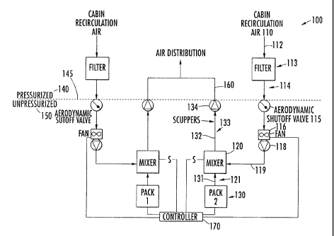
Figure 2 is a schematic diagram of an aircraft air conditioning system
according to the present invention.
-5-
CA 02350978 2004-12-07
DETAILED DESCRIPTION OF THE PRESENT INVENTION
The present invention now will be described more fully hereinafter with
reference to the accompanying drawings, in which preferred embodiments of the
invention are shown. This invention may, however, be embodied in many
different
forms and should not be construed as limited to the embodiments set forth
herein;
-Sa-
CA 02350978 2001-06-18
rather, these embodiments are provided so that this disclosure will be
thorough and
complete, and will fully convey the scope of the invention to those skilled in
the art.
Like numbers refer to like elements throughout.
Turning to Figure 2, there is shown a schematic view of an air conditioning
system 100 in accordance with the present invention. As shown, the air
conditioning
system 100 is particularly advantageous for use in commercial airplanes that
operate
at high altitudes. However, the air conditioning system can have other forms
and be
used in other applications, such as in other types of aircraft, without
departing from
the spirit and scope of the present invention. In addition, the system 100 is
capable of
equally efficient use during both high altitude cruising flight and on the
ground. For
ease of explanation, each like component will be designated with a singular
reference
number. However, the system 100 may include more than one component. For
example, the embodiment of Figure 2 includes two of substantially all the
components.
Figure 2 illustrates the system 100 as used in an aircraft having a
pressurized
area 140 and an unpressurized area 150 and defining a pressure bulkhead 145
therebetween. Although the system 100 is shown as a singular unit, the system
may
be designed such that separate systems are provided for individual zones
within the
pressurized area 140. As such, separate temperatures may be maintained for
each
zone to ensure comfort and efl:iciency.
According to the present invention, recirculation air 110 is drawn from the
pressurized area 140, such as a passenger cabin, cockpit, or cargo area, into
a
collecting duct 112. In this regard, a fan 116 is generally disposed in fluid
communication with the collecting duct 112 to draw air from the pressurized
area 140.
In one embodiment, the fan 116 is located inside the pressurized area 140,
but, more
preferably, the fan is located in the unpressurized area 150 to allow easier
maintenance access and to reduce fan noise transmission to the passenger cabin
or
other locations inside the pressurized area. The recirculation air 110
typically has a
relatively high moisture content and a raised temperature. In one embodiment,
the
recirculation air 110 is filtered through a filter 113 disposed within the
collecting duct.
The filter removes particles, such as odor components and disease carriers,
e.g.
viruses, germs, bacteria, and other contaminants, from the recirculation air
110. In
one embodiment, the system 100 also includes carbon dioxide strippers (not
shown)
-6-
CA 02350978 2001-06-18
disposed within the collecting duct 112. The filtered recirculation air is
then routed
through a transfer duct 114 across the pressure bulkhead 145 and through an
aerodynamic shutoff valve 115.
The aerodynamic shutoff valve 115 is located in the unpressurized area 150
S proximate the pressure bulkhead 145 and adapted for protecting against
decompression of the pressurized area 140 due to pressure loss downstream of
the
shutoff valve 115 in the unpressurized area. In one advantageous embodiment,
the
shutoff valve 115 comprises a mechanical butterfly valve having an offset
shaft and a
spring-loaded flapper. The flapper is spring-loaded to be set at a fully open
position
during normal operation and aerodynamically loaded in a fully closed position
at a
preset pressure differential across the flapper. Other types of similar
valves, such as
an aerodynamic shutoff valve with an electrical override actuator, can also be
used.
Thus, the shutoff valve 115 permits a flow of recirculation air 112 to pass
through the
shutoff valve, but as the flow increases and the pressure differential across
the flapper
I S increases the flapper will become loaded such that the shutoff valve 115
will be fully
closed when the preset pressure differential across the flapper is reached.
After
passing through the shutof~valve 115, the recirculation air 110 is delivered
to a
relatively small mixer 120 via a check valve 118 and delivery duct 119.
The system 100 also includes an air conditioning pack 130 for properly
conditioning fresh air 121. Air may be provided to the air conditioning pack
130 from
various sources. In one embodiment, for example, the source of air (not shown)
for
the air conditioning pack may be the compressor of a gas turbine engine, or an
auxiliary power unit, such that relatively high temperature, high pressure air
is
supplied to the air conditioning pack for treatment. In one embodiment, the
pack 130
is traditionally a combination of heat exchangers, compressors, and turbines
that are
known in the art, although other types of air conditioning packs can be
employed.
The pack 130 provides the fresh air 121 to the mixer 120 via a transfer duct
131 for
mixing with the recirculation air 110. Alternatively, the pack 130 can be
directly
connected to the mixer 120. In order to maintain pressure equilibrium, the
volume of
fresh air provided by the pack 130 is substantially equal to a volume of
leakage air
(not shown) that is removed to the environment outside the aircraft. Thus,
leakage air
is constantly replenished in the pressurized area 140. Eu~ther, in order to
minimize
CA 02350978 2001-06-18
the required amount of fresh air 121, the recirculation air 110 is mixed with
the fresh
air 121.
Advantageously, the mixer 120 is located in the unpressurized area 150 of the
aircraft proximate the air conditioning pack 130. In particular, the mixer 120
is
disposed between the delivery duct 119 and the transfer duct 131 and is
adapted for
mixing the relatively warm, moist recirculation air 110 and the cold, fresh
air 121
from the air conditioning pack 130. The mixer 120 obviates the need for a
large mix
manifold and associated ducting present in conventional systems and reduces
weight
and noise. The mix manifold and the associated ducting present in conventional
systems can occupy up to a volume of about 400 ft3, whereas the present
invention
occupies about one third of the volume occupied by conventional systems.
Moreover,
locating the mixer 120 in the unpressurized area 150, such as a portion of a
pack bay
111, allows easy maintenance access.
The air quality is monitored and controlled by a control unit 170. Although
the control unit 170 is depicted to be in the unpressurized area 150, the
control unit
may be in the pressurized area 140, if so desired. A sensor S is operatively
connected
to the mixer 120 and adapted for detecting conditions such temperature. The
control
unit 170 is operatively connected with and controls the pack 130 and fan 116
to
maintain air flow in the pressurized area 140 according to a desired
temperature
setting therein, taking into account the conditions detected by sensor S.
The control unit 170 generates appropriate control signals, whereby the status
of the system 100 is constantly monitored and correspondingly controlled when
the
system is in operation. Accordingly, the control unit 170 effectively
maintains
desired conditions through appropriate control signals to the pack 130 and/or
fan 116.
As known in the art for operating in a humid environment, the air conditioning
pack 130 often cools the fresh air 121 such that ice particles become
suspended
therein, which is disadvantageous if left unaddressed. The air conditioning
system
and method of the present invention address this problem by mixing the
recirculation
air 110 with the fresh air 121 at the mixer 120, which is located proximate
the air
conditioning pack 130 at which the ice particles suspended in the fresh air
121 have
minimal size. The mixer 120 mixes the two air flows 110, 121 to produce a
resultant
air flow 133 having a temperature that is sufficiently high such that the ice
particles
are substantially eliminated. More specifically, ice particles suspended in
the fresh air
_g_
CA 02350978 2001-06-18
121 are melted and condensed into tiny water droplets, which are then
collected in
downstream ducting 132 prior to entering air distribution ducts 160.
Advantageously, the mixer 120 is designed to swirl the resultant air flow 133
such that the tiny water droplets combine into larger droplets, which are then
removed
with conventional scuppers and discharged through drainage duct 135. More
specifically, the downstream ducting 132 is extended a relatively longer
distance than
the ducting, if any, of the conventional system 10 (See Figure 1). By
lengthening the
downstream duct 132 after the mixer 120, the present system 100 advantageously
obviates the need for a heat exchanger or other device to melt ice particles
and
provides an improved collection area that allows the tiny water droplets
suspended in
the resultant air flow 133 to combine into larger droplets as the resultant
air flow
travels through the downstream duct 132. The droplets are then collected by
the
scuppers which are operatively connected to the drainage duct 135, where the
droplets
are discharged from the aircraft. However, the droplets may also be used for
other
1 S purposes, such as to enhance heat exchanger cooling.
The resultant air flow 133 passes through the pressure bulkhead 145 via a
check valve 134 and into the air distribution ducts 160. In one embodiment,
the check
valve 134 is a mechanical flapper check valve. The check valve 134 protects
against
depressurization of the pressurized area 140 due to a duct rupture or the like
in the
unpressurized area 150.
A method of air conditioning an aircraft enclosure is also provided. In
particular, the method comprises providing a flow of recirculation air 110
from the
pressurized area 140 to the unpressurized area 150 through a first air duct
comprising
one or more of the collecting duct 112, transfer duct 114, and delivery duct
119. The
pressurized area is protected from depressurization by passing the flow of
recirculation air 110 through a valve, such as the aerodynamic shutoff valve
115. The
flow of recirculation air 110 is then mixed with a flow of cooling air, namely
the fresh
air 12l from the air conditioning pack 130, so that the resultant air mixture
133 is
formed having a temperature such that ice particles are melted or
substantially
eliminated.
Advantageously, the mixing step is performed in the unpressurized area 150 of
the aircraft without a conventional mix manifold. As described in detail
above,
mixing in this manner creates more pressurized area 140 that can be used for
-9-
CA 02350978 2001-06-18
passengers, cargo, or equipment. In addition, placing the mixer 120 in the
unpressurized area 150 reduces noise in the passenger compartment and improves
ease of maintenance. Other advantages are also realized, such as less weight.
After
mixing, the resultant air mixture 133 is passed through a second air duct
comprising
the downstream ducting 132 and air distribution duct 160. As described above,
the
downstream ducting 132 is sized and adapted for removing moisture, such as
water
droplets, from the resultant air mixture 133. The resultant air mixture 133 is
then
supplied to the pressurized area 140 through the air distribution duct 160 so
as to
maintain in the pressurized area, including the passenger compartment, at the
desired
temperature without generating a fog, snow, or water in the aircraft.
From the foregoing it will be seen that there has been shown and described an
aircraft air conditioning system and method that provide several advantages.
The use
of the system and method eliminates the need for reserving a large space in
the
pressurized area for a conventional mix manifold. The space can thus be used
for
revenue cargo, passengers, and/or other equipment installations. Other
benefits
include better management of ice from the air conditioning pack and downstream
ducting, improved water removal from the resultant air mixture using
lightweight
scuppers in the downstream ducting and noise improvement by isolating the
mixer
and associated fan components further from the passenger cabin. While
particular
embodiments of the invention have been shown and described, it will be
understood
that the invention is not limited thereto since modifications may be made by
those
skilled in the art, particularly in light of the foregoing teachings. It is
therefore
contemplated by the following claims to cover any such modifications and
incorporate those features which constitute the essential features of these
improvements within the spirit and scope of the invention.
-10-