Note: Descriptions are shown in the official language in which they were submitted.
CA 02351029 2001-06-15
DEVICE, SYSTEM AND METHOD FOR FLUID ADDITIVE
INJECTION INTO A VISCOUS FLUID FOOD STREAM
Field of the Invention
The present invention relates to introducing a fluid additive into a
relatively more
viscous fluid particularly when the fluid is a food composition extrudate.
Specifically, in
one aspect, the present invention relates to dividing a fluid food extrudate
mass flow into
a plurality of subflows eacli traveling through their own corresponding
passageway. Each
subflow is then cross-sectionally partitioned wherein a fluid additive is
dispersed
throughout each subflow.
Background of the Invention
Food products are commonly in sorne type of fluid form during and/or after
processing. Extruders are often used to process various types of food
products. Extruders
axe desirable because they can.produce a large amount of a fluid food, which
may be a
food dough, for example, and more specifically a cooked food cereal dough in.
a. short
period of time. Moreover, it is advantageous to divide the fluid food
extrudate or other
2C mass food flow into a multiplicity of extrudate subflows by splitting the
mass flow and
directing these extrudate subfLows into and through a plurality of
corresponding separate
passageways. This enables each extrudate substream to be further manipulated
and
processed. For example, an additive injection device can then izacorporated
into each
passageway thereby enabling a suitable type and quantity of fluid additive to
be
2~ introduced into the extrudate subflow. Additives can be introduced to
enhance the flavor,
color or texture of the final food product. Thus, either a single food product
with one or
more desired characteristics (i.e., a ready-to-eat cereal of a desired color
or with azi
assortment of differently flavored and/or colored pieces, for example) or a
variety of
distinct food products (i.e., an array of distinct snack foods derived from
the common
30 extrudate mass flow) can be produced by dividing the extrudate mass flow
into subflows.
However, obtaining a desired degree of mixing or a homogenous miacture after
introducing a fluid additive into a relatively viscous fluid food extrudate
subflow or other
fluid food product is troublesome. Typical food dough extrudates may have a
viscosity in
CA 02351029 2001-06-15
2
the range of from about 200.000 to 1,000,000 eentipoise, far example. Upon
introduction
into a fluid food exirudate, a typically less viscous fluid additive (sucli as
a colorant or
flavorant) has a tendency to migrate to the exterior periphery of the
extradite where the
additive tends to pool without blexzding with the food extradite. This pooling
at the
extrudate's periphery prevents adequate blending of the additive throughout
the extradite
mass by static mixers or other mixers located downstream from the additive
injection
point leaving undesirable pockets or areas of relatively high additive
concentration in the
extradite mass.
Dividinb a fluid food extradite mass flow into subflows and subsequently
introducing a fluid food additive has inherent shortcomings in addition to
pooling or
insufficient mixing. Introducing an additive injection device into the cross-
sectional flow
of the evtrudate substream can substantially increase the pressure drop along
the length of
the passageway where the injection device is present. This increases the
overall
resistazzce in the system. When the original extradite mass flow is divided
ixlto a plurality
1 ~ or many subflows, each travelling through a corresponding separate
passageway, the
additional energy required to drive the highly viscous fluid food extradite to
system's end
can be substantial. Moreover, providing an in.dependezzt additive supply for
each additive
iztjection device incorporated within each passageway makes it difficult to
obtain a
mliform introduction of additive in each of a plurality of extradite subflow
passageways.
A need exists to more uniformly introduce the same amount of additive across a
plurality of food extradite subflows travelling through separate passageways.
A need
also exists to more effectively reduce pooling when additive is introduced.
Finally, a
need exists for an additive injector device that can be easily and readily
cleaned and/or
sanitized.
Summary of the Invention
To avoid peripheral pooling, fluid additives are introduced by inserting an
additive
injector into the passageway perpendicular to the longitudinal axis of the
fluid food
extradite subflow. This partitions the subflow mass prior to the introduction
of the
additive. Splitting or partitioning has the advantage of reducing the amount
of static
n11x111g required to blend the additive in the passageway which consequently
lowers the
overall pressure drop of the device, In this configuration, the additive is
dispersed in the
CA 02351029 2001-06-15
3
center of the extrudate mass subflow thereby offsetting the tendency of the
additive to
migrate and pool on the extrudate's outer periphery.
In accordance with one aspect of the present invention, an apparatus for
injecting
a fluid additive into a viscous fluid food flow stream is provided. The
apparatus includes
a passageway having an interior and axe exterior, including an interior wall,
which
passageway is suitable to accommodate a fluid food flow, which may be a cooked
cereal
dough, for example, or other material, through the interior of the passageway.
Structure
is disposed in the passageway for injecting a fluid additive iuato the fluid
food flow in the
passageway. The structure in accordance with the invention for injecting the
fluid
additive can be streamlined to minimize the pressure drop across the injecting
structure.
In addition, the injecting device may include structure to preventing fluid
injected by the
injector from contacting the interior wall of the passageway. Such action
prevents
unwanted pooling or accumulation of additive fluid at the outer portions of
the fluid food
stream, which can result in an unacceptable or undesirable product.
The fluid additive can be any fluid additive as desired, and may include a
colorant,
flavor; food supplement or any other desired fluid food additive.
In accordance with another aspect of the present invention, the stnlcture for
injecting the fluid additive into the relatively viscous fluid food stream
includes a fluid
additive manifold located within the passageway, which zz~anifold may be
mounted within
the passageway. The manifold may be contained within an annular body or other
shaped
body or portion thereof as desired. A plurality of elongated ribs extend from
the manifold
and extend transversely across at least a portion of the passageway. Each of
the ribs may
have a downstream surface and a streamlined upstream surface to minimize
pressure loss
across the injector device. Generally, the manifold will have an internal
fluid additive
supply channel, with each of the ribs having an internal fluid additive or
extending along
an axial length of the rib that is in fluid communication with the channel and
with the
interior of the passageway. Communication between the channel and the interior
of the
passageway is achieved through a suitably configured aperture located along a
central
portion of the downstream portion of the rib and spaced transversely from the
interior
wall of the passageway. The aperture may be configured as an elongated slot.
Downstream-extending fins can be located between the interior wall of the
passageway and the ends of the aperture or slot aperture. Typically, a pair of
such fins
CA 02351029 2001-06-15
4
will be provided for each elongated slot aperture for preventing fluid
injected through the
opening or slot and into the viscous fluid food flow within the passageway
from
contacting the interior wall of the passageway. In this manner, unwanted
pooling or
accumulation of the fluid additive along the wall of the passageway is
prevented. Such
pooling or migration to the interior wall of the passageway is undesirable
because it is
very difficult to properly mix, thereby creating undesirable concentrations of
the additive
fluid in such areas.
In accordance with another aspect of the present invention, the passageways in
the
fluid injector device are straight and have an exterior line of sight access
to permit such
passages to be readily cleaned. This is particularly advantageous for various
types of
food ztzaterials that become hardened arzd have a strong adherence to metal
parts,
including cooked and dried cereal dough_
Preferably, the ratio of the interior diameter of the passageway to fin width
is in
the range of from about 6 to about 10 and the ratio of the interior diameter
of the
passageway to the fin length is in the range of from about 3 to about 1 S.
Typically, the ribs have an internal passageway or bore that extends along an
axial
length of each rib that is relatively large in volume compared with the area
of the aperture
through which the fluid additive can be injected into the passageway. Such an
arrangement facilitates the relatively uniform discharge of fluid throughout
the length of
the aperture or apertures located in the rib.
In accordance with another aspect of the present invention, a system is
provided
for dispersing a fluid additive into a relatively viscous fluid food flow
stream. The
system comprises a passageway having an interior and an exterior and including
an
interior wall. The passageway is suitable to accommodate a fluid food flow
through the
interior of the passageway. A fluid additive injection device is associated in
an operative
relation with the intezior of the passageway for injecting a fluid additive
into a fluid food
flow in the passageway. The fluid additive injection device includes a fluid
additive
manifold, a plurality of elongated ribs extending from the manifold and which
extend
transversely across at least a portion of the passageway. The manifold has an
internal
fluid additive supply channel and each of the ribs has an internal fluid
additive bore
extending along an axial length of the rib in .fluid communication with the
channel and
with the interior of the passageway through a rib aperture preferably located
along a
CA 02351029 2001-06-15
central portion of the downstream surface of the rib, face or portion, which
aperture is
spaced transversely from the interior wall of the passageway. A fluid additive
supply
source is in fluid communication with the fluid additive manifold. A pump is
provided
;tor supplying a constant amount of fluid additive from the supply source to
the manifold
without utilizing a flow control valve. This can be accomplished in a number
of ways,
including utilizing piping of equal length and diameter from the pump to each
of a
plurality oFinjection devices that may be utilized. Finally, a fluid food
mixer is disposed
in the passageway downstream of the food additive injection device for mixing
the
additive to a desired degree. In accordance with the present invention,
incomplete mixing
is contemplated to provide a swirled or ruarbled effect yr varied
concentration of the fluid
food additive, which may be a colorant.
In accordance with another aspect of the invention, a fluid food flow stream,
which may be obtained from the outlet of a Food extruder, is directed to the
system in
accordance with the invention which can include structure for splitting the
main flow
stream into a plurality of substreams for further processing, including the
introduction of
a desired fluid additive. In connection with this aspect of the invention, a
plurality of
passageways can be provided with each passageway having one of the fluid
additive
injection devices. Structure is provided for supplying an equal amount of the
fluid
additive to each of the additive injection devices without a flow control
valve or other
?0 adjustable flow control structure or mechanism.
In accordance with another aspect of the invention, the struetttre for
supplying the
Thud additive to each of the additive injection devices includes apiping
system and a
single pump. The piping system is in fluid communication with each of the
manifolds of
the t7uid additive injection devices, including a separate delivery pipe to
each manifold,
with the piping system being configured so that the flow rate of the fluid
additive at a
given pump output is the same to each manifold.
In accordance with another aspect of the present invention, a plurality of
passageways, each containing a fluid additive injection device, is provided,
which may be
an even number of passageways with a separate pump and piping system supplying
a
a0 single pair of fluid additive injection devices.
In accordance with still another aspect of the present invention, a method of
injecting a fluid additive into a relatively viscous fluid food stream
traveling in a
CA 02351029 2001-06-15
6
passageway is provided. The passageway has an interior wall in which the
injected fluid
additive avoids contact on the interior wall of the passageway. In accordance
with the
method. a fluid additive injection device is provided and associated in
operative relation
with the passageway for injecting the fluid additive into the fluid food flow.
The
injection device can be as previously described and may include a fluid
additive manifold,
a phtrality of elongated ribs extending from the manifold and which extend
transversely
across at least a portion of the passageway. The manifold tray have an
ix~,temal fluid
additive supply channel, with each of the ribs having an internal fluid
additive bore that
e;ctends along an axial length of the rib in fluid cozn~munication with the
channel and with
the interior of the passageway through a rib aperture located along a central
portion of the
downstream portion of the rib and spaced transversely from the interior wall
of the
passageway. In addition, a pair of elongated fins may be associated with each
rib and
disposed between the interior wall and the end of a rib aperture, which fins
extend
downstream of their respective rib for preventing fluid injected through the
slot from the
manifold and into the passageway from contacting or pooling along the interior
wall of
the passageway. The method further includes passing the relatively viscous
fluid food
through the passageway and injecting a fluid additive into the fluid additive
injection
device, through the rib apertures of the injection device and into the viscous
fluid food.
the fins preventing the fluid additive from contacting or pooling along the
wall of the
passageway.
In addition, the present invention provides for a system and method of
introducing
a uniform amount of additive across a plurality of subflow passageways. A
positive
displacement pump capable of ge~oerating pressure in excess of each subflow
passageway
is connected between the additive source and each additive injection cam-idge
located in
the subflow passageways. Tubing or piping between the pump and each subflow
passageway may include a suitable restriction or fined diameter for adjusting
the pressure
drop between the pump and each additive injection cartridge. For example, a
narrow
diameter tube diameter could be used to connect the pump to a subflow
passageway that
is located closer to the pump than another subflow passageway located further
from the
pump wherein a wider diameter tube or pipe could be used to connect the pump
to the
longer subflow passageway. Consequently, the additive flow rate into each
additive
injection cartridge can be uniform without a flow control valve. This ensures
that the
CA 02351029 2001-06-15
7
amount of additive dispersed throughout each extrudate subflow is the same,
thereby
producing a uniform food product yield from the plurality of subflow
passageways.
Alternatively, the fluid additive delivery system can consist of a relatively
large
diameter pipe that supplies the individual injector cartridges. Preferably,
any pip~g that
connects the large diameter pipe with the individual injector cartridge is of
relatively the
same length and diameter.
Alternatively, when a uniform additive blend across all extrudate subflows is
not
desired, one embodiment of the present Invention provides for a plurality of
pumps
wherein the number of pumps is at most one less than the number of subflow
passageways. Here, the pressure drop across each additive injection cartridge
need not be
w~iforrn. With this acrsnge~mextt, one pump can provide additive to two or
more subflow
passageways. Thus, different additives may be introduced to different subflow
passageways or varying amounts of the same additive may be introduced to
different
subflow passageways.
The present invention further provides for an additive injection cartridge
that
uniformly disperses additive throughout each corresponding extzudate subflow.
The
additive injection cartridge may be disk-shaped and partitions Lhc extrudate
subtlow by
means of a plurality of parallel ribs which are positioned perpendicular to
the direction of
the ex~udate subflow in each passageway. In a preferred embodiment, the
upstream
?0 surface of each rib comes to a point wherein the apex of the point
partitions the oncoming
subflow. This apex reduces the friction between the ribs and the subflow
during
partitioning, thereby assisting to reduce the pressuze drop across the
additive injection
cartridge.
.Another aspect of the invention provides fins on the downstream surface of
each
~ rib. These fins are important in restricting the migration or flow of the
additive fluid to
the exterior of the food stream before the extrudate-additive combination
reaches the
static mixers.
According to a fiu-ther aspect of the present invention, bores within the ribs
extend
through the disk with orifices on each end. This allows for easy maintenance
and
~ 0 cleaning of the rib interior.
CA 02351029 2001-06-15
8
Brief Description of the Drawings
FIG. 1 is a sectional side view of an apparatus for adding a fluid additive
into a
viscous fluid food stream in accordance with the invention;
FIG. 2 is a sectional plan view of the apparatus ofFIG. 1 along line 2-2;
FIG. 3 is a schematic flow diagram for injection of a fluid additive;
FIG. 4 is an alternative schematic flow diagram for injection of a fluid
additive;
FIG. 5 is a perspective view of a fluid additive injector device in accordance
with
the invention;
F1G_ 6 is a sectional view of the injector device along line 6-6 of FIG. S;
FIG. 7 is a rear elevation view, partly in section, of the injector device of
FIG. 5;
FIG. 8 is a front elevation view of the injector device of FIG. S;
FIG. 9 is a sectional view of the injector device along line 9-9 of FIG. 7:
FIG. 10 is a frasmentary sectional view of the injector device along line 10-
10 of
1 ~ FIG. 8; and
FIG. 11 illustrates an alternative embodiment of the portion of the injector
device
shown in FIG. 10.
Detai led Description of the Invention
Referring now to the drawings generally, and in particular to FIG. l, there is
illustrated a food processing device 10 in accordance with the present
invention. Device
10 is ideally suited for processing cooked cereal dough, which is typically a
relatively
viscous .fluid_ Such doughs typically are in the viscosity range of from about
200,000 to
about 1.000,000 centipoise. The dough is processed to form a ready to eat
(RTE) cereal.
5 Upstreann of device 10 is an extruder cooker (not shown) of standard
construction.
Such devices are well known in the art. The extruder cooker produces a
viscous, plastic
cooked cereal dough which is fed to food processing device 10.
Fovd processing device 10 includes an adapter plate 12 for interfacing device
10
with the extruder cooker, an inlet transition plate 14, a fluid additive,
injector cartridge
flange 1G, fluid additive injector cartridge 18, a static mixer assembly 20,
an outlet
transition plate 22, breaker plates 24 and a die plate 26. A suitable cutter
assembly (not
shown) can be utilized downstream of die plate 26 to divide the extruded food
as it exits
CA 02351029 2001-06-15
9
die plate 26 into desired lengths which may be subjected to further
processing, such as
formation into flakes, sheets or puffed pieces.
Inlet transition plate 14 provides a constricted diameter for fluid food
leaving the
extruder cooker at the inlet to food processing device 10. A constricted
diameter
increases the pressure in food stream S which in this embodiment is split into
six food
substreams 5', as indicated by arrows A, for ease of processing, in which the
streams 5'
travel in the direction indicated by arrows B in FIG. 1. The split into six
streams S'
occurs as the fluid food dough travels into fluid additive cartridge flange
16. Flange 16
includes a center cone section 28 which facilitates the flow of dough into the
six separate
1 U substreams 5', helping to prevent the formation of any void spaces.
Inlet transition plate 14 is secured to adapter plate 12 by means of a
suitable
fastener. which may be threaded fasteners 30. Similarly, inlet transition
plate 14, fluid
additive cartridge flange I6, static mixer assembly 20, transition plate 22
and die plate 26
are also secured together, as illustrated in FIG. 1 by means of suitable
fasteners such as
1 ~ threaded fasteners 32, 34 and 36.
Fluid additive cartridge flange 16 is disc-shaped and includes recesses 38
adapted
for mounting fluid additive injector cartridges 18 therein, as shown in FIGS.
1 and 2. A
fluid additive supply line 40 is provided for each injector cartridge 18.
Supply lines 40 in
flange 1 G are preferably straight to readily permit cleaning, which may
include cleaning
?U by drilling or boring through any accumulated material or residue in supply
lines 40.
Flange 16 defines six passageways 42 in conjunction with injector cartridge 18
and static
nuxer assembly 20.
Static mixer assembly 20 is composed of an elongated tubular structure 44 in
which is disposed static mixer fligtzts 46, shown schematically izi FIG. 1.
Tubular
structure 44 is jacketed with jacket 48 to permit heating or cooling as
desired with an
appropriate fluid through inlet ports 50 and outlet port 52. A sufficient
length of mixer
flights 46 are provided to achieve the desired degree of mixing for a
particular product,
which may range from light mixing to complete mixing. Less than complete
mixing can
produce a marbled or swirled effect, which can be an appearance (if colorant
is utilized as
;U the fluid additive) and/or a concentration gradient. Assembly 20 also
includes
appropriate mounting flanges 54 and 56.
CA 02351029 2001-06-15
Mounted at the discharge end 20' of mixer assembly 20 is transition plate 22,
which slightly expands passageways 42 from an upstream to downstream
direction_ The
mixed fluid food with the injected fluid additive then travels through breaker
plate 24
which is composed of a plurality of apertures, after which the fluid food
travels through
die plate 26 for division into individual lengths or ropes, which can then be
divided into
discrete lengths or pellets, to be processed further as desired, such as by
flaking, sheeting
or puffed pieces.
Referring to FIGS. 5-11, various aspects of fluid additive injector cartridge
18 are
illustrated in detail. Cartridge I8 includes a fluid additive manifold 58
which is a straight
10 bore having an external line of sight access 58' to readily permit cleaning
such as by
boring or drilling, for example. Manifold 58 is aligned with its respective
fluid additive
supply line 40 in cartridge flange 16. Such alignment is facilitated by
locator pins or
dowels 60 in cartridge 18 and complementary holes (not shown) of recess 3S of
flange 16,
so that when cartzidge 18 is in position as shown in FIG. 1 in flange 16, pins
60 are
1 ~ contained in the complementary holes of flange 1 G.
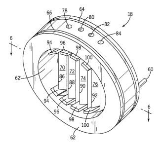
Injector cartridge I S may have an annular body 62 in wlucli manifold 58 is
located. Grooves 64 and 66 extend around the outer periphery of annular body
62 to
contain 0-rings 68 and thereby provide a fluid-tight seal when mounted in
flange 16 as
hereinafter described.
A plurality of ribs 70, 72, 74 and 76 extend from one side of the annular
opening
to the other as shown in FIGS. 5, and 7-9. Each rib has a longitudinally
extending bore
78, S0, 82 and 84, respectively, each of which cozt~municates with manifold 58
and
extends through the opposite side of annular body 62, as shown in FIGS. S-S.
Bores 78,
80, S2 and 84 are straight and provide as external line of sight access where
bores 78, 80,
?5 82 and 84 extend through annular body 62 as shown in FIG. 5 to readily
penxzit cleaning,
including by drilling or boring, for example. O-rings 68 provide a fluid-tight
seal to
prevent any fluid in bores 78, 80, 82 and 84 from entering passageway 42 when
injector
cartridges 18 are installed in cartridge flange l6.
Ribs 70, 72, 74 and 76 preferably have an upstream streamlined shape as shown
in
FIG. 6 so that a viscous fluid food (which may be a cereal dough) readily
passes around
and past ribs 70, 72, 74 and 76. In this case, the streamlined shape is a
wedge shape with
the upstrEam leading edge 70', 72', 74' and 76' of ribs 70, 72, 74 and 76
being wedge-
CA 02351029 2001-06-15
11
shaped having an angle of about 90°. For the illustrated embodiment and
recited
din~ensio~is, the point of the wedge shape has a radius of curvature that is
about 0.060
inches, as indicated by R in FIG. 10. In addition, ribs 70, 72, 74 and 7G have
a height HF
as shown in FIG. 10 of about 0.313 inches.
The downstream side of ribs 70, 72, 74 and 76 each have an elongated slot
aperture 86, 88, 90 and 92, respectively, that coznmmo.icate with bores 78,
80, 82 and 84,
respectively. The volume of bores 78, 80, 82 and 84 is relatively large
compared to the
area of slot apertures 86, 88, 90 and 92.
Each slot aperture 86, 88, 90 and 92 is elon'ated and extends longitudinally
of
respective rib 70, 72, 74 and 76, and extends along a central portion of the
downstream
facing side of such ribs. In one embodiment, far an inner diameter annular
body 62 of
about 3 inches, each of slot apertures 86, 8S, 90 and 92 is about 0.020
centimeters wide
and the diameter of each of bores 78, 80, 82 and 84 is about 0.188 inches.
Ribs 70, 72, 74
and 76 have a spacing therebetween of about 0.219 inches with the ntah~rt~um
spacing
between end ribs 70 and 76 and the interior of annular body 62 as indicated by
arrows C
being about 0.472 inches.
Each rib 70, 72, 74 and 76 on the dow~astream~ side thereof has a pair of fins
94,
96; 9S and 100, respectively, that extend downstream from the ribs and
longitudinally of
annular body 62 and thus of passageway 42 when mounted in food processing
device 10.
Preferably, each end of slot apertures 86, S8, 90 and 92 terminates about 3/32
inch
before each of fins 94, 96, 98 and 100.
Fins 94, 96, 98 and 100 preferably are slightly ctuved and thus are concentric
to
imer diameter curvature 62' of annular body 62. In the illustrated
ert~boditnent of
FIGS. 5-10. fins 94, 96, 98 and 100 have a width of about 0.375 inches as
indicated by
arrow D and a height from the tip of rib 72 where aperture 88 is located of
about 0.25
inches, indicated by arrow H in FIG. 10. Fins 94, 96, 98 and 100 should have
sufficient
thickness for the desired structural rigidity for the intended operating
environment.
In addition, fins 94, 96, 98 and 100 are radially inwardly located
approximately
0.20 inches from the inner surface of annular body 62, for annular body 62
having a
diameter of about 3 inches.
Fins 94, 96, 98 and 100 have a rectangular prof le as shown in FIG. 10, which
is
preferred compared to other profile shapes, such as the triangular profile
shown in
CA 02351029 2001-06-15
12
FIG. 11, where like reference numerals represent like elements. The
rectangular profile
functions more effectively in keeping fluid injected out of bore 80 and slot
aperture 8S
from reaching the wall of passageway 42.
Preferably, for the illustrated embodiment, the ratio of the interior diameter
of
passageway 42 (and also interior annular diameter of annular body 62) to fin
width I~ is in
the range of fzom about 6 to 10 and the ratio of passageway 42 diameter to fin
length H is
in the range of from about 8 to about 15, as shown in FIG. 10.
Referring to FIGS. 3 and 4, there is illustrated various fluid additive
delivery
systems in accordance with the invention. More specifically, a fluid additive
delivery
system 102 in FIG. 3 includes a pump and pump manifold 104 (shown
schematically),
piping segments 106a-f, and six injector cartridges 18a-f. Pump I04 preferably
is a
positive displacement pump to reduce the chance that fluid food in passageway
42 would
travel into any of injector cartridges I 8a-f In one embodiment, the length of
piping
segments 1 OGa-f are of the same length, geoznetzy and diametez, so that
utuform fluid
additive flow rates are achieved without the use of any flow control valves or
other
adjustable flow control devices- Alternatively, for different lengths of
pipizig segments
106a-f longer segments can be of larger diameter, or shorter segments can be
of smaller
diameter or otherwise have fixed restrictions 108a-a therein to pzovide the
same flow rate
at a given pump output.
?0 Alternatively, different flow rates may be provided by providing for
different
pressure drops between pump 104 and injectors 18a-f as desired without an
adjustable
flow control valve or other adjustable flow controller.
Referring to FIG. 4, an alternate fluid additive delivery system is
illustrated
composed of three pumps and pump manifolds 1 l0a-c, pipizag segments 112a-f
aDd six
?5 injector cartridges 18a-f. Each of pumps 110a-c supplies a fluid additive
to two separate
injector cartridges 18a-f. The additive supplied by each pump may be the same
or
different as desired. Uniform or different flow rates can be provided as
described with
respect to FIG. 3.
Referring to FIG. 2, an alternate fluid delivery system is illustrated in
which a
_~ 0 pump (not shown) supplies the additive fluid under a desired pressure to
a relatively large
diameter pipe 114 (shown in fragmentary view) which is used to supply each of
fluid
CA 02351029 2001-06-15
13
additive delivery lines 40. Pipe 114 should preferably have a diameter of. at
least about
two to four or more times the diameter of one of delivery lines 40.
While the invention has been described with respect to certain preferred
embodiments, as will be appreciated by those skilled in the art, it is to be
understood that
the invention is capable of numerous changes, modifications and rearrangements
and such
changes, modifications and rearrangements are intended to be covered by the
following
claims.