Language selection

Search

Patent 2351160 Summary

Third-party information liability

Some of the information on this Web page has been provided by external sources. The Government of Canada is not responsible for the accuracy, reliability or currency of the information supplied by external sources. Users wishing to rely upon this information should consult directly with the source of the information. Content provided by external sources is not subject to official languages, privacy and accessibility requirements.

Claims and Abstract availability

Any discrepancies in the text and image of the Claims and Abstract are due to differing posting times. Text of the Claims and Abstract are posted:

  • At the time the application is open to public inspection;
  • At the time of issue of the patent (grant).
(12) Patent: (11) CA 2351160
(54) English Title: STRAPPING MACHINE HAVING AN EASY CLEAR SLACK BOX
(54) French Title: CERCLEUSE COMPRENANT UNE BOITE A DEBRIS FACILE A VIDER
Status: Deemed expired
Bibliographic Data
(51) International Patent Classification (IPC):
  • B65B 13/18 (2006.01)
(72) Inventors :
  • BOBREN, ALLAN J. (United States of America)
  • DEVINE, DARRYL M. (United States of America)
(73) Owners :
  • ILLINOIS TOOL WORKS INC. (United States of America)
(71) Applicants :
  • ILLINOIS TOOL WORKS INC. (United States of America)
(74) Agent: FINLAYSON & SINGLEHURST
(74) Associate agent:
(45) Issued: 2006-08-15
(22) Filed Date: 2001-06-21
(41) Open to Public Inspection: 2001-12-22
Examination requested: 2001-06-21
Availability of licence: N/A
(25) Language of filing: English

Patent Cooperation Treaty (PCT): No

(30) Application Priority Data:
Application No. Country/Territory Date
09/599,800 United States of America 2000-06-22

Abstracts

English Abstract

A strapping machine having a strap accumulator box with an easy access panel is provided. The strapping machine includes a lever that allows for the quick opening of the easy access panel and the quick clearing of the strapping machine of strap debris and jams. The strapping machine of the present invention further includes a lever for quick release of the access panel. The access panel is spring biased in a first closed position and, upon the clearing of strap debris and jams, the access panel is returned to its first closed position.


French Abstract

Une cercleuse possédant une caisse d'accumulateur de cerclage dotée d'un panneau d'accès facile. La cercleuse comprend un levier qui permet l'ouverture rapide du panneau d'accès facile et l'élimination rapide de la cercleuse des débris et autres bourrages. La cercleuse de la présente invention comprend de plus un levier d'ouverture rapide du panneau d'accès. Le panneau d'accès est actionné en une première position fermée et, lors de l'élimination des débris et bourrages, le panneau d'accès est retourné à sa première position fermée.

Claims

Note: Claims are shown in the official language in which they were submitted.


WHAT IS CLAIMED IS:

1. A strapping machine, having an easy clear strap accumulator box,
comprising:
a strapping machine housing;
a strap path;
a strap accumulator box, defined below said strap path, comprising a lower
assembly
and an assembly release lever;
said lower assembly being rotationally attached to said strapping machine
housing such
that upon the operation of said release lever, said lower assembly may be
rotated to an open
position and said accumulator box may be cleared of strap.

2. The strapping machine of claim 1, wherein said lower assembly is held in a
first closed
position by a biasing element.

3. The strapping machine of claim 2, wherein said biasing element is a spring.

4. A strapping machine, having an easy clear strap accumulator box,
comprising:
a strapping machine housing;
a strap path;
a strap accumulator box, defined below said strap path, comprising a lower
assembly
and an assembly release lever;
said lower assembly being rotationally attached to said strapping machine
housing and
biased by a spring in a first closed position, such that upon the operation of
said release lever,


said lower assembly may be rotated to an open position and said accumulator
box may be
cleared of strap and upon release of said lever, said lower assembly rotates
back to its first
closed position

6


Description

Note: Descriptions are shown in the official language in which they were submitted.


CA 02351160 2001-06-21
12324/881 S
STRAPPING MACHINE HAVING AN EASY CLEAR SLACK BOX
FIELD OF THE INVENTION
The present invention concerns a novel strapping machine having an easy clear
slack
box allowing the opening of the outer housing of a strapping machine to remove
excess strap
and strapping debris.
BACKGROUND OF THE INVENTION
The use of strapping machines causes debris from the strap material to
accumulate
within the strapping machine. It has been found that, due to the accumulation
of debris, the
strapping must be stopped often and the machine must be cleared so that it may
continue to be
operated. The accumulation of strap may cause the machine to jam and/or the
various parts that
create a path for the strap to be forced out of alignment. Misalignment of the
strap path often
results in the jamming of the strap machine and may cause damage to strap path
elements.
In most strapping machines presently in use, the machine must be disassembled
on
occasion during use and cleared of strap debris. Such disassembly, clearing
and reassembly,
while necessary, is time consuming and removes a strapping machine from its
strapping tasks.
It would be preferable to have a machine that would allow easy access to the
interior
of the machine so that it could be cleared of strap debris and jams without
having to
disassemble the machine and remove it from its strapping tasks for extended
periods of time.
2 0 Further, such a machine, due to the ease of opening the strap accumulator
box, would allow
for more prophylactic cleaning so that strap jams may mostly be avoided.


CA 02351160 2001-06-21
SUMMARY OF THE INVENTION
In accordance with the present invention, a strapping machine, having an easy
clear
-- strap accumulator box or slack box, comprising, a strapping machine housing
and a strap path
is provided. The strap accumulator box, defined below the strap path,
comprises an area for
strap and debris collection, a lower assembly or door, and a door release
lever. The lower
assembly or door is rotationally attached to the strapping machine housing
such that upon the
operation of the release lever the lower assembly may be rotated to an open
position allowing
the accumulator box to be cleared of strap debris.
In the preferred embodiment of the present invention, the lower assembly or
door of
the accumulator box is spring biased in a first closed position. The assembly
release lever may
be depressed, by hand or foot, to release the lower assembly door such that it
may be rotated
away from the accumulator box, allowing strap debris to fall from the
strapping machine, and
allow for the clearing of jams from the slack accumulator box and strap path.
In the preferred
embodiment of the present invention, depression of the release lever causes
the accumulator
box door to rotate open and release of the lever causes the door to rotate to
its default closed
position.
It may be seen that the accumulator box door may be maintained in an open
position,
by for example lever locking means, to allow for a more thorough inspection
and cleaning of
the strap accumulator area and the strap path. It is to be understood that
while the accumulator
2 0 box door of the present invention is located at the bottom of the
strapping machine, the daor
may be placed at the side of the machine and allow similar access to the
accumulator box, for
clearing and maintenance, without departing from the novel scope of the
present invention.
2

CA 02351160 2001-06-21
A more detailed explanation of the invention is provided in the following
description
and claims and is illustrated in the accompanying drawings.
BRIEF DESCRIPTION OF THE DRAWINGS
Figure 1 is a perspective view of a strap accumulator box, having a strap
clearing door
of the present invention in a first, closed, position.
Figure 2 is a side elevational view of the strap accumulator box of Figure 1.
Figure 3 is a perspective view of a strap accumulator box, having a strap
clearing door
of the present invention is a second, opened, position.
Figure 4 is a side elevational view of the strap accumulator box of Figure 3.
DETAILED DESCRIPTION OF THE
ILLUSTRATIVE EMBODIMENT
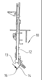
Referring to the drawing, Figures 1 and 2 show a strapping machine 10 having
strap
accumulator box 12, an open end 13, and a lower assembly or strap clearing
door 14 covering
said open end 13. A lever 16, attached to said strap accumulator box 12 and a
spring (not
shown), biasing said strap clearing door 14 in a first closed position, is
shown. Figures 3 and
4 show strapping machine 10 with strap clearing door 14 in a second open
position. It may be
seen, in Figure 4, that any loose strap material held in accumulator box 12
may freely fall from
2 0 strapping machine 10 when said strap clearing door 14 is opened.
When clearing of the strap accumulator box 12 is desired, strapping machine 10
is
stopped and lever 16 is depressed causing strap clearing door 14 to pivot down
on a hinge until
3

CA 02351160 2001-06-21
door 14 is open. As door 14 is generally at the bottom of the strapping
machine 10, excess
debris and strap pieces fall out of strapping machine 10 through open end 13
by gravity. When
door 14 is in an open position, the entire slack box 12 may be cleared of
debris and excess strap
material. When strap and debris have been cleared from the strap accumulator
box 12, door
14 may be returned to its first, closed position, upon the release of lever
16. Spring (not
shown) causes door 14 to return to cover open end 13, upon the release of
lever 16.
It may be seen that the operation of the easy clear strap box of the present
invention
may proceed with minimal interruption in the strapping process.
Although an illustrative embodiment of the invention has been shown and
described,
it is to be understood that various modifications and substitutions may be
made by those skilled
in the art without departing from the novel spirit and scope of the invention.
4

Representative Drawing
A single figure which represents the drawing illustrating the invention.
Administrative Status

For a clearer understanding of the status of the application/patent presented on this page, the site Disclaimer , as well as the definitions for Patent , Administrative Status , Maintenance Fee  and Payment History  should be consulted.

Administrative Status

Title Date
Forecasted Issue Date 2006-08-15
(22) Filed 2001-06-21
Examination Requested 2001-06-21
(41) Open to Public Inspection 2001-12-22
(45) Issued 2006-08-15
Deemed Expired 2013-06-21

Abandonment History

There is no abandonment history.

Payment History

Fee Type Anniversary Year Due Date Amount Paid Paid Date
Request for Examination $400.00 2001-06-21
Registration of a document - section 124 $100.00 2001-06-21
Application Fee $300.00 2001-06-21
Maintenance Fee - Application - New Act 2 2003-06-23 $100.00 2003-06-10
Maintenance Fee - Application - New Act 3 2004-06-21 $100.00 2004-06-04
Maintenance Fee - Application - New Act 4 2005-06-21 $100.00 2005-06-07
Final Fee $300.00 2006-05-26
Maintenance Fee - Application - New Act 5 2006-06-21 $200.00 2006-05-31
Maintenance Fee - Patent - New Act 6 2007-06-21 $200.00 2007-05-30
Maintenance Fee - Patent - New Act 7 2008-06-23 $200.00 2008-05-30
Maintenance Fee - Patent - New Act 8 2009-06-22 $200.00 2009-06-01
Maintenance Fee - Patent - New Act 9 2010-06-21 $200.00 2010-06-01
Maintenance Fee - Patent - New Act 10 2011-06-21 $250.00 2011-05-31
Owners on Record

Note: Records showing the ownership history in alphabetical order.

Current Owners on Record
ILLINOIS TOOL WORKS INC.
Past Owners on Record
BOBREN, ALLAN J.
DEVINE, DARRYL M.
Past Owners that do not appear in the "Owners on Record" listing will appear in other documentation within the application.
Documents

To view selected files, please enter reCAPTCHA code :


To view images, click a link in the Document Description column. To download the documents, select one or more checkboxes in the first column and then click the "Download Selected in PDF format (Zip Archive)" or the "Download Selected as Single PDF" button.

List of published and non-published patent-specific documents on the CPD .

If you have any difficulty accessing content, you can call the Client Service Centre at 1-866-997-1936 or send them an e-mail at CIPO Client Service Centre.


Document
Description 
Date
(yyyy-mm-dd) 
Number of pages   Size of Image (KB) 
Representative Drawing 2001-11-27 1 4
Abstract 2001-06-21 1 15
Description 2001-06-21 4 129
Claims 2001-06-21 2 33
Drawings 2001-06-21 1 32
Cover Page 2001-12-14 1 31
Representative Drawing 2006-07-17 1 4
Cover Page 2006-07-17 1 31
Assignment 2001-06-21 8 309
Correspondence 2006-05-26 1 32