Note: Descriptions are shown in the official language in which they were submitted.
CA 02351422 2001-05-18
WO 00/31928
METHOD AND SYSTEM FOR RESUMING
TRANSMISSION AFTER INTERRUPTION
BACKGROUND
PCT/SE99/02099 =
This invention relates generally to a method and system for transmitting data
in a
communication system. More particularly, this invention relates to a method
and system
for resuming transmission of data in a communication system after
interruption.
FIG. 1 is a block diagram of an exemplary cellular radiotelephone system,
including an exemplary base station 110 and a mobile station 120. Although
denoted a
"mobile station", the station 120 may also be another type of remote station,
e.g., a fixed
cellular station. The base station includes a control and processing unit 130
which is
connected to the a mobile switching center (MSC) 140 which in tum is connected
to a
PSTN (not shown). General aspects of such cellular radiotelephone systems are
known in
the art. The base station 110 handles a plurality of voice channels through a
voice
I S channel transceiver 150, which is controlled by the control and processing
unit 130.
Also, each base station includes a control channel transceiver 160, which may
be capable
of handling more than one control channel. The control channel transceiver 160
is
controlled by the control and processing unit 130. The control channel
transceiver I60
broadcasts control information over the control channel of the base station or
cell to
mobiles locked to that control channel. It will be understood that the
transceivers 150 and
160 can be implemented as a single device, like the voice and control
transceiver I70, for
use with control and traffic channels that share the same radio carrier.
The mobilc station 120 receives the information broadcast on a control channel
at
its voice and control channel transceiver 170. Then, the processing unit 180
evaluates the
received control channel information, which includes the characteristics of
cells that are
candidates for the mobile station to lock on to, and determines on which cell
the mobile
should lock. Advantageously, the received control channel information not only
includes
absolute information concerning the cell with which it is associated, but also
contains
relative information concerning other cells proximate to the cell with which
the control
channel is associated, as described for example in U.S. Patent No. 5,353,332
to Raith et
CA 02351422 2001-05-18
WO 00/31928 PCT/SE99/02099
-2-
al., entitled "Method and Apparatus for Communication Control in a
Radiotelephone
System".
Modern communication systems, such as cellular and satellite radio systems,
employ various modes of operation (analog, digital, dual mode, etc.), and
access
techniques such as frequency division multiple access (FDMA), time division
multiple
access (TDMA), code division multiple access (CDMA), and hybrids of these
techniques.
In North America, a digital cellular radiotelephone system using TDMA is
called
the digital advanced mobile phone system (D-AMPS), some of the characteristics
of
which are specified in the TIA/EIA/IS-136 standard published by the
Telecommunications Industry Association and Electronic Industries Association
(TIA/EIA). Another digital communication system using direct sequence CDMA is
specified by the TIA/EIA/IS-95 standard. There are also frequency hopping TDMA
and
CDMA communication systems, one of which is specified by the EIA SP 3389
standard
(PCS 1900). The PCS 1900 standard is an implementation of the GSM system,
which is
common outside North America, that has been introduced for personal
communication
services (PCS) systems.
Several proposals for the next generation of digital cellular communication
systems are currently under discussion in various standards setting
organizations, which
include the International Telecommunications Union (TTIn, the European
Telecommunications Standards Institute (ETSI), and Japan's Association of
Radio
Industries and Businesses (A.RIB). Besides transmitting voice information, the
next
generation systems can be expected to carry packet data and to inter-operate
with packet
data networks that are also usually designed and based on industry-wide data
standards
such as the open system interface (OSI) model or the transmission control
protocol/Intemet protocol (TCP/IP) stack. These standards have been developed,
whether
formally or de facto. for many years, and the applications that use these
protocols are
readily available. The main objective of standards-based networks is to
achieve
interconnectivity with other networks. The Internet is today's most obvious
example of
such a standards-based packet data network in pursuit of this goal.
CA 02351422 2001-05-18
WO 00/31928 PCT/SE99/02099
-3-
Advantages of introducing a packet data protocol in cellular systems include
the
ability to support high data rate transmissions and at the same time achieve a
flexibility
and efficient utilization of the radio frequency bandwidth over the radio
interface.
General Packet Radio Service (GPRS), which is the packet mode for the Global
System
for Mobile Communication (GSM) standard, is designed for so-called "multislot
operations" where a single user is allowed to occupy more than one
transmission resource
simultaneously.
An overview of the GPRS network architecture is illustrated in FIG. 2A.
Information packets from external networks enter the GPRS network at a GGSN
(Gateway GPRS Service Node) 10. A packet is then routed from the GGSN via a
backbone network,12, to a SGSN (Serving GPRS Support Node), 14, that is
serving the
area in which the addressed GPRS remote station resides. From the SGSN 14, the
packets.are routed to the correct BSS (Base Station System), in a dedicated
GPRS
transmission. The BSS includes a plurality of base transceiver stations (BTS),
only one
of which, BTS 18, is shown and a base station controller (BSC) 20. The
interface
between the BTSs and the BSCs are referred to as the A-bis interface. The BSC
is a
GSM specific denotation, and for other exemplary systems the term Radio
Network
Control (RNC) is used for a node having similar functionality as that of a
BSC. Packets
are then transmitted by the BTS 18 over the air interface to a remote station
21 using a
selected information transmission rate.
A GPRS register holds all GPRS subscription data. The GPRS register may, or
may not, be integrated with the HLR (Home Location Register) 22 of the GSM
system.
Subscriber data may be interchanged between the SGSN and the MSC/VLR 24 to
ensure
service interaction, such as restricted roaming. The access network interface
between the
BSC 20 and MSC/VLR 24 is a standard interface known as the A-interface, which
is
based on the Mobile Application Part of CCTTT Signaling System No. 7. The
MSC/VLR
24 also provides access to the land-line system via PSTN 26.
In most digital communication systems, communication channels are
implemented by frequency modulating radio carrier signals, which have
frequencies near
w CA 02351422 2001-05-18
WO 00/31928 PCT/SE99/02099 -
-4-
800 megahertz (MHZ), 900 MHZ, and 1900 MHZ. In TDMA systems and even to
varying extents in CDMA systems, each radio channel is divided into a series
of time
slots, each of which contains a burst of information from a user. The time
slots are
grouped into successive frames that each have a predetermined duration, and
successive
frames may be grouped into a succession of what are usually called
superframes. This
kind of access technique (e.g., TDMA or CDMA) used by a communication system
affects how user information is represented in the slots and frames, but
current access
techniques all use a slot/frame structure.
Time slots assigned to the same user, which may not be consecutive time slots
on
the radio carrier, may be considered a logical channel assigned to the user.
During each
time slot, a predetermined number of digital bits are transmitted according to
the
particular access technique (e.g., CDMA) used by the system. In addition to
logical
channels for voice or data traffic, cellular radio communication systems also
provide
logical channels for control messages, such as paging/access channels for call-
setup
messages exchanged by base stations and mobile stations. In general, the
transmission bit
rates of these different channels need not coincide, and the lengths of the
slots in the
different channels need not be uniform. The set of possible transmission bit
rates for a
channel is typically a limited integer value and is known to both the
transmitter and the
receiver which use that channel.
In cellular radio systcms, an air interface protocol is required in order to
allow a
mobile station to communicate with the base stations and a mobile switching
center
(MSC). The air interface protocol is used to initiate and to receive cellular
telephone
calls. A physical layer (Layer 1) defines the parameters of the physical
communications
channel, e.g., carrier radio frequency spacing, modulation characteristics,
etc. A link
layer (Layer 2) defines the techniques necessary for the accurate transmission
of
information within the constraints of the physical channel, e.g., error
correction and
detection, etc. A Radio Resource Control (RRC) Layer 3 defines the procedures
for
reception and processing of information transmitted over the physical
channels.
TIA/EIA/IS-136 and TIA/ELA/IS-95 for example specify air interface protocols.
The
°
- CA 02351422 2001-05-18
WO 00/31928 PCT/SE99/02099 =
-5-
functionality of a Layer 2 protocol includes the delimiting, or framing, of
Layer 3
messages, which may be sent between communicating Layer 3 peer entities
residing
within mobile stations and cellular switching systems.
The physical channel between the remote station and the base station is
typically
divided into time frames, as illustrated in FIG. 2B. The information unit
transmitted
during a time frame can be called a transmission block. In the next generation
systems,
data can be grouped into packets for transmission. One or several data packets
can be
transmitted within a transmission block.
At the Layer 2 level, a packet typically comprises a header part, an
information
part (I-part), and an error detection code part. To ensure safe receipt of a
long (mufti-line)
message, an Automatic Re-transmission request (ARQ) mode transaction may be
used.
According to the ARQ scheme, the header part typically includes information
used for
requesting re-transmission of corrupted packets. The error detecting part,
called the
Cyclic Redundancy Code (CRC), is used to determine if the rest of the packet
has been
corrupted in some way when transmitted on the channel. If so, a re-
transmission request
signal is transmitted to the transmitter, and the original data is re-
transmitted.
According to the ARQ scheme, only the frames that are not successfully
received
by the receiving entity need to be re-transmitted. However, since transmission
of a long
message may take a substantial amount of time, there might be a need to
interrupt the
ARQ Mode transaction, e.g., to transmit a more time critical message. The IS-
136
standard does not provide a technique for resuming a previously interrupted
ARQ Mode
transaction. Thus, according to the IS-136 standard, when an ARQ Mode
transaction is
interrupted, it is aborted and must be started all over again, from the
beginning of the
message being transmitted. This wastes bandwidth. The longer the message, the
higher
the risk of interruption and the greater the bandwidth wasted due to
interruption.
In addition, if transmission of the message is re-started on a channel
normally
occupied by other data, this leads to an interruption of other data. For
example, if the
message is transmitted on the Fast Associated Control Channel (FACCH), re-
starting
CA 02351422 2001-05-18 PCE 9 9 / 0 2 0 9 9
The Swe~lsh Patent Oitice
[PCT Intemation:~~ Appncatlon
transmission of the message leads to an unnecessary interruption of voice,
since the FACCH
uses the same space normally occupied by the voice.
U.S. Patent No. 5,745,695 describes a GSM cellular radio system with GPRS
capability in which data service is suspended while a non-data service is
executed. Following
termination of the non-data service, GPRS capability is resumed.
WO 97 15165 describes a method for improving the efficiency of the packet data
channel by providing means for interrupting transmissions from or to a first
mobile station so
as to allow a short message to be communicated between the communication
system and a
different mobile station
Thus, there is a need for a method and system for resuming transmission of
data after
interruption of transmission, without requiring that the transmission process
be started over.
SUMMARY
It is therefore an object of the present invention to provide a way of
resuming
transmission of data after interruption of transmission without requiring the
transmission process to be started over from the beginning.
In one aspect, the invention provides a method for resuming an ARQ Mode
transaction over a communication link between a transmitting entity and a
receiving entity
following an interrupt in the ARQ Mode transaction. The method includes the
steps o~ (a)
receiving, at the transmitting entity, an ARQ Status frame from the receiving
entity, the ARQ
Status frame having a data field that indicates a number, N, of ARQ frames
transmitted by the
transmitting entity and received by the receiving entity prior to the
interrupt in the ARQ
Mode transaction, and (b) resuming, at the transmitting entity, the ARQ Mode
transaction in
response to the ARQ Status frame received from the receiving entity, wherein
the ARQ Mode
transaction is resumed at the frame following the frame number N indicated in
the ARQ
Status frame received from the receiving entity.
In another aspect, the invention provides a communication system adapted to
resume
an ARQ Mode transaction over a communication link following an interrupt in
the ARQ
Mode transaction. The communication system includes a receiving entity adapted
to
transmit to the transmitting entity an ARQ Status frame having a data field
that indicates a
number, N, of ARQ frames transmitted by the transmitting entity and received
by the
6
mPIfEt~DED SHEET
CA 02351422 2001-05-18 PCT/ S E 9 9 / 0 2 0 9 9
2 ? -12- 2000
S receiving entity prior to the interrupt in the ARQ Mode transaction. The
system further
includes a transmitting entity adapted to receive the ARQ Status frame from
the receiving
entity, and to resume the ARQ Mode transaction in response thereto, wherein
the ARQ Mode
transaction is resumed at the frame following the frame number N indicated in
the ARQ
Status frame received from the receiving entity.
BRIEF DESCRIPTION OF THE DRAWINGS
The features, objects, and advantages of this invention will become apparent
by
reading this description in conjunction with the accompanying drawings, in
which like
reference numerals refer to like elements and in which:
FIG. 1 is a block diagram of an exemplary cellular radiotelephone
communication
system;
FIG. 2A illustrates a GSM/GPRS network architecture;
FIG. 2B illustrates a physical channel divided into frames;
FIGS. 3A-3C illustrate frame exemplary formats for ARQ Mode BEGIN, ARQ Mode
CONTINUE and ARQ STATUS frames, respectively;
6A
,APliENOED SHEET
CA 02351422 2001-05-18
WO 00/31928 PCT/SE99/02099
-'7_
FIG. 4 illustrates how an ARQ Mode transaction may be interrupted and resumed,
according to an exemplary embodiment of the present invention.
DETAILED DESCRIPTION
For illustrative purposes, the following description is directed to a cellular
radio
communication system, but it will be understood that this invention is not so
limited and
applies to other types of communication systems.
According to exemplary embodiments of the invention, transmission of data from
a transmitting entity to a receiving entity can be resumed after interruption
of the
I O transmission, without requiring that the transmission process be started
over from the
beginning. For illustrative purposes, the following description is directed
ARQ mode
transactions in a system complying with portions of the IS-136.2 standard,
rev. A.
However, the invention is not limited to such an application but may be
applied to other
types of transactions and/or other air-interface standards.
According to an exemplary embodiment, existing definitions in the IS-136
standard for unintemzpted ARQ Mode transactions in a receiving entity can be
used to
permit the transmitting entity to resume transmission of a message when it is
interrupted,
rather than requiring the transmitting entity to start the transmission of the
message from
the beginning. According to an exemplary embodiment, a transmitting entity
transmits a
first frame of an ARQ Mode transaction, e.g., an ARQ Mode BEGIN frame, to a
receiving entity, to begin an ARQ Mode transaction. From information in the
ARQ
Mode BEGIN frame, the receiving entity calculates the total number of frames
expected,
e.g., the number of frames including the ARQ Mode BEGIN frame and any ARQ Mode
CONTINUE frames. The receiving entity determines whether the frames are
received
within a time specified, e.g., according to the IS-136.2, rev. A standard. If
the time
allowed between two succeeding received frames expires, a frame indicating the
current
status of the receiving entity, e.g., an ARQ STATUS frame, is sent from the
receiving
entity to the transmitting entity. This is explained, for example, in sections
2.6.5.8-9 of
the IS-136.2, rev. A standard.
CA 02351422 2001-05-18
WO 00/3192$ PCT/SE99/02099 =
-g-
The ARQ Mode transaction may be interrupted, e..g, due to the need to transmit
a
more time critical message, such as an Acknowledgment message in response to a
message requiring such an acknowledgment, e.g., a Status Message. Examples of
such
messages are given in IS-136.2, rev. A, sections 2.7.3.1.3.2.9 and 2.6.5.6.2.
The ARQ
Mode transaction may also be interrupted for handoff or to transmit channel
quality
measurements (CQM). According to an exemplary embodiment, after completion of
the
interruption of an ARQ Mode transaction, the receiving entity sends an ARQ
STATUS
frame to the transmitting entity to indicate to the transmitting entity that
the receiving
entity is still in a mode of operation to receive the rest of the ARQ frames.
According to the IS-136 standard, ARQ Mode message transmissions may be
supported on a Digital Traffic Channel (DTC) using FACCH channel encoding
along
with the protocol formats shown in FIGS. 3A-3C. The fields comprising each
protocol
frame are presented to the FACCH convolutional coder starting with the
leftmost field.
The most significant bit (leftmost) within a field is presented to the coder
first. It will be
appreciated that the ARQ Mode message transmissions may also be supported
using other
types of channel encoding, e.g., Slow Associated Control Channel (SACCH)
encoding.
Examples of such coding are described in detail in sections 2.7.3.1.1 and
2.7.3.1.2 of the
IS-136.2, rev. A standard.
FIGS. 3A-3C depict ARQ Mode frame formats according to the IS-136.2, rev. A
standard. FIG. 3A depicts an ARQ Mode BEGIN frame, FIG. 3B depicts an ARQ Mode
CONTINUE frame, and FIG. 3C depicts an ARQ STATUS frame. The ARQ Mode
BEGIN and ARQ Mode CONTINUE frames are sent by the transmitting entity. The
ARQ STATUS frame is sent by the receiving entity. These formats are described,
for
example, in IS-136.2, rev. A, section 2.7.3.2.1 for the FACCH. Similar formats
are
described in section 2.7.3.2.2 for the SACCH.
Referring to FIG. 3A, the ARQ Mode BEGIN frame includes a Continuation Flag
(CF) field, a Frame Type (FT), and a Mode Discriminator (MD) field. In non-ARQ
mode
frames, the CF indicates whether the message is a continuation of a message
from a
previous frame. For example, if the CF is set to one, this indicates that the
frame contains
CA 02351422 2001-05-18
WO 00/31928 PCT/SE99/02099 =
-9-
a subsequent word of a multiple-word message and that interruption is not
permitted. In .
the ARQ Mode frames, the CF is set to zero, thus permitting the ARQ mode
transmission
to be interrupted. The FT field identifies the type of ARQ frame. For example,
if FT is
00, this identifies an ARQ Mode BEGIN frame, if FT is OI, this identifies an
ARQ Mode
CONTINUE frame, if FT is I0, this identifies an ARQ STATUS frame, and if FT is
1 l,
this indicates that the frame is Reserved, e.g, for another purpose. The MD
field is used
to discriminate between unacknowledged mode and ARQ Mode. For example, if the
MD
field contains the value 0001, this indicates that the mode is the ARQ Mode.
The ARQ Mode BEGIN frame also includes an Encrypting Indicator (EI) field, a
Polling Indicator (PI) field, and a Reserved (RSVD) field. The EI field
indicates whether
or not an ARQ Mode frame is encrypted. For example, if the EI is one,
encryption is
enabled, whereas if EI is zero, encryption is not enabled. The PI field
indicates whether
or not the transmitting entity is soliciting a response, e.g., an ARQ STATUS
frame, from
the receiving entity. For example, if PI is zero, an ARQ STATUS frame is not
being
solicited. If PI is one, this indicates that the ARQ STATUS frame is being
solicited. The
RSVD field includes bits reserved for another purpose, e.g., a future use. The
bits in this
field may be set to zero and ignored by the receiving entity.
The ARQ Mode BEGIN frame also includes a Layer 3 Data (L3Data) field and a
Layer 3 Length Indicator (L3LI) field, as well as a CRC. The CRC field
includes a CRC
code that is used to calculate a check over all of the preceding bits, as well
as the DVCC.
This is described, for example, in IS-136.2, rev. A, section 2.7.3.1.1.3. The
L3DATA
field contains a portion or all of the L3 message having an overall length
indicated by the
L3LI field. If the L3 message is too long to fit within a single ARQ Mode
BEGIN frame,
then the remaining data can be carried using additional ARQ Mode CONTINUE
frames
as necessary, with some predetermined limit of ARQ Mode continue frames, e.g.,
63. If
the L3DATA is not filled up by the L3 message, the portion of the field not
used can be
filled with zeros. A typical format for an ARQ Mode CONTINTJE frame is
depicted in
FIG. 3B.
CA 02351422 2001-05-18
WO 00!31928 PCT/SE99/02099
-10-
As shown in FIG. 3B, the ARQ Mode CONTINUE frame includes the same
information as the ARQ Mode BEGIN frame except that instead of including an
L3LI, the
ARQ Mode CONTINUE frame includes a Frame Number (FRNO) field that uniquely
identifies each ARQ Mode CONTINUE frame sent in delivering a complete L3
message.
The FRNO field is incremented for each new ARQ Mode CONTIN<JE frame sent. When
an ARQ Mode CONTINUE frame is resent because of incorrect frame reception at
the
receiving entity, the FRNO field remains unchanged from the value used when
the frame
was initially sent.
Referring to FIG. 3 C, the ARQ STATUS frame includes the same fields as the
ARQ Mode CONTINUE frame except that instead of an FRNO field and a L3DATA
field, the ARQ STATUS frame includes a Frame Number Segment (FRNO SEG) field
and a Frame Number Map (FRNO MAP) field. The FRNO SEG field is used to
identify
which segment of the Frame Number Map is being provided. For example, if the
FRNO
SEG is 0, this indicates that segment 0 (including frames 0 through 31) is
being provided,
or if the FRNO SEG is l, this indicates that segment 1 (including frames 32
through 63)
is being provided. The FRNO MAP is a partial or complete bit representation
indicating
which ARQ frames have been successfully received by the receiving entity. For
example,
if a bit in the FRNO MAP equals 1, this indicates that the frame has been
successfully
received. If a bit in the FRNO MAP equals 0, this indicates that the frame has
not been
received. The FRNO MAP may contain, for example, 32 bits, one representing
each
frame.
According to an exemplary embodiment, the PI, sent by the transmitting entity,
and the ARQ STATUS frame, sent by the receiving entity, can be used to
determine if the
receiving entity and the transmission entity, respectively, are still in the
correct mode of
operation to handle a specific ARQ Mode transmission.
After interruption of an ARQ Mode transaction, the transmitting entity may
wait a
certain amount of time, e.g., 12 seconds, for the receiving entity to send an
unsolicited
ARQ STATUS frame. This may happen, e.g., if the receiving entity is still in a
state to
receive the rest of the transaction, and an ARQ Mode CONTINUE Timeout is
caused by
CA 02351422 2001-05-18
WO 00/31928 PCT/SE99/02099
-11-
the transmitting entity not transmitting the next frame within the expected
time window.
This is described, for example, in IS-136.2 rev. A, section 2.6.5.9.2.
Instead of waiting for the unsolicited ARQ STATUS frame, the transmitting
entity
can solicit, i.e., request, the ARQ STATUS frame from the receiving entity.
This may be
achieved by transmitting the next ARQ Mode CONTINUE frame with the PI equal to
one. If the receiving entity is still in the ARQ CONTINUE mode, it will
acknowledge the
PI with an ARQ STATUS frame.
Either of these techniques results in the receiving entity transmitting an ARQ
STATUS frame to the transmitting entity, if the receiving entity is still in
the ARQ
CONTINZJE mode. The second technique, which is more efficient, is depicted in
FIG. 4.
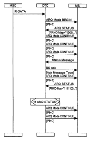
FIG. 4 illustrates how an ARQ Mode transaction, terminated in a receiving
entity,
can be interrupted by a Status Message. In FIG. 4, the transmitting entity is
depicted as a
base station (BS), and the receiving entity is depicted as a mobile station
(MS). It should
appreciated that the transmitting entity and the receiving entity may be other
devices. For
example, the transmitting entity may be a BSC, an MSC, or an MS, and the
receiving
entity may be a BS, a BSC, or an MSC. As shown in FIG. 4, an MSC transmits an
R-DATA message to the BS over a DTC to a particular MS. In the example shown
in
FIG. 4, the R-DATA is sent while the BS and the MS are already in a
conversation state.
The R-DATA may be sent at any time, after initial connection.
The BS begins an ARQ Mode transaction by transmitting an ARQ Mode BEGIN
frame to the MS. The PI is set to 1, indicating a request for the MS to send
an ARQ
STATUS frame. The MS responds with an ARQ STATUS frame with the FRNO MAP
set to 1000 . . . indicating that the MS has received the first frame
successfully. An ARQ
Mode CONTINUE frame is sent to the MS. The PI is then set to 0, and ARQ Mode
CONTINUE frames are repeatedly sent to the MS. After a few more ARQ Mode
CONTINUE frames are sent, the MS~sends a Status Message. The BS responds with
a
BS Acknowledgement (Ack) message, interrupting the ARQ Mode transaction. The
ARQ transaction is resumed by the BS transmitting the next ARQ Mode CONTINUE
frame, with the PI equal to one. If the MS responds to the PI by transmitting
an ARQ
CA 02351422 2001-05-18
WO 00/31928 PCT/SE99/02099 -
-12-
STATUS frame, the BS will know that the MS is in a mode to handle the rest of
the
transaction. Otherwise, if no ARQ STATUS message is received by the BS, the BS
may
repeat the ARQ Mode CONTINUE frame. Eventually, if no ARQ STATUS message is
received by the BS, the ARQ Mode transaction is aborted.
If the BS receives the ARQ STATUS frame, with the FRNO map set to, for
example, 1111100 . . . indicating that the first five frames have been
successfully received
by the MS, the process continues as long as the both the MS and the BS are in
the ARQ
Mode. Of course, the FRNO map may be set to 1---100 . . . where ' =" may be a
1 or a 0,
since any of the frames between the ARQ BEGIN frame and the last frame with PI
= 1
may or may not have been received.
Although not illustrated, it will be appreciated that the ARQ Mode transaction
may be interrupted by other messages from the MS, e.g., a CQM reports, or the
interruption can be initiated by the MSC or BS, e.g., to perform handoff of
the MS.
According to exemplary embodiments, a technique is provided for resuming re-
transmission after interruption, without requiring that the re-transmission
process be
started over. This results in a savings of bandwidth. Also, existing messages
provided
for in the receiving and transmitting entities may be used.
It will be appreciated by those of ordinary skill in the art that this
invention can be
embodied in other specific forms without departing from its essential
character. The
embodiments described above should therefore be considered in all respects to
be
illustrative and not restrictive. For example, although the embodiments
described above
are directed to an IS-136 environment, the invention is not limited to a
system complying
with this standard.