Language selection

Search

Patent 2351459 Summary

Third-party information liability

Some of the information on this Web page has been provided by external sources. The Government of Canada is not responsible for the accuracy, reliability or currency of the information supplied by external sources. Users wishing to rely upon this information should consult directly with the source of the information. Content provided by external sources is not subject to official languages, privacy and accessibility requirements.

Claims and Abstract availability

Any discrepancies in the text and image of the Claims and Abstract are due to differing posting times. Text of the Claims and Abstract are posted:

  • At the time the application is open to public inspection;
  • At the time of issue of the patent (grant).
(12) Patent: (11) CA 2351459
(54) English Title: KEYED ANTI-WEAR THRUST WASHER STRUCTURE
(54) French Title: RONDELLE DE BUTEE ANTI-USURE CLAVETEE
Status: Expired and beyond the Period of Reversal
Bibliographic Data
(51) International Patent Classification (IPC):
  • F16B 43/00 (2006.01)
  • F16D 1/08 (2006.01)
(72) Inventors :
  • SWARTZENDRUBER, JAMES ALLEN (United States of America)
  • HUTCHISON, WAYNE ROBERT (United States of America)
(73) Owners :
  • DEERE & COMPANY
(71) Applicants :
  • DEERE & COMPANY (United States of America)
(74) Agent: BORDEN LADNER GERVAIS LLP
(74) Associate agent:
(45) Issued: 2004-10-19
(22) Filed Date: 2001-06-22
(41) Open to Public Inspection: 2002-02-09
Examination requested: 2001-06-22
Availability of licence: N/A
Dedicated to the Public: N/A
(25) Language of filing: English

Patent Cooperation Treaty (PCT): No

(30) Application Priority Data:
Application No. Country/Territory Date
09/634,189 (United States of America) 2000-08-09

Abstracts

English Abstract


A thrust washer structure includes a non-rotating washer which bears against
the
transmission housing. A rotating outer washer is positioned over the axle and
includes a tab
projecting at a right angle from a portion of the washer face such that the
tab engages an
existing keyway in the wheel hub or bushing utilized to transmit drive from
the axle to the
drive wheel.


Claims

Note: Claims are shown in the official language in which they were submitted.

CLAIMS
The embodiments of the invention in which an exclusive property or privilege
is
claimed are defined as follows:
1. In a drive for a driven vehicle including a transmission having a
transmission
housing, a drive axle projecting from the housing, drive wheel structure
supported on the
drive axle, and a keyway extending between the drive wheel structure and the
drive axle, a
key supported in the keyway and transmitting drive from the drive axle to the
drive wheel
structure, thrust washer structure preventing wear of the transmission housing
as the drive
wheel structure is urged axially towards the transmission housing as the
vehicle is driven,
the thrust washer structure comprising: a fixed washer supported by the
transmission, a
generally flat washer slidably received over the drive axle for rotation
against the fixed
washer and including a tab projecting from the flat washer at generally a
right angle to the
flat washer, and wherein the tab is received in the keyway to constrain the
flat washer for
rotation with the drive wheel structure without need for additional notched
structure to
receive the tab.
2. The thrust washer structure as set forth in claim 1 wherein the keyway
includes a
groove portion extending to one end of the drive wheel structure and wherein
the tab is
received within the groove portion at the one end.
3. The thrust washer structure as set forth in claim 2 wherein the groove
portion is
located in the drive wheel structure.
4. A thrust washer for a drive shaft projecting from a transmission housing,
the drive
shaft receiving drive wheel hub structure and including keyway structure
located between
the drive shaft and the hub structure, the thrust washer comprising a planar
annular portion
with a central opening conforming to the drive shaft for receipt thereon
adjacent the
transmission housing, and a tab projecting at generally a right angle to the
plane of the
annual portion at the central opening for receipt by the keyway structure to
constrain the
annular portion for rotation in unison with the drive shaft.
5. The thrust washer as set forth in claim 4 wherein the central opening has a
generally circular periphery and the tab projects from the periphery.
6. The thrust washer as set forth in claim 5 further including notches
projecting
radially from the periphery on opposite sides of the tab.
7. The thrust washer as set forth in claim 5 wherein the tab has a thickness
no

greater than keyway structure depth so that substantially all the tab is
received in the
keyway when positioned on the drive shaft.
8. The thrust washer as set forth in claim 5 wherein the annular portion
includes first
and second planar faces, and wherein the tab includes a bend location located
substantially
entirely between the planar faces.

Description

Note: Descriptions are shown in the official language in which they were submitted.


CA 02351459 2001-06-22
KEYED ANTI-WEAR THRUST WASHER STRUCTURE
BACKGROUND OF THE INVENTION
7) Field of the Invention:
The present invention relates generally to drives for vehicles such as lawn
and
garden tractors and, more specifically, to thrust washers for axle shafts of
such vehicles.
2) Related Art:
Lawn and garden tractors typically include drive wheels mounted on keyed axle
shafts. The drive wheels or wheel hubs are often free floating on the keyed
axle shafts and
deliver thrust against the transmission housing in the area around the shafts.
A non-rotating
washer which engages the transmission housing is placed between the end of the
housing
and the wheel or wheel hub to protect the axle seal. However, after continued
use the
washer can wear through and no longer protect the seal. Once the washer is
worn through
and seal damage occurs, transmission fluid can be lost, resulting in costly
transmission
failure. One solution to the thrust washer wear problem is to place a second
washer on the
shaft which rotates with the shaft and bears against the non-rotating washer.
Using the two
washer approach results in significantly increased washer life. However,
keying the second
washer to the rotating shaft has proven to be costly because the wheel hubs or
wheel
bushings have to be machined to provide a mating notch for a tab which
projects from the
plane of the rotating washer at an angle of about 45 degrees.
BRIEF DESCRIPTION OF THE INVENTION
It is therefore an object of the invention to provide an improved thrust
washer
structure for the drive of a vehicle such as a lawn and garden tractor. It is
another object of
the invention to provide such a structure which overcomes the aforementioned
problems.
It is a further object of the invention to provide an improved thrust washer
structure
for a vehicle drive which includes a fixed washer and a second washer keyed to
rotate with
the drive axle. It is another object to provide such a structure which has a
significantly
increased wear life compared to a single washer thrust arrangement but which
is relatively
inexpensive. It is still another object to provide such a structure which
obviates a machining
step by eliminating the notch for the projecting tab of the rotating washer.
A thrust washer structure constructed in accordance with the teachings of the
present invention includes a first non-rotating washer which bears against the
transmission
housing. A rotating outer washer is positioned over the axle and includes a
tab projecting at
a right angle from a portion of the washer face such that the tab engages an
existing
keyway utilized to transmit drive from the axle to the drive wheel. In the
embodiment
shown, the tab seats in a keyway located in the wheel hub or bushing.

CA 02351459 2001-06-22
The thrust washer structure requires no machined notches and instead utilizes
an
existing keyway, thereby saving manufacturing time and expense. Since an
existing keyway
is utilized, the rotating keyed washer can be retrofitted to existing products
therefore
substantially increasing the cost savings. The tab is substantially contained
within the
keyway to provide a compact arrangement, and the area adjacent the keyway
remains
relatively unencumbered by additional structure.
These and other objects, features and advantages of the present invention will
become apparent to one skilled in the art upon reading the following detailed
description in
view of the drawings.
BRIEF DESCRIPTION OF THE DRAWINGS
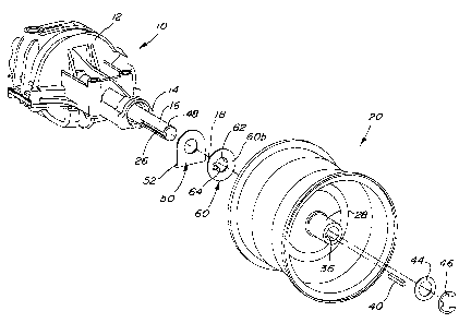
FIG. 1 is an exploded view of a portion of a transmission and drive wheel
structure
showing the thrust washer arrangement of the present invention.
FIG. 2 is a perspective view of a portion of the hub area of the wheel
structure of
FIG. 1 partially cut away to more clearly show the keyway.
FIG. 3 is an enlarged end view of the thrust washer of the arrangement of FIG.
1.
FIG. 4 is a front view of the washer of FIG. 3.
DETAILED DESCRIPTION OF THE DRAWINGS
Referring now to FIG. 1, therein is shown a portion of a transmission or
transaxle 10
for a lawn and garden tractor or similar vehicle. The transaxle 10 includes a
housing 12 with
a housing end area 14. A drive shaft or axle 16 projects outwardly from the
housing end
area 14 for rotation about a transversely extending axis 18. Drive wheel
structure 20 is
keyed to the shaft 16 for rotation with the shaft about the axis 18. Seal
structure (not
shown) in the end area 14 seals between the shaft 16 and the housing to
prevent
transmission fluid from leaking from the transaxle 10.
The shaft 16 includes an axially extending groove or keyway 26, and the wheel
structure 20 includes a hub 28 with a corresponding groove or keyway 36 which
aligns with
the keyway 26 when the drive wheel structure is mounted on the shaft 16. A key
40 having
a rectangular cross section conforming to the keyways 26 and 36 is positioned
in the
keyways to constrain the wheel structure 20 for rotation with the shaft 16.
The structure 20
can freely float axially on the shaft 16 in such a way that thrust is
delivered against the
housing end area 14 of the transaxle housing 12 by the inside end of the hub
28. A washer
44, along with a snap ring 46 which fits in a circumferential groove 48 at the
end of the shaft
2 __

CA 02351459 2001-06-22
16, maintain the wheel structure on the shaft 16.
To prevent the inside end of the hub 28 from wearing into the housing end area
14
and damaging the seals, a fixed L-shaped washer 50 is positioned over the
shaft 16 against
the housing 12. The washer 50 includes a lower projection 52 which fits
against the housing
12 to prevent rotation of the washer 50. To prevent the washer 50 from
prematurely
wearing through, a second washer 60 is positioned over the shaft 16 against
the outer face
of the washer 50 and is constrained to rotate with the wheel hub 28. The
thrust forces are
therefore spread over a greater area so that wear is reduced and both washers
50 and 60
have increased life.
The washer 60 includes opposite inner and outer planer faces 60a and 60b and a
central circular opening 62 of diameter slightly larger than the diameter of
the shaft 16. A
tab 64 projects outwardly from the washer 60 at an angle of 90 degrees from
the washer
face at the periphery of the opening 62 with the bottom of the tab 64a lying
generally on the
periphery. As shown (FIG. 2) the tab 64 engages inner end 36a of the existing
keyway 36
and is substantially contained within the keyway. The tab 64 constrains the
washer 60 to
rotate with the wheel hub 28 without need for a separate groove machined in
the inside end
of the hub 28. Rounded notches 68 project radially outwardly from the opening
62 adjacent
the sides of the tab 64 to facilitate the outward bending of the tab while
maintaining a strong
bend location that will resist fracturing during operation. The structure
assures that the
washer 60 can be fabricated with a strong tab connecting area without
projecting the bend
location (see 64b of FIG. 3) outside the planes of the opposite faces of the
washer 60,
thereby obviating any need for an additional groove in the hub 28.
In operation, the face of the hub 28 adjacent the keyway end 36a abuts the
face 60a
of the washer 60. The washer tab 64 is received within the keyway end 36a so
the washer
60 rotates with the wheel structure 20 as the transaxle 10 drives the shaft
16. The inner
face 60a of the washer 60 rotates against the outer face of the fixed washer
50 to spread
the thrust forces over a relatively large area so that wear is reduced.
Having described the preferred embodiment, it will become apparent that
various
modifications can be made without departing from the scope of the invention as
defined in
the accompanying claims.
3

Representative Drawing
A single figure which represents the drawing illustrating the invention.
Administrative Status

2024-08-01:As part of the Next Generation Patents (NGP) transition, the Canadian Patents Database (CPD) now contains a more detailed Event History, which replicates the Event Log of our new back-office solution.

Please note that "Inactive:" events refers to events no longer in use in our new back-office solution.

For a clearer understanding of the status of the application/patent presented on this page, the site Disclaimer , as well as the definitions for Patent , Event History , Maintenance Fee  and Payment History  should be consulted.

Event History

Description Date
Time Limit for Reversal Expired 2007-06-22
Inactive: Adhoc Request Documented 2006-08-11
Amendment Received - Voluntary Amendment 2006-08-11
Letter Sent 2006-06-22
Inactive: IPC from MCD 2006-03-12
Grant by Issuance 2004-10-19
Inactive: Cover page published 2004-10-18
Pre-grant 2004-07-22
Inactive: Final fee received 2004-07-22
Notice of Allowance is Issued 2004-02-11
Letter Sent 2004-02-11
Inactive: Approved for allowance (AFA) 2004-01-22
Application Published (Open to Public Inspection) 2002-02-09
Inactive: Cover page published 2002-02-08
Inactive: First IPC assigned 2001-08-27
Inactive: Filing certificate - RFE (English) 2001-07-23
Filing Requirements Determined Compliant 2001-07-23
Letter Sent 2001-07-23
Application Received - Regular National 2001-07-23
All Requirements for Examination Determined Compliant 2001-06-22
Request for Examination Requirements Determined Compliant 2001-06-22

Abandonment History

There is no abandonment history.

Maintenance Fee

The last payment was received on 2004-06-03

Note : If the full payment has not been received on or before the date indicated, a further fee may be required which may be one of the following

  • the reinstatement fee;
  • the late payment fee; or
  • additional fee to reverse deemed expiry.

Please refer to the CIPO Patent Fees web page to see all current fee amounts.

Fee History

Fee Type Anniversary Year Due Date Paid Date
Application fee - standard 2001-06-22
Request for examination - standard 2001-06-22
Registration of a document 2001-06-22
MF (application, 2nd anniv.) - standard 02 2003-06-23 2003-06-20
MF (application, 3rd anniv.) - standard 03 2004-06-22 2004-06-03
Final fee - standard 2004-07-22
MF (patent, 4th anniv.) - standard 2005-06-22 2005-06-03
Owners on Record

Note: Records showing the ownership history in alphabetical order.

Current Owners on Record
DEERE & COMPANY
Past Owners on Record
JAMES ALLEN SWARTZENDRUBER
WAYNE ROBERT HUTCHISON
Past Owners that do not appear in the "Owners on Record" listing will appear in other documentation within the application.
Documents

To view selected files, please enter reCAPTCHA code :


To view images, click a link in the Document Description column. To download the documents, select one or more checkboxes in the first column and then click the "Download Selected in PDF format (Zip Archive)" or the "Download Selected as Single PDF" button.

List of published and non-published patent-specific documents on the CPD .

If you have any difficulty accessing content, you can call the Client Service Centre at 1-866-997-1936 or send them an e-mail at CIPO Client Service Centre.


Document
Description 
Date
(yyyy-mm-dd) 
Number of pages   Size of Image (KB) 
Representative drawing 2002-01-14 1 14
Cover Page 2002-02-01 1 38
Description 2001-06-22 3 178
Abstract 2001-06-22 1 12
Drawings 2001-06-22 2 52
Claims 2001-06-22 2 65
Cover Page 2004-09-22 1 39
Courtesy - Certificate of registration (related document(s)) 2001-07-23 1 112
Filing Certificate (English) 2001-07-23 1 163
Reminder of maintenance fee due 2003-02-25 1 107
Commissioner's Notice - Application Found Allowable 2004-02-11 1 161
Maintenance Fee Notice 2006-08-17 1 173
Correspondence 2004-07-22 1 25