Sélection de la langue

Search

Sommaire du brevet 2351459 

Énoncé de désistement de responsabilité concernant l'information provenant de tiers

Une partie des informations de ce site Web a été fournie par des sources externes. Le gouvernement du Canada n'assume aucune responsabilité concernant la précision, l'actualité ou la fiabilité des informations fournies par les sources externes. Les utilisateurs qui désirent employer cette information devraient consulter directement la source des informations. Le contenu fourni par les sources externes n'est pas assujetti aux exigences sur les langues officielles, la protection des renseignements personnels et l'accessibilité.

Disponibilité de l'Abrégé et des Revendications

L'apparition de différences dans le texte et l'image des Revendications et de l'Abrégé dépend du moment auquel le document est publié. Les textes des Revendications et de l'Abrégé sont affichés :

  • lorsque la demande peut être examinée par le public;
  • lorsque le brevet est émis (délivrance).
(12) Brevet: (11) CA 2351459
(54) Titre français: RONDELLE DE BUTEE ANTI-USURE CLAVETEE
(54) Titre anglais: KEYED ANTI-WEAR THRUST WASHER STRUCTURE
Statut: Périmé et au-delà du délai pour l’annulation
Données bibliographiques
(51) Classification internationale des brevets (CIB):
  • F16B 43/00 (2006.01)
  • F16D 1/08 (2006.01)
(72) Inventeurs :
  • SWARTZENDRUBER, JAMES ALLEN (Etats-Unis d'Amérique)
  • HUTCHISON, WAYNE ROBERT (Etats-Unis d'Amérique)
(73) Titulaires :
  • DEERE & COMPANY
(71) Demandeurs :
  • DEERE & COMPANY (Etats-Unis d'Amérique)
(74) Agent: BORDEN LADNER GERVAIS LLP
(74) Co-agent:
(45) Délivré: 2004-10-19
(22) Date de dépôt: 2001-06-22
(41) Mise à la disponibilité du public: 2002-02-09
Requête d'examen: 2001-06-22
Licence disponible: S.O.
Cédé au domaine public: S.O.
(25) Langue des documents déposés: Anglais

Traité de coopération en matière de brevets (PCT): Non

(30) Données de priorité de la demande:
Numéro de la demande Pays / territoire Date
09/634,189 (Etats-Unis d'Amérique) 2000-08-09

Abrégés

Abrégé anglais


A thrust washer structure includes a non-rotating washer which bears against
the
transmission housing. A rotating outer washer is positioned over the axle and
includes a tab
projecting at a right angle from a portion of the washer face such that the
tab engages an
existing keyway in the wheel hub or bushing utilized to transmit drive from
the axle to the
drive wheel.

Revendications

Note : Les revendications sont présentées dans la langue officielle dans laquelle elles ont été soumises.


CLAIMS
The embodiments of the invention in which an exclusive property or privilege
is
claimed are defined as follows:
1. In a drive for a driven vehicle including a transmission having a
transmission
housing, a drive axle projecting from the housing, drive wheel structure
supported on the
drive axle, and a keyway extending between the drive wheel structure and the
drive axle, a
key supported in the keyway and transmitting drive from the drive axle to the
drive wheel
structure, thrust washer structure preventing wear of the transmission housing
as the drive
wheel structure is urged axially towards the transmission housing as the
vehicle is driven,
the thrust washer structure comprising: a fixed washer supported by the
transmission, a
generally flat washer slidably received over the drive axle for rotation
against the fixed
washer and including a tab projecting from the flat washer at generally a
right angle to the
flat washer, and wherein the tab is received in the keyway to constrain the
flat washer for
rotation with the drive wheel structure without need for additional notched
structure to
receive the tab.
2. The thrust washer structure as set forth in claim 1 wherein the keyway
includes a
groove portion extending to one end of the drive wheel structure and wherein
the tab is
received within the groove portion at the one end.
3. The thrust washer structure as set forth in claim 2 wherein the groove
portion is
located in the drive wheel structure.
4. A thrust washer for a drive shaft projecting from a transmission housing,
the drive
shaft receiving drive wheel hub structure and including keyway structure
located between
the drive shaft and the hub structure, the thrust washer comprising a planar
annular portion
with a central opening conforming to the drive shaft for receipt thereon
adjacent the
transmission housing, and a tab projecting at generally a right angle to the
plane of the
annual portion at the central opening for receipt by the keyway structure to
constrain the
annular portion for rotation in unison with the drive shaft.
5. The thrust washer as set forth in claim 4 wherein the central opening has a
generally circular periphery and the tab projects from the periphery.
6. The thrust washer as set forth in claim 5 further including notches
projecting
radially from the periphery on opposite sides of the tab.
7. The thrust washer as set forth in claim 5 wherein the tab has a thickness
no

greater than keyway structure depth so that substantially all the tab is
received in the
keyway when positioned on the drive shaft.
8. The thrust washer as set forth in claim 5 wherein the annular portion
includes first
and second planar faces, and wherein the tab includes a bend location located
substantially
entirely between the planar faces.

Description

Note : Les descriptions sont présentées dans la langue officielle dans laquelle elles ont été soumises.

CA 02351459 2001-06-22
KEYED ANTI-WEAR THRUST WASHER STRUCTURE
BACKGROUND OF THE INVENTION
7) Field of the Invention:
The present invention relates generally to drives for vehicles such as lawn
and
garden tractors and, more specifically, to thrust washers for axle shafts of
such vehicles.
2) Related Art:
Lawn and garden tractors typically include drive wheels mounted on keyed axle
shafts. The drive wheels or wheel hubs are often free floating on the keyed
axle shafts and
deliver thrust against the transmission housing in the area around the shafts.
A non-rotating
washer which engages the transmission housing is placed between the end of the
housing
and the wheel or wheel hub to protect the axle seal. However, after continued
use the
washer can wear through and no longer protect the seal. Once the washer is
worn through
and seal damage occurs, transmission fluid can be lost, resulting in costly
transmission
failure. One solution to the thrust washer wear problem is to place a second
washer on the
shaft which rotates with the shaft and bears against the non-rotating washer.
Using the two
washer approach results in significantly increased washer life. However,
keying the second
washer to the rotating shaft has proven to be costly because the wheel hubs or
wheel
bushings have to be machined to provide a mating notch for a tab which
projects from the
plane of the rotating washer at an angle of about 45 degrees.
BRIEF DESCRIPTION OF THE INVENTION
It is therefore an object of the invention to provide an improved thrust
washer
structure for the drive of a vehicle such as a lawn and garden tractor. It is
another object of
the invention to provide such a structure which overcomes the aforementioned
problems.
It is a further object of the invention to provide an improved thrust washer
structure
for a vehicle drive which includes a fixed washer and a second washer keyed to
rotate with
the drive axle. It is another object to provide such a structure which has a
significantly
increased wear life compared to a single washer thrust arrangement but which
is relatively
inexpensive. It is still another object to provide such a structure which
obviates a machining
step by eliminating the notch for the projecting tab of the rotating washer.
A thrust washer structure constructed in accordance with the teachings of the
present invention includes a first non-rotating washer which bears against the
transmission
housing. A rotating outer washer is positioned over the axle and includes a
tab projecting at
a right angle from a portion of the washer face such that the tab engages an
existing
keyway utilized to transmit drive from the axle to the drive wheel. In the
embodiment
shown, the tab seats in a keyway located in the wheel hub or bushing.

CA 02351459 2001-06-22
The thrust washer structure requires no machined notches and instead utilizes
an
existing keyway, thereby saving manufacturing time and expense. Since an
existing keyway
is utilized, the rotating keyed washer can be retrofitted to existing products
therefore
substantially increasing the cost savings. The tab is substantially contained
within the
keyway to provide a compact arrangement, and the area adjacent the keyway
remains
relatively unencumbered by additional structure.
These and other objects, features and advantages of the present invention will
become apparent to one skilled in the art upon reading the following detailed
description in
view of the drawings.
BRIEF DESCRIPTION OF THE DRAWINGS
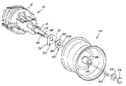
FIG. 1 is an exploded view of a portion of a transmission and drive wheel
structure
showing the thrust washer arrangement of the present invention.
FIG. 2 is a perspective view of a portion of the hub area of the wheel
structure of
FIG. 1 partially cut away to more clearly show the keyway.
FIG. 3 is an enlarged end view of the thrust washer of the arrangement of FIG.
1.
FIG. 4 is a front view of the washer of FIG. 3.
DETAILED DESCRIPTION OF THE DRAWINGS
Referring now to FIG. 1, therein is shown a portion of a transmission or
transaxle 10
for a lawn and garden tractor or similar vehicle. The transaxle 10 includes a
housing 12 with
a housing end area 14. A drive shaft or axle 16 projects outwardly from the
housing end
area 14 for rotation about a transversely extending axis 18. Drive wheel
structure 20 is
keyed to the shaft 16 for rotation with the shaft about the axis 18. Seal
structure (not
shown) in the end area 14 seals between the shaft 16 and the housing to
prevent
transmission fluid from leaking from the transaxle 10.
The shaft 16 includes an axially extending groove or keyway 26, and the wheel
structure 20 includes a hub 28 with a corresponding groove or keyway 36 which
aligns with
the keyway 26 when the drive wheel structure is mounted on the shaft 16. A key
40 having
a rectangular cross section conforming to the keyways 26 and 36 is positioned
in the
keyways to constrain the wheel structure 20 for rotation with the shaft 16.
The structure 20
can freely float axially on the shaft 16 in such a way that thrust is
delivered against the
housing end area 14 of the transaxle housing 12 by the inside end of the hub
28. A washer
44, along with a snap ring 46 which fits in a circumferential groove 48 at the
end of the shaft
2 __

CA 02351459 2001-06-22
16, maintain the wheel structure on the shaft 16.
To prevent the inside end of the hub 28 from wearing into the housing end area
14
and damaging the seals, a fixed L-shaped washer 50 is positioned over the
shaft 16 against
the housing 12. The washer 50 includes a lower projection 52 which fits
against the housing
12 to prevent rotation of the washer 50. To prevent the washer 50 from
prematurely
wearing through, a second washer 60 is positioned over the shaft 16 against
the outer face
of the washer 50 and is constrained to rotate with the wheel hub 28. The
thrust forces are
therefore spread over a greater area so that wear is reduced and both washers
50 and 60
have increased life.
The washer 60 includes opposite inner and outer planer faces 60a and 60b and a
central circular opening 62 of diameter slightly larger than the diameter of
the shaft 16. A
tab 64 projects outwardly from the washer 60 at an angle of 90 degrees from
the washer
face at the periphery of the opening 62 with the bottom of the tab 64a lying
generally on the
periphery. As shown (FIG. 2) the tab 64 engages inner end 36a of the existing
keyway 36
and is substantially contained within the keyway. The tab 64 constrains the
washer 60 to
rotate with the wheel hub 28 without need for a separate groove machined in
the inside end
of the hub 28. Rounded notches 68 project radially outwardly from the opening
62 adjacent
the sides of the tab 64 to facilitate the outward bending of the tab while
maintaining a strong
bend location that will resist fracturing during operation. The structure
assures that the
washer 60 can be fabricated with a strong tab connecting area without
projecting the bend
location (see 64b of FIG. 3) outside the planes of the opposite faces of the
washer 60,
thereby obviating any need for an additional groove in the hub 28.
In operation, the face of the hub 28 adjacent the keyway end 36a abuts the
face 60a
of the washer 60. The washer tab 64 is received within the keyway end 36a so
the washer
60 rotates with the wheel structure 20 as the transaxle 10 drives the shaft
16. The inner
face 60a of the washer 60 rotates against the outer face of the fixed washer
50 to spread
the thrust forces over a relatively large area so that wear is reduced.
Having described the preferred embodiment, it will become apparent that
various
modifications can be made without departing from the scope of the invention as
defined in
the accompanying claims.
3

Dessin représentatif
Une figure unique qui représente un dessin illustrant l'invention.
États administratifs

2024-08-01 : Dans le cadre de la transition vers les Brevets de nouvelle génération (BNG), la base de données sur les brevets canadiens (BDBC) contient désormais un Historique d'événement plus détaillé, qui reproduit le Journal des événements de notre nouvelle solution interne.

Veuillez noter que les événements débutant par « Inactive : » se réfèrent à des événements qui ne sont plus utilisés dans notre nouvelle solution interne.

Pour une meilleure compréhension de l'état de la demande ou brevet qui figure sur cette page, la rubrique Mise en garde , et les descriptions de Brevet , Historique d'événement , Taxes périodiques et Historique des paiements devraient être consultées.

Historique d'événement

Description Date
Le délai pour l'annulation est expiré 2007-06-22
Inactive : Demande ad hoc documentée 2006-08-11
Modification reçue - modification volontaire 2006-08-11
Lettre envoyée 2006-06-22
Inactive : CIB de MCD 2006-03-12
Accordé par délivrance 2004-10-19
Inactive : Page couverture publiée 2004-10-18
Préoctroi 2004-07-22
Inactive : Taxe finale reçue 2004-07-22
Un avis d'acceptation est envoyé 2004-02-11
Lettre envoyée 2004-02-11
Inactive : Approuvée aux fins d'acceptation (AFA) 2004-01-22
Demande publiée (accessible au public) 2002-02-09
Inactive : Page couverture publiée 2002-02-08
Inactive : CIB en 1re position 2001-08-27
Inactive : Certificat de dépôt - RE (Anglais) 2001-07-23
Exigences de dépôt - jugé conforme 2001-07-23
Lettre envoyée 2001-07-23
Demande reçue - nationale ordinaire 2001-07-23
Toutes les exigences pour l'examen - jugée conforme 2001-06-22
Exigences pour une requête d'examen - jugée conforme 2001-06-22

Historique d'abandonnement

Il n'y a pas d'historique d'abandonnement

Taxes périodiques

Le dernier paiement a été reçu le 2004-06-03

Avis : Si le paiement en totalité n'a pas été reçu au plus tard à la date indiquée, une taxe supplémentaire peut être imposée, soit une des taxes suivantes :

  • taxe de rétablissement ;
  • taxe pour paiement en souffrance ; ou
  • taxe additionnelle pour le renversement d'une péremption réputée.

Veuillez vous référer à la page web des taxes sur les brevets de l'OPIC pour voir tous les montants actuels des taxes.

Historique des taxes

Type de taxes Anniversaire Échéance Date payée
Taxe pour le dépôt - générale 2001-06-22
Requête d'examen - générale 2001-06-22
Enregistrement d'un document 2001-06-22
TM (demande, 2e anniv.) - générale 02 2003-06-23 2003-06-20
TM (demande, 3e anniv.) - générale 03 2004-06-22 2004-06-03
Taxe finale - générale 2004-07-22
TM (brevet, 4e anniv.) - générale 2005-06-22 2005-06-03
Titulaires au dossier

Les titulaires actuels et antérieures au dossier sont affichés en ordre alphabétique.

Titulaires actuels au dossier
DEERE & COMPANY
Titulaires antérieures au dossier
JAMES ALLEN SWARTZENDRUBER
WAYNE ROBERT HUTCHISON
Les propriétaires antérieurs qui ne figurent pas dans la liste des « Propriétaires au dossier » apparaîtront dans d'autres documents au dossier.
Documents

Pour visionner les fichiers sélectionnés, entrer le code reCAPTCHA :


Pour visualiser une image, cliquer sur un lien dans la colonne description du document. Pour télécharger l'image (les images), cliquer l'une ou plusieurs cases à cocher dans la première colonne et ensuite cliquer sur le bouton "Télécharger sélection en format PDF (archive Zip)" ou le bouton "Télécharger sélection (en un fichier PDF fusionné)".

Liste des documents de brevet publiés et non publiés sur la BDBC .

Si vous avez des difficultés à accéder au contenu, veuillez communiquer avec le Centre de services à la clientèle au 1-866-997-1936, ou envoyer un courriel au Centre de service à la clientèle de l'OPIC.


Description du
Document 
Date
(aaaa-mm-jj) 
Nombre de pages   Taille de l'image (Ko) 
Dessin représentatif 2002-01-14 1 14
Page couverture 2002-02-01 1 38
Description 2001-06-22 3 178
Abrégé 2001-06-22 1 12
Dessins 2001-06-22 2 52
Revendications 2001-06-22 2 65
Page couverture 2004-09-22 1 39
Courtoisie - Certificat d'enregistrement (document(s) connexe(s)) 2001-07-23 1 112
Certificat de dépôt (anglais) 2001-07-23 1 163
Rappel de taxe de maintien due 2003-02-25 1 107
Avis du commissaire - Demande jugée acceptable 2004-02-11 1 161
Avis concernant la taxe de maintien 2006-08-17 1 173
Correspondance 2004-07-22 1 25