Note: Descriptions are shown in the official language in which they were submitted.
CA 02351542 2001-05-15
WO 00/28921 PCT/US99/26389
DESCRIPTION
Coiled-Sheet Stent-Graft With Exo-Skeleton
Field Of The Invention
The present invention relates generally to prostheses
for implantation with body lumens, and more particularly to
a stent-graft having a flexible exo-skeleton attached to a
tubular graft.
Background
Graft prostheses are often implanted within blood
vessels, particularly the aorta or other arteries, which may
be subject to aneurysm formation and/or severe athero-
sclerotic disease which may involve multiple stenoses. For
example, an aortic aneurysm may develop in a patient, for
example, within the abdominal aorta at the aorto-iliac
bifurcation, requiring treatment before the vessel wall
ruptures. To repair a blood vessel damaged by such an
affliction, a procedure involving use of a graft prosthesis
is generally performed.
A number of graft prostheses have been suggested that
include a tubular graft attached to a stent. The tubular
graft may be a biocompatible porous or nonporous tubular
structure to which a stent structure, such as a wire mesh,
may be attached. The stent structure may be biased to
assume an enlarged configuration corresponding to a target
treatment site, but may be constrained in a contracted
condition to facilitate introduction into a patient's vascu-
lature. The graft prosthesis may be percutaneously
introduced in the contracted condition, advanced to a
treatment site within a blood vessel, and released to assume
the enlarged condition and repair and/or bypass the
treatment site.
One problem often associated with such prostheses is
effectively securing the tubular graft at the treatment
site. The released graft prosthesis may not sufficiently
engage the vessel wall adjacent the treatment site, possibly
CA 02351542 2001-05-15
WO 00/28921 PCT/US99/Z6389
2
resulting in the graft prosthesis moving after implantation,
which may expose the damaged vessel wall. Plastically
deformable expandable stent structures may be provided to
attempt to more directly control the engagement between the
graft prosthesis and the vessel wall. Such expandable
structures, however, may require the use of a balloon or
other expandable member to expand the stmt structure to the
enlarged condition, which may introduce risks of uneven
stmt structure expansion and/or balloon rupture.
In addition to plastically deformable stents, coiled-
sheet stent structures have been suggested. Coiled-sheet
stems may provide enhanced anchoring within the blood
vessel because the size of the fully expanded stent may be
more precisely controlled. A coiled-sheet stent, however,
may be substantially rigid transverse to its longitudinal
axis, potentially resulting in a less flexible graft
prosthesis, which may not be implanted effectively in
tortuous anatomical conditions.
Therefore, there is a need for an improved stent-graft
that may provide improved flexibility, while still providing
substantial anchoring within a blood vessel.
Summary Of The Invention
The present invention is directed to a stmt-graft
having an exo-skeleton attached to a tubular graft. In
accordance with one aspect of the present invention, a
stent-graft is provided that includes a tubular graft having
a peripheral wall defining a periphery and a lumen therein,
the lumen extending axially between first and second ends of
the tubular graft. An exo-skeleton is attached to the
peripheral wall, the exo-skeleton including one or more
serpentine elements, each serpentine element extending both
peripherally, i.e., in a manner which generally surrounds
the wall which may be circular, elliptical or other suitable
configuration, and axially along at least a portion of the
peripheral wall. A stmt is provided on the first and/or
CA 02351542 2001-05-15
WO 00/28921 PCTNS99/26389
3
second ends for substantially anchoring the ends within a
body passage.
In a preferred form, each serpentine element is a
zigzag structure extending peripherally about the peripheral
wall of the tubular graft. More preferably, a plurality of
serpentine elements are distributed axially along the
peripheral wall for providing articulation of the tubular
graft between adjacent serpentine elements. The serpentine
elements may be individually attached to the peripheral wall
and/or the serpentine elements may be connected to one
another by one or more connector elements extending between
adjacent serpentine elements.
In another preferred form, each serpentine element
defines a generally sinusoidal shape extending axially along
the peripheral wall. Preferably, a plurality of serpentine
elements may distributed substantially evenly about the
periphery of the peripheral wall. Each of these serpentine
elements preferably includes substantially transverse peri-
pheral elements, adjacent transverse peripheral elements
being connected by alternating curved elements, thereby
defining the generally sinusoidal shape.
The exo-skeleton of the stent-graft is preferably
directable between a contracted condition for facilitating
introduction within a body passage and an enlarged condition
for deployment within the body passage. The exo-skeleton
may substantially support the tubular graft to hold the
lumen of the tubular graft substantially open in the
enlarged condition. In a preferred form, the exo-skeleton
is radially compressible to the contracted condition and
biased to assume the enlarged condition. Alternatively, the
contracted condition of the exo-skeleton may be achieved by
flattening and circumferentially rolling the exo-skeleton.
The tubular graft may be provided from a polymeric
material, such as polyester, polytetrafluorethaline, dacron,
teflon, and polyurethane. The exo-skeleton may be attached
to the tubular graft by sutures, staples, Wires, or an
adhesive, or alternatively by thermal bonding, chemical
CA 02351542 2001-05-15
WO 00/28921 PCT/US99/26389
4
bonding, and ultrasonic bonding. The exo-skeleton may be
formed from a metallic material, such as stainless steel or
Nitinol, and may be a flat-coiled sheet with the one or more
serpentine elements formed therein, or a wire formed into a
serpentine shape.
In alternative forms, the first and second ends of the
tubular graft may have similar cross-sections, or the first
end of the tubular graft may have a cross-section that is
substantially smaller than a cross-section of the second end
of the tubular graft. In addition, the exo-skeleton may be
attached to an exterior surface of the tubular graft, to an
interior surface of the tubular graft, or embedded in the
wall of the tubular graft.
In accordance with another aspect of the present
invention, a stmt-graft is provided for placement within a
bifurcation that includes a first tubular graft segment
having a first end and a second bifurcated end, the first
tubular graft segment having a first peripheral wall. A
second tubular graft segment extends from the second
bifurcated end, the second tubular graft segment having a
second peripheral wall. An exo-skeleton is attached to at
least one of the first and second peripheral walls, the exo-
skeleton including one or more serpentine elements, each
serpentine element extending both peripherally and axially
along at least a portion of the respective peripheral wall
to which it is attached.
A coiled-sheet stmt may be provided on the first end
for substantially anchoring the first end within a body
passage. Similarly, a coiled-sheet stent may be provided on
the second tubular graft segment opposite the second end of
the first tubular graft segment.
Preferably, the stent-graft also includes a third
tubular graft segment attachable to the second bifurcated
end, the third tubular graft segment having a third
peripheral wall. The exo-skeleton also may include one or
more serpentine elements attached to the third peripheral
wall.
CA 02351542 2001-05-15
WO 00/28921 PCT/US99/26389
Thus, a stmt-graft in accordance with the present
invention may have a substantially flexible region that may
conform substantially to the anatomy of a treatment site.
Preferably, the flexible region is defined by an exo-
5 skeleton attached to a tubular graft that includes one or
more serpentine elements. The serpentine elements may
facilitate articulation between adjacent serpentine
elements, and/or may be sufficiently resilient and flexible
to allow articulation, compression and/or expansion of the
serpentine elements themselves.
Preferably, the stent-graft also includes sealing
members, preferably coiled-sheet stents, attached to the
ends of the tubular graft for substantially sealing and/or
anchoring the ends of the tubular graft proximate the
treatment site. Thus, the stent-graft may accommodate
tortuous anatomy while still providing effective sealing and
anchoring within a body passage.
Other objects and features of the present invention
will become apparent from consideration of the following
description taken in conjunction with the accompanying
drawings.
Brief Description Of The Drawings
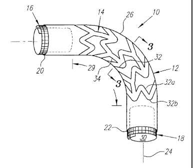
FIG. 1 shows a perspective view of a stent-graft with
exo-skeleton in accordance with the present invention.
FIG. 2 is a side view detail of the stent-graft of FIG.
1, showing a first preferred embodiment of a plurality of
serpentine elements defining the exo-skeleton.
FIGS. 3A and 3B are cross-sections of the stent-graft
of FIG. 1, taken along line 3-3, and showing the stent-graft
in contracted and enlarged conditions, respectively.
FIG. 4 is a perspective view of an alternative
embodiment of a serpentine element attachable to a tubular
graft (in phantomy.
FIGS. 5A-5D are end views of a stmt-graft in
accordance with the present invention, showing a method for
rolling the stmt-graft into a contracted condition.
CA 02351542 2001-05-15
WO 00/28921 PCT/US99/26389
6
FIG. 6 is a perspective view of another embodiment of a
stem -graft, having a tapered configuration.
FIG. 7 is a perspective view of still another
embodiment of a stent-graft, having a bifurcated main
segment, an extension segment and an attachable docking
limb.
FIG. 8 is a cross-sectional view of an abdomen, showing
a method for implanting a stmt-graft across a bifurcation
for treating an aneurysm at the bifurcation.
FIG. 9 is a side view of a fully stretchable stent for
use with a stent-graft in accordance with the present
invention.
FIGS. l0A and 10B are end and side views, respectively,
of a stent with anti-buckling segment.
FIGS. 11A and 11B are side and perspective views,
respectively, of a stent with stretchable ends.
Detailed Description Of The Preferred Embodiments
Turning now to the drawings, FIG. 1 shows a first
preferred embodiment of a stent-graft 10 in accordance with
the present invention that includes a tubular graft l2, an
exo-skeleton 14, and first and second coiled-sheet stents
16, 18. The tubular graft 12 has first and second ends 20,
22 defining a longitudinal axis 24 therebetween and a
peripheral wall 26 defining a periphery 28 and a lumen 30
therein. The tubular graft 12 may be formed from a variety
of biocompatible materials, preferably a polymeric material,
such as polyester, polytetrafluorethaline, dacron, teflon,
and polyurethane.
The exo-skeleton 19 is attached to the peripheral wall
26 and includes a plurality of serpentine elements 32. The
exo-skeleton 14 may be formed from a variety of semi-rigid
materials, preferably a biocompatible metallic material,
such as Nitinol or stainless steel. The material may be
resiliently deformable, may exhibit shape memory properties
and/or may be plastically deformable, as described further
below, to facilitate articulation of the stent-graft 10,
CA 02351542 2001-05-15
WO 00/28921 PCT/US99/26389
7
and/or the collapse and/or expansion of the exo-skeleton 14
between a contracted condition and an enlarged condition.
The exo-skeleton 14 may be formed from flat sheet material
having the individual serpentine elements 32 etched, cut or
otherwise formed from the sheet material. Alternatively,
the exo-skeleton 14 may be formed from wire-like materials,
for example, by forming each serpentine element 32 from a
single strand of wire.
The exo-skeleton 14 may be attached either to the
exterior of the peripheral wall 26, to the interior of the
peripheral wall 26, or alternatively embedded in the
peripheral wall 26, with the term "exo-skeleton" being
intended to include any of these locations and not to be
limited to one location over another. The exo-skeleton 14
may be attached by mechanical fasteners, such as sutures,
wires, staples, and the like, by an adhesive, or by a
bonding process, such as thermal bonding, chemical bonding,
or ultrasonic bonding.
Each serpentine element 32 extends both "peripherally"
and "axially" along at least a portion of the peripheral
wall 26. "Peripherally" refers to each serpentine element
32 extending in a manner which generally surrounds the
peripheral wall 26 which preferably may be circular or
elliptical, e.g., generally around the circumference or
other periphery of the peripheral wall 26, while "axially"
refers to the serpentine element 32 extending along the
peripheral wall 26 generally parallel to the longitudinal
axis 24. Thus, each serpentine element 32 defines a
generally "zigzag" shape made up, for example, of abrupt "Z"
and/or rounded "U" shaped elements integrally connected
together.
In a first preferred form, shown in FIGS. 1 and 2, the
serpentine elements 14 are defined by a plurality of zigzag
elements, including generally straight axial regions 32a and
curved peripheral regions 32b, integrally formed together
that extend substantially peripherally about the peripheral
wall 26. The serpentine elements 32 consequently provide a
CA 02351542 2001-05-15
WO 00/28921 PCT/US99/26389
8
multi-cellular exo-skeleton 14 that may facilitate
articulation between adjacent serpentine elements 32 when
the stmt-graft 10 is directed substantially transversely
with respect to the longitudinal axis 24.
In one form, the serpentine elements 32 are connected
by connector elements 34, which preferably extend
substantially axially between adjacent serpentine elements
32. The connector elements 34 may be formed, etched or cut,
when the serpentine elements are formed from a flat sheet,
or the connector elements 34 may be strands of wire attached
to the serpentine elements 32 in a conventional manner.
Alternatively, the serpentine elements 32 may be separate
structures that are individually attached to the peripheral
wall 26 of the tubular graft 12.
The coiled-sheet stems 16, 18 may be attached to the
respective ends 20, 22 of the tubular graft, preferably to
the interior of the peripheral wall 26, although
alternatively the coiled-sheet stents 16, 18 may be provided
as separate components from the tubular graft 12. The
coiled-sheet stents 16, 18 may expand automatically, but are
preferably mechanically expandable, e.g., they may be
ratchetable to larger diameters, for example, using a
balloon or other expandable member (not shown).
The coiled-sheet stents 16, 18 may have a stretchable
design, a stretchable anti-buckling segment, and/or a
stretchable crowning end. For example, as shown in FIG. 9,
a fully stretchable coiled-sheet stmt 410 is shown that is
formed from a substantially flat mesh structure 412 defining
individual resilient mesh elements 420 and having teeth 414
along a side edge 416 thereof for being received within the
mesh elements 420. The mesh structure 412 may be rolled or
coiled to define a longitudinal axis 418 and a circumference
or periphery (not shown) in a plane substantially
perpendicular to the longitudinal axis 418. The mesh
structure 412 may be formed from a plastically deformable
material, such as stainless steel.
CA 02351542 2001-05-15
WO 00/28921 PCT/US99/26389
9
In a preferred form, however, the mesh structure 412 is
formed from Nitinol or similar shape memory material, which
has, for example, been polished and/or heat treated. In a
free-stress state, e.g., the austenitic phase, the mesh
elements 420 preferably define a "stretched" condition,
i.e., expand about the periphery of the mesh structure 912
such that the mesh structure 912 is biased to assume an
enlarged size, e.g., substantially similar to the cross-
section of a vessel within which the stent 410 is to be
implanted. The mesh elements 420 may adopt an "unstretched"
configuration, i.e., may be compressed about the periphery
of the mesh structure 412, such that the mesh structure 412
adopts a substantially reduced size. This may be achieved
by transforming the Nitinol material of the mesh structure
412 to a martensitic phase, for example, upon cooling after
heat treatment. The stent 410 may then be rolled and/or
collapsed to a reduced delivery profile for attachment to a
stent-graft, such as those described herein.
When the stent 410 is implanted within a blood vessel,
the mesh structure 412 may stretch or return to its stress
free state, e.g., the austenitic phase, and expand to engage
the vessel wall. If radial pressure is applied to the stent
410 by the vessel, the mesh elements 420 may be compressed
about the periphery, thereby allowing the stent 410 to
recoil and substantially eliminate the likelihood of the
stmt 410 buckling, as may occur when a conventional coiled-
sheet stmt is subjected to substantial radially compressive
forces.
Turning to FIGS. 10A and lOB, another embodiment of a
coiled-sheet stent 510 is shown that has a stretchable anti
buckling segment 512 formed from a mesh structure that is
attached to a coiled-sheet portion 514. The coiled-sheet
portion 514 includes teeth 516 along a side edge 518 and may
be rolled or coiled to define overlapping inner and outer
longitudinal sections 524, 526, a longitudinal axis 520 and
a periphery 522 such that the anti-buckling segment 512
extends axially, i.e., substantially parallel to the
CA 02351542 2001-05-15
WO 00/28921 PCT/US99/26389
longitudinal axis 520. Similar to the previous embodiment,
the anti-buckling segment 512 may be formed from Nitinol,
which may be heat treated and stretched, and then cooled and
unstretched. The axially oriented anti-buckling segment 512
5 facilitates the entire stmt 510 recoiling when subjected to
radially compressive forces by providing mesh elements 529
which may be compressed about the periphery 522, as
described above. Thus, the stent 510 may combine the
benefits of both a coiled-sheet stmt, which is generally
10 incompressible about its periphery, and a stretchable stmt
structure.
Turning to FIGS. 11A and 11B, another embodiment of a
stent 610 is shown that includes an anti-buckling segment or
"crowning end" 616 on one end 614 of a coiled-sheet portion
612. The coiled-sheet portion 612 and anti-buckling segment
616 include teeth 618a, 618b along a side edge 620 thereof,
and may be rolled to define a longitudinal axis 622 and a
perimeter 624. The anti-buckling segment 616 is preferably
polished, heat treated into a desired shape, cooled and
unstretched, and then coiled to its collapsed and rolled
delivery profile. After being implanted, mesh elements 626
in the anti-buckling segment 616 may be compressed when the
stmt 610 is subjected to radially compressive forces,
similar to the embodiments described above, thereby allowing
the ends of the stent 610 to become tapered. Alternatively,
the end 628 of the anti-buckling segment 616 may be flared
outward (not shown) to thereby partially recoil under
radially compressive forces such that the stent adopts a
substantially uniform size upon implantation within a blood
vessel.
The coiled-sheet stents 16, 18 may also include
outwardly-oriented hooks or barbs (not shown) for enhancing
anchoring of the stent-graft 10 within a body passage. Pro-
thrombotic material (not shown) may be provided on the
exterior surfaces of the coiled-sheet stem s 16, 18, or
alternatively on the ends 20, 22 of the tubular graft 12, to
enhance sealing against the wall of the body passage.
CA 02351542 2001-05-15
WO 00/28921 PCT/US99/26389
11
Additional information on coiled sheet stents appropriate
for use with a stmt-graft in accordance with the present
invention may be found in U. S. Patent Nos. 4, 577, 631 issued
March 25, 1986 in the name of Kreamer, 5,007,926 issued
April 16, 1991 in the name of Derbyshire, 5,158,548 issued
October 28, 1992 in the name of Lau et al., Re 34,327
reissued July 27, 1993 in the name of Kreamer, 5,423,885
issued June 13, 1995 in the name of Williams, 5,441,515
issued August 15, 1995 in the name of Khosravi et al., and
5,443,500 issued August 22, 1995 in the name of Sigwart.
The disclosures of these references and any others cited
therein are expressly incorporated herein by reference.
Turning to FIGS. 3A and 3B, the stmt-graft 10 may be
radially compressible from an enlarged condition, shown in
FIG. 3B, to a contracted condition, shown in FIG. 3A. In a
preferred form, the exo-skeleton 19 may be resiliently
biased to assume the enlarged condition, but may be
constrained in the contracted condition to facilitate
introduction of the stmt-graft 10 into a patient's
vasculature.
For example, the stent-graft 10 may be constrained in
the contracted condition, and percutaneously introduced into
a blood vessel (not shown). The stmt-graft 10 may be
advanced to a target treatment site, e.g., within the aorta
or other blood vessel (not shown), and deployed, with the
exo-skeleton 14 automatically expanding to the enlarged
condition. The coiled-sheet stents 16, 18 may then be
expanded to a desired size to substantially engage and
anchor the ends 20, 22 of the tubular graft 12 in place
proximate the treatment site. Alternatively, if the coiled-
sheet stents 16, 18 are provided as separate components (not
shown), they may be subsequently deployed and expanded to
anchor the ends 20, 22 of the previously deployed tubular
graft 12.
The exo-skeleton 14 may be retained in the contracted
condition simply by applying a radial compressive force to
the stmt-graft 10 and constraining the stem-graft 10, for
CA 02351542 2001-05-15
WO 00/28921 PCT/US99/26389
12
example, within a sheath. Alternatively, if the exo-
skeleton 14 is formed from Nitinol, the martensitic
properties of the Nitinol may be used to substantially
retain the stent-graft 10 in the contracted condition after
being radially compressed. The "zigzag" configuration of
the serpentine elements 32 of the exo-skeleton 19 may
facilitate substantially uniform radial compression of the
stent-graft 10 when it is subjected to radially compressive
forces, as shown in FIG. 3A, thereby minimizing the risk of
localized stress in the exo-skeleton 14 and/or the tubular
graft 12.
When the exo-skeleton 14 automatically assumes the
enlarged condition, the serpentine elements 32 preferably
substantially expand and support the peripheral wall 26 of
the tubular graft 12, thereby maintaining the lumen 30
substantially open and unobstructed, as may be seen in FIG.
3B, for example, to facilitate blood flow through the
treatment site being repaired. In an alternative form, the
exo-skeleton 14 may be initially formed in the contracted
condition, but may be plastically deformable to the enlarged
condition, for example, using a balloon or other expandable
member after the stent-graft 10 has been deployed at the
treatment site, as will be appreciated by those skilled in
the art.
The multi-cellular configuration provided by the
plurality of serpentine elements 32 of the exo-skeleton 14
may facilitate the stent-graft 10 conforming substantially
to tortuous anatomy during advancement and/or, upon deploy-
ment at a treatment site. If the stent-graft 10 is
subjected to substantially transverse forces, for example,
when it is directed around a tightly curved region of a
blood vessel, the stmt-graft 10 may be easily articulated
between adjacent serpentine elements 32 ~to conform to the
shape of the blood vessel. In addition, the zigzag elements
of each serpentine element 32 may be resiliently deformable,
thereby further facilitating conformance with local anatomic
conditions. Thus, a stent-graft 10 in accordance with the
CA 02351542 2001-05-15
WO 00/28921 PCT/US99/26389
13
present invention may have a substantially flexible
intermediate region 29 extending between substantially rigid
anchoring stents 16, 18. The intermediate region 29 may
allow the tubular graft 12 to conform to the anatomy of the
treatment site, while the exo-skeleton 19 substantially
supports the tubular graft 12 to prevent collapse or
buckling.
Turning to FIG. 4, another preferred form of an exo
skeleton 114 is shown that includes one or more serpentine
elements 132 attached to the peripheral wall 126 of a
tubular graft 112 (in phantom) that extend substantially
axially along the longitudinal axis 124 of a stem -graft
110. Each serpentine element 132 preferably defines a
generally sinusoidal shape extending substantially axially
along the peripheral wall 126, and includes substantially
transverse peripheral elements 134, with adjacent peripheral
elements 134 being connected by alternating curved elements
136 to define the generally sinusoidal shape.
In a preferred form, a plurality of serpentine elements
132 may be provided distributed substantially evenly about
the periphery of the peripheral wall 126. For example, as
shown in FIGS. 5A-5D, a pair of serpentine elements 132 may
be attached to the peripheral wall 126 opposite one another.
Turning to FIGS. 5A-5D, a stent-graft 110 having a pair
of axial serpentine elements 132a, 132b is shown being
rolled from an enlarged condition to a contracted condition.
The exo-skeleton 114 is preferably biased to assume the
enlarged condition of FIG. 5A. Because of the spaces 133
extending substantially axially between the serpentine
elements.132a, 132b, the stent-graft 110, including coiled-
sheet stents (not shown) on the ends of the stent-graft 110,
may be flattened, as shown in FIG. 5B. One edge of the
stent-graft 110 may then be rolled, similar to a coiled-
sheet stent, as shown in FIG. 5C, until the entire stent-
graft 110 is fully rolled into the contracted condition,
shown in FIG. 5D, thereby providing a reduced profile. The
stent-graft 110 may then be retained in the contracted
CA 02351542 2001-05-15
WO 00/28921 PCT/US99/26389
14
condition to facilitate. introduction into and advancement
within a patient's vasculature, until deployed at a target
treatment site, whereupon the stmt-graft 110 may
automatically expand to its enlarged condition.
Turning to FIG. 6, another preferred embodiment of a
stent-graft 210 is shown, which has a substantially tapered
configuration between its first and second ends 220, 222.
Similar to the previous embodiments, the stmt-graft 210 has
a tubular graft 212 to which an exo-skeleton 214 is attached
to provide a resilient, flexible region. Coiled-sheet
stems 216, 218 are attached to the ends 220, 222 of the
tubular graft 212 for anchoring the ends 220, 222 within a
body passage. The second end 222 of the tubular graft 212
has a diameter that is substantially smaller than the first
end 220 to conform substantially to the anatomy of a tapered
blood vessel or to extend between a first larger vessel and
a second smaller vessel.
Turning to FIG. 8, a tapered stent-graft 210, such as
that just described, may be used in a method for repairing
an aortic aneurysm 250 that extends from an abdominal aorta
252 through a bifurcation 254 into the iliac arteries 256a,
256b. The stmt-graft 210, in a contracted condition, may
be introduced across the bifurcation 254 with the larger
first end 220 oriented towards the abdominal aorta 252. For
example, the stent-graft 210 may be placed on a catheter
delivery device (not shown), percutaneously introduced into
a peripheral artery (not shown), advanced into the
ipsilateral iliac artery 256a, and through the bifurcation
254 until the first end 220 reaches an undamaged region of
the abdominal aorta 252. The stmt-graft 210 may be then
deployed and expanded to its enlarged condition, for
example, when the exo-skeleton 214 automatically expands
upon deployment. Coiled-sheet stents 216, 218 on the stent-
graft 210 may be expanded to substantially seal and anchor
the stent-graft 210 to undamaged regions of the abdominal
aorta 252 and the ipsilateral iliac artery 256a,
respectively.
CA 02351542 2001-05-15
WO 00/28921 PCT/US99I26389
The contralateral iliac artery 256b may be
substantially permanently occluded with a vessel occluder
260, and a femoral-to-femoral bypass graft 270 may be
attached between the femoral arteries 258, or alternatively
5 between the iliac arteries 256, to allow blood flow from the
ipsilateral iliac artery 256a into the contralateral iliac
artery 256b and beyond.
Turning to FIG. 7, a stent-graft 310 for repairing a
bifurcation is shown, in accordance with another aspect of
10 the present invention. The stent-graft 310 includes a
plurality of tubular segments, namely a first main segment
312, a second extension segment 314 extending from the first
segment 312, and a third segment or "docking limb" 316 that
is attachable to a collar 318 on the first segment 312. The
15 first segment 312 has a first end 320 and a second
bifurcated end 32 defining a longitudinal axis 224
therebetween, with the second segment 314 and the collar 318
extending adjacent one another from the second bifurcated
end 322.
The first and second segments 312, 314 have first and
second peripheral walls 326, 328, respectively, which may be
integrally formed together, or may be provided as separate
wall portions that are attached to one another. The first
peripheral wall 326 defines a lumen 330 that extends from
the first end 320 through the first segment 312 and is
bifurcated into a first branch lumen 330a defined by the
second peripheral wall 328 and a second branch lumen 330b at
least partially defined by the collar 330b.
An exo-skeleton 332 is attached to at least one of the
first and second peripheral walls 326, 328 and/or the collar
318, which includes a plurality of serpentine elements 334,
similar to the serpentine elements previously described
herein. Preferably, a first set of serpentine elements 334a
are attached to the first peripheral wall 326 to support the
first segment 312, and a second set of serpentine elements
339b are attached to the second peripheral wall 328 to
support the second segment 319. The serpentine elements 339
CA 02351542 2001-05-15
WO 00/28921 PCT/US99/26389
16
may be individually attached to the respective peripheral
walls 326, 328 and/or adjacent serpentine elements may be
connected to one another by one or more connector elements
(not shown), as described above.
A first coiled-sheet stent 336 is attached to the first
end 320 for substantially anchoring and/or sealing the first
end 320 within a body passage. Similarly, a second coiled-
sheet stent 338 is attached to a distal end 340 of the
second segment 314.
The docking limb 316 has a third peripheral wall 348 to
which one or more serpentine elements 350 may be attached,
thereby further defining the exo-skeleton 332 of the stent-
graft 310. A third coiled-sheet stent 392 may be attached
to a first or distal end 344 of the docking limb 316. A
second or proximal end 346 of the docking limb 316 is
attachable to the collar 318 on the first segment 312, for
example, by a lap connection, or alternatively using another
coiled-sheet stent (not shown).
The exo-skeleton 332 may be directed between a
contracted condition for facilitating introduction within a
body passage and an enlarged condition for deployment within
the body passage, similar to the stmt-grafts previously
described herein. For example, each serpentine element
334a, 334b, 350 may be radially compressible to its
contracted condition and biased to assume its enlarged
condition.
In a preferred form, the first end 320 of the first
segment 312 has a size in its enlarged condition that
corresponds substantially to the diameter of an undamaged
region of an abdominal aorta. The distal ends 340, 344 of
the second segment 314 and the docking limb 316 have sizes
in their enlarged conditions that are substantially smaller
than the size of the first segment 312, preferably
corresponding substantially to the diameter of an undamaged
region of an iliac artery.
The first and second segments 312, 319 may be radially
compressed into their contracted conditions and directed
CA 02351542 2001-05-15
WO 00/28921 PCTNS99/26389
17
within a patient's vasculature to a bifurcated treatment
site, such as a site of an aneurysm at the aorto-iliac
bifurcation (not shown), similar to that shown in FIG. 8.
The first end 320 may be aligned with an undiseased region
of the abdominal aorta proximate the aneurysm, with the
second segment 314 extending into a first iliac artery and
the collar 318 oriented towards a second iliac artery. The
first and second segments 312, 314 may be deployed and
expanded to their enlarged conditions, and the first and
second coiled-sheet stems 336, 338 expanded to
substantially engage the walls of the undiseased abdominal
aorta and first iliac artery, respectively.
The docking limb 316, in its contracted condition, may
be advanced into the second iliac artery, and the proximal
end 346 aligned with the collar 318. The docking limb 316
may then be deployed and expanded to its enlarged condition
such that the proximal end 346 substantially engages the
collar 318. The third coiled-sheet stent 342 may be
expanded to substantially seal and engage an undiseased
region of the second iliac artery.
Thus, the damaged region of the aorto-iliac bifurcation
may be completely bypassed using a stent-graft 310 in
accordance with the present invention. The flexible exo-
skeleton 332 may allow the stent-graft 310 to conform
substantially to the anatomy at the bifurcated treatment
site, while supporting the tubular graft segments 312, 314,
316 to provide a substantially open and unobstructed lumen
to accommodate the flow of blood therethrough. The coiled-
sheet stents 336, 338, 342 may substantially anchor the
respective ends 320, 340, 344 of the stent-graft 310 and/or
substantially seal the stent-graft 310 to the walls of the
vessels.
While the invention is susceptible to various
modifications, and alternative forms, specific examples
thereof have been shown in the drawings and are herein
described in detail. It should be understood, however, that
the invention is not to be limited to the particular forms
CA 02351542 2001-05-15
WO 00/28921 PCT/US99/26389
18
or methods disclosed, but to the contrary, the invention is
to cover all modifications, equivalents and alternatives
falling within the spirit and scope of the appended claims.