Note: Descriptions are shown in the official language in which they were submitted.
CA 02351978 2001-06-28
r
DRILLING DIRECTION CONTROL DEVICE
FIELD OF INVENTION
The present invention relates to improvements in a drilling direction
control device.
BACKGROUND OF INVENTION
Directional drilling involves varying or controlling the direction of a
wellbore as it is being drilled. Usually the goal of directional drilling is
to reach or
maintain a position within a target subterranean destination or formation with
the
drilling string. For instance, the drilling direction may be controlled to
direct the
wellbore towards a desired target destination, to control the wellbore
horizontally to
maintain it within a desired payzone or to correct for unwanted or undesired
deviations
from a desired or predetermined path.
Thus, directional drilling may be defined as deflection of a wellbore along
a predetermined or desired path in order to reach or intersect with, or to
maintain a
position within, a specific subterranean formation or target. The
predetermined path
typically includes a depth where initial deflection occurs and a schedule of
desired
deviation angles and directions over the remainder of the wellbore. Thus,
deflection is
a change in the direction of the wellbore from the current wellbore path. This
deflection
may pertain to deviation of the wellbore path relative to vertical or to
change in the
horizontal direction or azimuth of the wellbore path.
It is often necessary to adjust the direction of the wellbore frequently while
directional drilling, either to accommodate a planned change in direction or
to
compensate for unintended or unwanted deflection of the wellbore. Unwanted
-1-
CA 02351978 2001-06-28
deflection may result from a variety of actors, including the characteristics
of the
formation being drilled, the makeup of the bottomhole drilling assembly and
the
manner in which the wellbore is being drilled.
Deflection is measured as an amount of deviation of the wellbore from the
current wellbore path and is expressed as a deviation angle or hole angle.
Deflection
may also relate to a change in the azimuth of the wellbore path. Commonly, the
initial
wellbore path is in a vertical direction. Thus, initial deflection often
signifies a point at
which the wellbore has deflected off vertical in a particular azimuthal
direction.
Deviation is commonly expressed as an angle in degrees from the vertical.
Azimuth is
commonly expressed as an angle in degrees relative to north.
Various techniques may be used for directional drilling. First, the drilling
bit may be rotated by a downhole motor which is powered by the circulation of
fluid
supplied from the surface. This technique, sometimes called "sliding
drilling", is
typically used in directional drilling to effect a change in direction of the
a wellbore,
such as the building of an angle of deflection. However, various problems are
often
encountered with sliding drilling.
For instance, sliding drilling typically involves the use of specialized
equipment in addition to the downhole drilling motor, including bent subs or
motor
housings, steering tools and nonmagnetic drill string components. As well, the
downhole motor tends to be subject to wear given the traditional, elastomer
motor
power section. Furthermore, since the drilling string is not rotated during
sliding
drilling, it is prone to sticking in the wellbore, particularly as the angle
of deflection of
the wellbore from the vertical increases, resulting in reduced rates of
penetration of the
drilling bit. Other traditional problems related to sliding drilling include
stick-slip,
whirling, differential sticking and drag problems. For these reasons, and due
to the
-2-
CA 02351978 2001-06-28
relatively high cost of sliding drilling, this technique is not typically used
in directional
drilling except where a change in direction is to be effected.
Second, directional drilling may be accomplished by rotating the entire
drilling string from the surface, which in turn rotates a drilling bit
connected to the end
of the drilling string. More specifically, in rotary drilling, the bottomhole
assembly,
including the drilling bit, is connected to the drilling string which is
rotatably driven
from the surface. This technique is relatively inexpensive because the use of
specialized
equipment such as downhole drilling motors can usually be kept to a minimum.
In
addition, traditional problems related to sliding drilling, as discussed
above, are often
reduced. The rate of penetration of the drilling bit tends to be greater,
while the wear of
the drilling bit and casing are often reduced.
However, rotary drilling tends to provide relatively limited control over
the direction or orientation of the resulting wellbore as compared to sliding
drilling,
particularly in extended-reach wells. Thus rotary drilling has tended to be
largely used
for non-directional drilling or directional drilling where no change in
direction is
required or intended.
Third, a combination of rotary and sliding drilling may be performed.
Rotary drilling will typically be performed until such time that a variation
or change in
the direction of the wellbore is desired. The rotation of the drilling string
is typically
stopped and sliding drilling, through use of the downhole motor, is commenced.
Although the use of a combination of sliding and rotary drilling may permit
satisfactory
control over the direction of the wellbore, the problems and disadvantages
associated
with sliding drilling are still encountered.
Some attempts have been made in the prior art to address these problems.
Specifically, attempts have been made to provide a steerable rotary drilling
apparatus
-3-
CA 02351978 2001-06-28
or system for use in directional drilling. However, none of these attempts
have
provided a fully satisfactory solution.
United Kingdom Patent No. GB 2,172,324 issued July 20, 1988 to
Cambridge Radiation Technology Limited ("Cambridge") utilizes a control module
comprising a casing having a bearing at each end thereof for supporting the
drive shaft
as it passes through the casing. Further, the control module is comprised of
four
flexible enclosures in the form of bags located in the annular space between
the drilling
string and the casing to serve as an actuator. The bags actuate or control the
direction
of drilling by applying a radial force to the drive shaft within the casing
such that the
drive shaft is displaced laterally between the bearings to provide a desired
curvature of
the drive shaft. Specifically, hydraulic fluid is selectively conducted to the
bags by a
pump to apply the desired radial force to the drilling string.
Thus, the direction of the radial force applied by the bags to deflect the
drive shaft is controlled by controlling the application of the hydraulic
pressure from
the pump to the bags. Specifically, one or two adjacent bags are individually
fully
pressurized and the two remaining bags are depressurized. As a result, the
drive shaft
is deflected and produces a curvature between the bearings at the opposing
ends of the
casing of the control module. This controlled curvature controls the drilling
direction.
United Kingdom Patent No. GB 2,172,325 issued July 20, 1988 to
Cambridge and United Kingdom Patent No. GB 2,177,738 issued August 3, 1988 to
Cambridge describe the use of flexible enclosures in the form of bags in a
similar
manner to accomplish the same purpose. Specifically, the drilling string is
supported
between a near bit stabilizer and a far bit stabilizer. A control stabilizer
is located
between the near and far bit stabilizers for applying a radial force to the
drilling string
within the control stabilizer such that a bend or curvature of the drilling
string is
produced between the near bit stabilizer and the far bit stabilizer. The
control stabilizer
-4-
CA 02351978 2001-06-28
is comprised of four bags located in the annular space between a housing of
the control
stabilizer and the drilling string for applying the radial force to the
drilling string
within the control stabilizer.
United Kingdom Patent Application No. GB 2,307,537 published May 28,
1997 by Astec Developments Limited describes a shaft alignment system for
controlling
the direction of rotary drilling. Specifically, a shaft, such as a drilling
string, passes
through a first shaft support means having a first longitudinal axis and a
second shaft
support means having a second longitudinal axis. The first and second shaft
support
means are rotatably coupled by bearing means having a bearing rotation axis
aligned at
a first non-zero angle with respect to the first longitudinal axis and aligned
at a second
non-zero angle with respect to the second longitudinal axis. As a result,
relative
rotation of the first and second shaft support means about their respective
longitudinal
axes varies the relative angular alignment of the first and second
longitudinal axes.
The shaft passing through the shaft alignment system is thus caused to
bend or curve in accordance with the relative angular alignment of the first
and second
longitudinal axes of the first and second shaft support means. The shaft may
be formed
as a unitary item with a flexible central section able to accommodate the
desired
curvature or it may be comprised of a coupling, such as a universal joint, to
accommodate the desired curvature.
United States of America Patent No. 5,685,379 issued November 11, 1997
to Barr et. al., United States of America Patent No. 5,706,905 issued January
13, 1998 to
Barr et. al. and United States of America Patent No. 5,803,185 issued
September 8, 1998
to Barr et. al. describe a steerable rotary drilling system including a
modulated bias
unit, associated with the drilling bit, for applying a lateral bias to the
drilling bit in a
desired direction to control the direction of drilling. The bias unit is
comprised of three
equally spaced hydraulic actuators, each having a movable thrust member which
is
-5-
CA 02351978 2001-06-28
displaceable outwardly for engagement with the wellbore. The hydraulic
actuators are
operated in succession as the bias unit rotates during rotary drilling, each
in the same
rotational position, so as to displace the bias unit laterally in a selected
direction.
PCT International Application No. PCT/US98/24012 published May 20,
1999 as No. WO 99/24688 by Telejet Technolo;~ies, Inc. describes the use of a
stabilizer
assembly for directional drilling. More particularly, a stabilizer sub is
connected with
the rotary drilling string such that the stabilizer sub remains substantially
stationary
relative to the wellbore as the drilling string rotates. The stabilizer sub
includes a fixed
upper stabilizer and an adjustable lower stabilizer. The lower adjustable
stabilizer
carries at least four stabilizer blades which are independently radially
extendable from
the body of the stabilizer sub for engagement with the wellbore.
Each stabilizer blade is actuated by a motor associated with each blade,
which extends and retracts the blade through longitudinal movement of the
stabilizer
body relative to the stabilizer blade. Because each stabilizer blade is
provided with its
own motor, the stabilizer blades are independently extendable and retractable
with
respect to the body of the stabilizer sub. Accordingly, each blade may be
selectively
extended or retracted to provide for the desired drilling direction.
United States of America Patent No. 5,307,885 issued May 3, 1994 to
Kuwana et. al., United States of America Patent No. 5,353,884 issued October
11, 1994 to
Misawa et. al. and United States of America Patent No. 5,875,859 issued March
2, 1999
to Ikeda et. al. all utilize harmonic drive mechanisms to drive rotational
members
supporting the drilling string eccentrically to deflect the drilling string
and control the
drilling direction.
More particularly, Kuwana et. al. describes a first rotational annular
member connected with a first harmonic drive mechanism a spaced distance from
a
-6-
CA 02351978 2001-06-28
second rotational annular member connected with a second harmonic drive
mechanism.
Each rotational annular member has an eccentric hollow portion which rotates
eccentrically around the rotational axis of the annular member. The drilling
string is
supported by the inner surfaces of the eccentric portions of the annular
members. Upon
rotation by the harmonic drive mechanisms, the eccentric hollow portions are
rotated
relative to each other in order to deflect the drilling string and change the
orientation of
the drilling string to the desired direction. Specifically, the orientation of
the drilling
string is defined by a straight line passing through the centres of the
respective hollow
portions of the annular members.
Misawa et. al. describes harmonic drive mechanisms for driving first and
second rotatable annular members of a double eccentric mechanism. The first
rotatable
annular member defines a first eccentric inner circumferential surface. The
second
rotatable annular member, rotatably supported by the first eccentric inner
circumferential surface of the first annular member, defines a second
eccentric inner
circumferential surface. The drilling string is supported by the second
eccentric inner
circumferential surface of the second annular member and uphole by a shaft
retaining
mechanism. Thus, upon actuation of the harmonic drive mechanisms, the first
and
second annular members are rotated resulting in the movement of the center of
the
second eccentric circumferential surface. Thus the drilling string is
deflected from its
rotational centre in order to orient it in the desired direction.
Upon deflection of the drilling string, the fulcrum point of the deflection of
the drilling string tends to be located at the upper supporting mechanism,
i.e. the upper
shaft retaining mechanism. As a result, it has been found that the drilling
string may be
exposed to excessive bending stress.
Similarly, Ikeda et. al. describes harmonic drive mechanisms for driving
first and second rotatable annular members of a double eccentric mechanism.
CA 02351978 2001-06-28
However, Ikeda et. al. requires the use of a flexible joint, such as a
universal joint, to be
connected into the drilling string at the location at which the maximum
bending stress
on the drilling string takes place in order to prevent excessive bending
stress on the
drilling string. Thus, the flexible joint is located adjacent the upper
supporting
mechanism. Upon deflection of the drilling string by the double eccentric
mechanism,
the deflection is absorbed by the flexible joint and thus a bending force is
not generated
on the drilling string. Rather, the drilling string is caused to tilt downhole
of the double
eccentric mechanism. A fulcrum bearing downhole of the double eccentric
mechanism
functions as a thrust bearing and serves as a rotating centre for the lower
portion of the
drilling string to accommodate the tilting action.
However, it has been found that the use of a flexible or articulated shaft to
avoid the generation of excessive bending force on the drilling string may not
be
preferred. Specifically, it has been found that the articulations of the
flexible or
articulated shaft may be prone to failure.
Canadian Patent Application No. 2,298,375 by Schlumberger Canada
Limited, laid-open on September 15, 2000, describes a rotary steerable
drilling system
which includes a pivoting offsetting mandrel which is supported within a tool
collar by
a knuckle joint and which in turn supports a drilling bit. The angular
position of the
offsetting mandrel is controlled by an arrangement of hydraulic pistons which
are
disposed between the offsetting mandrel and the tool collar and which can be
selectively extended and retracted to move the offsetting mandrel relative to
the tool
collar. This system is therefore somewhat complicated, requiring the use of
the
articulating knuckle joint and a plurality of independently actuatable
hydraulic pistons.
United States of America Patent No. 6,244,361 B1 issued June 12, 2001 to
Halliburton Ener~y Services, Inc., , describes a drilling direction control
device which
includes a rotatable drilling shaft, a housing for rotatably supporting the
drilling shaft,
_g_
CA 02351978 2001-06-28
and a deflection assembly. The deflection assembly includes an eccentric outer
ring and
an eccentric inner ring which can be selectively rotated to bend the drilling
shaft in
various directions. The deflection assembly is actuated by a harmonic drive
system,
which is a relatively complex and expensive apparatus to construct and
maintain.
As a result, there remains a need in the industry for a relatively simple and
economical steerable rotary drilling device or drilling direction control
device for use
with a rotary drilling string which can provide relatively accurate control
over the
trajectory or orientation of the drilling bit during the drilling operation,
while also
avoiding the generation of excessive bending stress on the drilling string.
There is also a need for such a drilling direction control device which is
adaptable for use in a relatively small diameter embodiment.
SUMMARY OF INVENTION
The present invention is directed at improvements in a drilling direction
control device of the general type described in U.S. Patent No. 6,244,361 B1
(Halliburton
Energy Services, Inc.), comprising:
(a) a rotatable drilling shaft;
(b) a housing for rotatably supporting a length of the drilling shaft for
rotation therein; and
(c) a drilling shaft deflection assembly contained within the housing and
axially located between a first support location and a second support
location, for bending the drilling shaft between the first support location
and the second support location.
-9-
CA 02351978 2005-02-03
In particular, the invention is comprised of a drilling shaft deflection
assembly for use in a drilling direction control device of the type described
above. The
invention may also be comprised of an indexing assembly, a housing locking
assembly
and a housing orientation sensor apparatus.
The function of the drilling shaft deflection assembly is to create a bend
in the drilling shaft. The function of the indexing assembly is to orient the
bend in the
drilling shaft to provide a desired toolface orientation. The function of the
housing
locking assembly is to selectively engage the housing with the drilling shaft
so that the
housing and the drilling shaft rotate together. The function of the housing
orientation
sensor apparatus is to provide a relatively simple apparatus for sensing the
orientation
of the housing relative to some reference orientation.
In one apparatus aspect of the invention, the invention is comprised of a
drilling shaft deflection assembly for a drilling direction control device of
the type
comprising a rotatable drilling shaft and a housing for rotatably supporting a
length of
the drilling shaft for rotation therein, wherein the drilling shaft deflection
assembly is
contained within the housing and is axially located between a first support
location
and a second support location, for bending the drilling shaft between the
first support
location and the second support location, and wherein the deflection assembly
comprises:
(a) a deflection mechanism for imparting lateral movement to the drilling
shaft in order to bend the drilling shaft;
-10-
CA 02351978 2001-06-28
(b) a deflection actuator for actuating the deflection mechanism in response
to
longitudinal movement of the deflection actuator; and
(c) a deflection linkage mechanism between the deflection mechanism and
the deflection actuator for converting longitudinal movement of the
deflection actuator to lateral movement of the drilling shaft.
The drilling shaft deflection assembly as described above may encompass
a variety of embodiments. The essence of the drilling shaft deflection
assembly in all of
the embodiments of the invention is the use of the longitudinally movable
deflection
actuator to effect lateral movement of the drilling shaft via the deflection
linkage
mechanism.
The drilling direction control device as described above may be further
comprised of an indexing assembly for orienting the bend in the drilling
shaft. Where
an indexing assembly is provided, it may be integrated with the drilling shaft
deflection
assembly or it may be comprised of a separate apparatus.
The drilling direction control device as described above may be further
comprised of a housing locking assembly for selectively engaging the housing
with the
drilling shaft so that they rotate together.
The drilling direction control device as described above may be further
comprised of a housing orientation sensor apparatus for sensing the
orientation of the
housing.
The drilling shaft deflection assembly may be comprised of any structure
or apparatus which includes a deflection mechanism for imparting lateral
movement to
the drilling shaft, a longitudinally movable deflection actuator for actuating
the
-11-
CA 02351978 2001-06-28
deflection mechanism, and a deflection linkage mechanism for converting
longitudinal
movement of the deflection actuator to lateral movement of the drilling shaft.
The deflection mechanism may be comprised of any structure or apparatus
which is movable within the housing to impart lateral movement to the drilling
shaft to
bend the drilling shaft. The deflection mechanism may be movable by
translation or by
rotation, and may be movable in a plane which is either parallel with or
perpendicular
to the longitudinal axis of the drilling shaft.
The deflection actuator may be comprised of any structure or apparatus
which is longitudinally movable within the housing to actuate the deflection
mechanism and which is compatible with the deflection mechanism.
The deflection actuator is preferably further comprised of a power source
for effecting longitudinal movement of the deflection actuator. The power
source may
be comprised of any structure or apparatus which can effect longitudinal
movement of
the deflection actuator.
For example, the power source may be comprised of hydraulic pressure
exerted directly on the deflection actuator by drilling fluid being passed
through the
drilling direction control device. Preferably the power source is comprised of
a
hydraulic system contained within the housing. Preferably the hydraulic system
is
comprised of an annular pump which is driven by rotation of the drilling
shaft.
Preferably the hydraulic fluid is comprised of an oil. Preferably the
hydraulic system is
also comprised of a reciprocating hydraulic piston in a cylinder. Preferably
the
hydraulic system is double acting so that the power source operates to effect
longitudinal movement of the deflection actuator in two directions. Preferably
the
annular pump is a gear pump which is driven by rotation of the drilling shaft.
-12-
CA 02351978 2001-06-28
The deflection linkage mechanism may be comprised of any structure or
apparatus which is capable of converting longitudinal movement of the
deflection
actuator to lateral movement of the drilling shaft. As a result, the
deflection linkage
mechanism must be compatible with both the deflection mechanism and the
deflection
actuator.
In a first preferred embodiment of drilling shaft deflection assembly, the
deflection mechanism may be comprised of an outer ring which is rotatably
supported
on a circular inner peripheral surface within the housing and which has a
circular inner
peripheral surface which is eccentric with respect to the housing, and an
inner ring
which is rotatably supported on the circular inner peripheral surface of the
outer ring
and which has a circular inner peripheral surface which engages the drilling
shaft and
which is eccentric with respect to the circular inner peripheral surface of
the outer ring.
The outer ring and the inner ring are capable of rotation relative to each
other in a plane
which is perpendicular to the longitudinal axis of the drilling shaft in order
to impart
lateral movement to the drilling shaft. Preferably the outer ring and the
inner ring are
both rotatable relative to the housing but are not movable longitudinally to
any
material extent.
In the first preferred embodiment of drilling shaft deflection assembly, the
deflection actuator is comprised of a longitudinally movable cam device.
In the first preferred embodiment of drilling shaft deflection assembly the
deflection linkage mechanism is comprised of a first track associated with the
cam
device for engaging a first deflection linkage member and a second track
associated
with the cam device for engaging a second deflection linkage member, both
through
complementary engagement surfaces. At least one of the first track and the
second
track is a spiral track so that the deflection linkage members will rotate
relative to each
other upon longitudinal movement of the cam device. Preferably the first track
and the
-13-
CA 02351978 2001-06-28
second track are opposing spiral tracks so that the deflection linkage members
will
rotate in opposite directions upon longitudinal movement of the cam device.
In the first preferred embodiment of drilling shaft deflection assembly, the
cam device is comprised of a tubular sleeve cam which reciprocates within the
housing,
and the first deflection linkage member and the second deflection linkage
member are
both telescopically and rotatably received within the sleeve cam.
In the first preferred embodiment of drilling shaft deflection assembly, the
deflection linkage mechanism is further comprised of the first deflection
linkage
member and the second deflection linkage member. The first deflection linkage
member is connected with the outer ring and the second deflection linkage
member is
connected with the inner ring so that rotation of the first and second
deflection linkage
members will result in rotation of the outer ring and the inner ring
respectively.
In a second preferred embodiment of drilling shaft deflection assembly the
deflection mechanism is comprised of a camming surface associated with an
inner
surface of the housing and a follower member which is laterally movable
between the
housing and the drilling shaft. The caroming surface and the follower member
take the
place of the outer ring and the inner ring of the first preferred embodiment.
The
caroming surface and the follower member are capable of rotation relative to
each other
in a plane which is perpendicular to the longitudinal axis of the drilling
shaft so that
lateral movement of the follower member caused by the caroming surface results
in
lateral movement of the drilling shaft. Preferably neither the caroming
surface nor the
follower member is movable longitudinally to any material extent.
In the second preferred embodiment of drilling shaft deflection assembly,
as in the first preferred embodiment, the deflection actuator is comprised of
a
longitudinally movable rotary cam device.
-14-
CA 02351978 2001-06-28
In the second preferred embodiment of drilling shaft deflection assembly,
the deflection linkage mechanism is comprised of a first track associated with
the cam
device for engaging a first deflection linkage member and may be comprised of
a
second track associated with the cam device for engaging a second deflection
linkage
member, both through complementary engagement surfaces. At least one of the
first
track and the second track is a spiral track so that the linkage members will
rotate
relative to each other upon longitudinal movement of the cam device.
In the second preferred embodiment of drilling shaft deflection assembly,
the cam device is comprised of a tubular sleeve cam which reciprocates within
the
housing, and the deflection linkage member or members are telescopically and
rotatably received within the sleeve cam.
In the second preferred embodiment of drilling shaft deflection assembly,
the deflection linkage mechanism is further comprised of the deflection
linkage member
or members. The first deflection linkage member may be connected with one of
the
caroming surface and the follower member and the second deflection linkage
member
may be connected with the other of the caroming surface and the follower
member so
that rotation of the first and second deflection linkage members will result
in relative
rotation of the caroming surface and the follower member.
In the second preferred embodiment of drilling shaft deflection assembly,
the position of the caroming surface will determine the orientation of the
bend in the
drilling shaft, while the relative positions of the caroming surface and the
follower
member will determine the magnitude of the drilling shaft deflection. The
deflection
mechanism may therefore be actuated by rotation of the caroming surface and
the
follower member relative to each other, while indexing of the deflection
mechanism to
attain a desired toolface orientation may be achieved by coordinated rotation
together
-15-
CA 02351978 2001-06-28
of the camming surface and the follower member. As a result, the second track
and the
second deflection linkage member may be omitted if the sole function of the
deflection
assembly is to deflect the drilling shaft without providing an indexing
function.
In a third preferred embodiment of drilling shaft deflection assembly, the
deflection mechanism is comprised of at least one laterally movable follower
member
which is disposed between the housing and the drilling shaft. Preferably the
deflection
mechanism is comprised of either a plurality of follower members or a single
follower
member with a plurality of follower member surfaces for engaging a plurality
of
camming surfaces. The follower member and the follower member surfaces may be
of
any shape and configuration which is compatible with the deflection actuator.
The
follower member engages the drilling shaft either directly or indirectly so
that lateral
movement of the follower member results in lateral movement of the drilling
shaft.
In the third preferred embodiment of drilling shaft deflection assembly,
the deflection linkage mechanism is comprised of at least one camming surface
associated with the deflection actuator which engages the follower member in
order to
convert longitudinal movement of the deflection actuator to lateral movement
of the
follower member between the housing and the drilling shaft. Preferably the
caroming
surface is longitudinally movable by the deflection actuator and preferably
the follower
member is not capable of longitudinal movement to any material extent.
Preferably the
follower member or members and their associated caroming surfaces are
comprised of
complementary ramp surfaces.
Preferably the deflection actuator is comprised of a deflection actuator
member and a power source for the deflection actuator. The deflection actuator
member may be comprised of any longitudinally movable member. For example, the
deflection actuator is preferably comprised of a hydraulic system and the
deflection
actuator member is preferably comprised of a reciprocating rod which is
connected
-16-
CA 02351978 2001-06-28
with both the camming surface and a hydraulic piston which is a component of
the
hydraulic system, so that reciprocation of the piston within a hydraulic
cylinder results
in reciprocation of the deflection actuator member and the caroming surface.
In the third preferred embodiment of drilling shaft deflection assembly,
the deflection assembly may impart lateral movement to the drilling shaft
along a single
axis or along a plurality of axes.
For uni-axial bending of the drilling shaft, the deflection assembly may be
comprised of a single follower member and associated caroming surface, or may
be
comprised of one or more follower members and associated caroming surfaces
which
are separated by 180 degrees around the drilling shaft, thus providing
additional
support for the drilling shaft as it is being bent. Where a single follower
member is
used with a plurality of caroming surfaces, the follower member preferably
includes a
plurality of follower member surfaces.
For mufti-axial bending of the drilling shaft, the deflection assembly may
be comprised of multiple deflection assemblies as described above for uni-
axial
bending, in which the multiple deflection assemblies are spaced radially about
the
drilling shaft. Preferably, the deflection assemblies are evenly spaced about
the drilling
shaft so that in the case of bi-axial bending the deflection assemblies are
separated by
about 90 degrees.
The multiple deflection assemblies may include a single follower member
with a plurality of follower member surfaces or may include a plurality of
follower
members. Most preferably the deflection assembly is comprised of a single
follower
member with a plurality of follower member surfaces in the case of both uni-
axial and
mufti-axial bending of the drilling shaft.
-17-
CA 02351978 2001-06-28
In the case of multi-axial bending of the drilling shaft, the follower
member, the follower member surfaces and the caroming surfaces preferably
accommodate forced lateral movement of the follower member which results from
movement of the follower member in more than one plane. Preferably this forced
lateral movement is accommodated by allowing for movement of the caroming
surfaces
relative to the follower member surfaces which is not parallel to the
direction of
movement required to actuate the deflection mechanism.
The drilling direction control device preferably includes an indexing
assembly for orienting the bend in the drilling shaft so that the device may
be used to
provide directional control during drilling operations. The indexing assembly
may be
integrated with the drilling shaft deflection assembly or it may be comprised
of a
separate apparatus.
For example, the indexing assembly may be comprised of providing the
deflection mechanism with the capability of bending the drilling shaft in a
controlled
manner in a plurality of directions (i.e., biaxial or multiaxial bending of
the drilling
shaft such as, for example, that provided by the drilling shaft deflection
assembly
described in U.S. Patent No. 6,244,361 B1 (Halliburton Ener~y Services,
Inc.)).
Alternatively, the indexing assembly may be comprised of an apparatus
for orienting a bend in the drilling shaft (i.e., the toolface) by rotating
one or both of the
deflection mechanism and the housing. If the deflection mechanism has a fixed
orientation relative to the housing, then the bend may be oriented by rotating
both of
the deflection mechanism and the housing, since they will rotate together. If
the
deflection mechanism and the housing do not have a fixed orientation relative
to each
other, then the bend must be oriented by rotating the deflection mechanism. In
either
case, the indexing assembly may utilize components of the deflection assembly
or it
may be independent of the deflection assembly.
-18-
CA 02351978 2001-06-28
Preferably the indexing assembly is comprised of an indexing mechanism
for imparting rotational movement to the deflection mechanism, an indexing
actuator
for actuating the indexing mechanism in response to longitudinal movement of
the
indexing actuator, and an indexing linkage mechanism between the indexing
mechanism and the indexing actuator for converting longitudinal movement of
the
indexing actuator to rotational movement of the deflection mechanism.
The indexing mechanism may be comprised of any structure or apparatus
which is capable of imparting rotation to the deflection mechanism. The
indexing
actuator may be comprised of any longitudinally movable structure or apparatus
which
is capable of actuating the indexing mechanism through the indexing linkage
mechanism. The indexing linkage mechanism may be comprised of any structure or
apparatus which is capable of converting the longitudinal movement of the
indexing
actuator to rotational movement of the deflection mechanism.
The indexing actuator is preferably further comprised of a power source.
The power source may be comprised of the flow of drilling fluid through the
drilling
direction control device. Preferably, however, the indexing actuator is
comprised of an
independent power source, such as a pump, a motor, or a pump/motor
combination.
Preferably the power source is comprised of a hydraulic system. Preferably the
hydraulic system includes a reciprocating hydraulic piston in a cylinder.
Preferably the
hydraulic system further comprises a hydraulic pump for supplying hydraulic
fluid to
the cylinder. Preferably the hydraulic system is double acting so that the
indexing
actuator can be driven in two directions. The hydraulic pump may be powered by
any
suitable motor or device. Preferably the hydraulic pump is powered by the
rotation of
the drilling shaft. Preferably the hydraulic pump is an annular pump such as a
gear
pump. The power source for the indexing assembly may be the same power source
that
powers the deflection assembly or it may be a separate power source.
-19-
CA 02351978 2001-06-28
In a first preferred embodiment of indexing assembly, the indexing
assembly is comprised of an apparatus similar to that utilized in the Sperry-
Sun Drilling
Services Coiled Tubing BHA Orienter. The Sperry-Sun Drilling Services Coiled
Tubing
BHA Orienter is described in a Technology Update published by Sperry-Sun
Drilling
Services in Winter 1995, which Technology Update is hereby incorporated by
reference
into this Specification.
Specifically, in the first preferred embodiment of indexing assembly, the
indexing mechanism is comprised of a ratchet mechanism which selectively
interlocks
the deflection mechanism and the indexing linkage mechanism for rotation of
the
deflection mechanism in a single direction, the indexing actuator is comprised
of a
longitudinally movable piston, and the indexing linkage mechanism is comprised
of a
barrel cam device which converts longitudinal movement of the piston to
rotation of the
deflection mechanism.
In the first preferred embodiment of indexing assembly, the indexing
linkage mechanism is further comprised of a helical groove in the barrel cam
and a pin
on the housing which engages the helical groove so that the barrel cam will
rotate
relative to the housing as the pin travels the length of the helical groove.
In the first preferred embodiment of indexing assembly, the indexing
actuator is further comprised of a hydraulic system as a power source.
Preferably the
hydraulic system includes a reciprocating hydraulic piston in a cylinder.
Preferably the
hydraulic system further comprises a hydraulic pump for supplying hydraulic
fluid to
the cylinder. Preferably the hydraulic pump is powered by the rotation of the
drilling
shaft. Preferably the hydraulic system is double acting. The power source for
the
indexing assembly may be the same power source that powers the deflection
assembly
or it may be a separate power source.
-20-
CA 02351978 2001-06-28
The first preferred embodiment of indexing assembly may be easily
adapted for use with any of the embodiments of deflection assembly. A second
preferred embodiment of indexing assembly is intended for use specifically
with the
first and second preferred embodiments of deflection assembly, since it is
integrated
with the first and second preferred embodiments of deflection assembly.
In the second preferred embodiment of indexing assembly, the indexing
mechanism is comprised of components of the deflection mechanism of either the
first
or second preferred embodiment of deflection assembly, the indexing actuator
is
comprised of components of the deflection actuator of either the first or
second
preferred embodiment of deflection assembly, and the indexing linkage
mechanism is
comprised of components of the deflection linkage mechanism of either the
first or
second embodiment of deflection assembly.
In the second preferred embodiment of indexing assembly, once the
drilling shaft has been bent by the deflection assembly, simultaneous rotation
of the
deflection assembly as a unit will serve to orient the direction of the bend
in the drilling
shaft. This result is achieved by designing the tracks in the cam device which
comprise
the indexing linkage mechanism so that the indexing linkage mechanism will
rotate the
entire deflection mechanism at the same rate in response to longitudinal
movement of
the deflection actuator.
This result may in turn be achieved by designing the tracks in the cam
device in two contiguous segments. A deflection segment of the tracks is
utilized for
bending of the drilling shaft while an indexing segment of the tracks is
utilized for
orientation of the bend in the drilling shaft. In the deflection segment the
deflection
linkage mechanism causes the components of the deflection mechanism to rotate
at
different rates and/or in different directions, while in the indexing segment
the
-21-
CA 02351978 2001-06-28
indexing linkage mechanism causes the components of the deflection mechanism
to
rotate together at the same rate and in the same direction.
In a third embodiment of indexing assembly, the deflection assembly
facilitates mufti-axial deflection of the drilling shaft and the indexing
assembly is a
component of the deflection assembly. The indexing assembly utilizes the mufti-
axial
deflection of the drilling shaft to control the orientation of the bend in the
drilling shaft.
For example, the indexing assembly could be comprised of the deflection
assembly of either the first or second preferred embodiments of deflection
assembly in
which case the components of the deflection mechanism could be rotated
independently
to achieve both a desired deflection and a desired orientation of the bend in
the drilling
shaft.
A description of the manner in which the outer ring and the inner ring of
the first preferred embodiment of deflection assembly could be rotated to
achieve this
result may be found in U.S. Patent No. 6,244,361 B1. This system could easily
be
modified for use with the second preferred embodiment of deflection assembly.
As another example, the indexing assembly could be comprised of the
deflection assembly of the third embodiment of deflection assembly in which
multi-
axial deflection is facilitated. In this case, selective deflection of the
drilling shaft along
more than one axis can be used to achieve a desired deflection and a desired
orientation
of the bend in the drilling shaft.
The third embodiment of indexing assembly is relatively complex, since it
requires simultaneous deflection and indexing via the same apparatus. As a
result, the
third embodiment of indexing assembly is not preferred in circumstances where
a
relatively simple design for the drilling direction control device is desired.
-22-
CA 02351978 2001-06-28
The indexing assembly is preferably actuated with reference to the
orientation of the housing. As a result, the drilling direction control device
is preferably
further comprised of a housing orientation sensor apparatus associated with
the
housing for sensing the orientation of the housing.
The housing orientation sensor apparatus may sense the orientation of the
housing in three dimensions in space and may be comprised of any apparatus
which is
capable of providing this sensing function and the desired accuracy in
sensing. The
housing orientation sensor apparatus may therefore be comprised of one or more
magnetometers, accelerometers or a combination of both types of sensing
apparatus.
Alternatively, the housing orientation sensor apparatus may be designed
more simply to sense the orientation of the housing relative only to gravity.
In other
words, the housing orientation sensor apparatus may be designed to sense only
the
orientation of the housing relative to the "high side" or the "low side" of
the wellbore
being drilled. In this case, the housing orientation sensor apparatus may be
comprised
of any gravity sensor or combination of gravity sensors, such as an
accelerometer, a
plumb bob or a rolling ball in a track.
Alternatively, the housing orientation sensor apparatus may be designed
to sense the orientation of the housing relative only to the earth's magnetic
field. In
other words, the housing orientation sensor apparatus may be designed to sense
only
the orientation of the housing relative to magnetic north. In this case, the
housing
orientation sensor apparatus may be comprised of any magnetic sensor or
combination
of magnetic sensors, such as a magnetometer.
The housing orientation sensing apparatus is preferably located as close as
possible to the distal end of the housing so that the sensed orientation of
the housing
-23-
CA 02351978 2001-06-28
will be as close as possible to the distal end of the borehole during
operation of the
device. The housing orientation sensor apparatus is preferably contained in or
associated with an at-bit-inclination (ABI) insert located inside the housing.
The drilling direction control device may also be further comprised of a
deflection assembly orientation sensor apparatus associated with the
deflection
assembly for sensing the orientation of the deflection mechanism (and thus the
orientation of the bend in the drilling shaft). Such a deflection assembly
orientation
sensor apparatus may provide for sensing directly the orientation of the
deflection
mechanism in one, two or three dimensions relative to gravity and/or the
earth's
magnetic field, in which case the deflection assembly orientation sensor
apparatus may
possibly eliminate the need for the housing orientation sensor apparatus.
Preferably, however the deflection assembly orientation sensor apparatus
senses the orientation of the deflection mechanism relative to the housing and
may be
comprised of any apparatus which is capable of providing this sensing function
and the
desired accuracy in sensing.
Alternatively, the deflection assembly may be designed to be fixed relative
to the housing so that the bend in the drilling shaft is always located at a
known
orientation relative to the housing (i.e., at a "theoretical high side"). In
this case, the
orientation of the bend in the drilling shaft will be determinable from the
orientation of
the housing and only one of a housing orientation sensor apparatus and a
deflection
assembly orientation sensor apparatus will be required.
Embodiments of suitable housing orientation sensor apparatus and
deflection assembly orientation sensor apparatus are described in U.S. Patent
No.
6,244,361 B1.
-24-
CA 02351978 2001-06-28
A preferred embodiment of housing orientation sensor apparatus which
could also be adapted for use as a deflection assembly orientation sensor
apparatus and
which is not described in U.S. Patent No. 6,244,361 B1 senses the orientation
of the
apparatus relative to gravity.
In the preferred embodiment of housing orientation sensor apparatus, the
apparatus is comprised of:
(a) a housing reference indicator which is fixedly connected with the housing
at a housing reference position;
(b) a circular track surrounding the drilling shaft, which circular track
houses
a metallic gravity reference indicator which moves freely about the
circular track in response to gravity, for providing a gravity reference
position;
(c) a proximity assembly associated with and rotatable with the drilling
shaft,
which proximity assembly includes a housing reference sensor and a
gravity reference sensor, wherein the housing reference sensor and the
gravity reference sensor have a fixed proximity to each other.
In operation, the proximity assembly rotates as the drilling shaft rotates.
As the housing reference sensor passes the housing reference indicator it will
sense the
housing reference indicator. Similarly, as the gravity reference sensor passes
the
gravity reference indicator it will sense the gravity reference indicator. Due
to the
known proximity between the housing reference sensor and the gravity reference
sensor, the orientation of the housing relative to gravity can be determined
from the
sensed data.
-25-
CA 02351978 2001-06-28
The housing reference indicator may be comprised of any structure or
apparatus which is compatible with the housing reference sensor. In the
preferred
embodiment the housing reference indicator is comprised of one or more magnets
and
the housing reference sensor is comprised of one or more Hall Effect sensors.
The gravity reference indicator may be comprised of any structure or
apparatus which will move about the circular track in response to gravity and
which
can be sensed by the gravity reference sensor. In the preferred embodiment the
gravity
reference indicator is comprised of a movable metallic weight and the gravity
reference
sensor is comprised of a magnetic proximity sensor which is capable of sensing
metal.
Most preferably the gravity reference indicator is comprised of a metallic
ball which is
free to roll about the circular track.
The drilling direction control device may be further comprised of a
housing locking assembly for selectively engaging the housing with the
drilling shaft so
that they rotate together. This feature is advantageous for applying torque to
the
housing to dislodge it from a wellbore in which it has become stuck.
The housing locking assembly may be comprised of any structure or
apparatus which is capable of engaging the drilling shaft with the housing so
that they
rotate together. Preferably the housing locking assembly may be selectively
actuated
both to engage and disengage the drilling shaft and the housing.
Alternatively, the
housing locking assembly may be actuatable only to engage the drilling shaft
and the
housing so that the drilling direction control device must be removed from the
wellbore
in order to disengage the drilling shaft and the housing.
Preferably the housing locking assembly is comprised of a housing locking
mechanism for engaging the drilling shaft with the housing and a housing
locking
actuator for actuating the housing locking mechanism.
-26-
CA 02351978 2001-06-28
The housing locking mechanism may be comprised of any structure or
apparatus which is capable of engaging the drilling shaft and the housing such
that they
will rotate together. Preferably the housing locking mechanism is comprised of
a
locking member which is actuated to engage both the drilling shaft and the
housing.
Preferably the housing locking mechanism is longitudinally movable between
positions
where the drilling shaft and the housing are engaged and disengaged.
The housing locking actuator may be comprised of any structure or
apparatus which is capable of actuating the housing locking mechanism.
Preferably the
housing locking actuator moves longitudinally in order to actuate the housing
locking
mechanism. Preferably longitudinal movement of the housing locking actuator
results
in longitudinal movement of the housing locking mechanism and thus actuation
of the
housing locking assembly.
In a preferred embodiment of housing locking assembly, the housing
locking mechanism is comprised of a longitudinally movable locking sleeve and
the
housing locking actuator is comprised of a longitudinally movable locking
actuator
member.
In the preferred embodiment of housing locking assembly, the housing
locking mechanism is further comprised of complementary engagement surfaces on
each of the drilling shaft, the housing and the locking sleeve so that when
the locking
sleeve is actuated to engage the drilling shaft and the housing, the
engagement surfaces
on each of the drilling shaft, the housing and the locking sleeve are brought
into
engagement.
The complementary engagement surfaces may be comprised of any
suitable surface which will provide the necessary engagement function.
Preferably the
-27-
CA 02351978 2001-06-28
complementary engagement surfaces are comprised of splines, but may also be
comprised of a non-circular cross-sectional shape of the drilling shaft,
housing and
locking sleeve, such as a square or octagonal cross-sectional shape.
In the preferred embodiment of housing locking mechanism, the housing
locking actuator is preferably further comprised of a power source. The power
source
may be comprised of the flow of drilling fluid through the drilling direction
control
device. Preferably, however, the housing locking actuator is comprised of an
independent power source, such as a pump, a motor, or a pump/motor
combination.
Preferably the power source is comprised of a hydraulic system. Preferably the
hydraulic system includes a reciprocating hydraulic piston in a cylinder.
Preferably the
hydraulic system further comprises a hydraulic pump for supplying hydraulic
fluid to
the cylinder. The hydraulic pump may be powered by any suitable motor or
device.
Preferably the hydraulic pump is powered by the rotation of the drilling
shaft.
Preferably the hydraulic pump is comprised of an annular pump such as a gear
pump.
Preferably the hydraulic system is double acting so that the housing
locking assembly can be actuated both to engage and disengage the drilling
shaft and
the housing.
A single power source may be provided as the power source for each of
the deflection assembly, the indexing assembly and the housing locking
assembly.
Alternatively, one or each of the assemblies may be provided with its own
dedicated
power source.
Furthermore, a single actuator may be provided as a deflection actuator,
an indexing actuator and a housing locking actuator. Alternatively, one or
each of the
assemblies may be provided with its own dedicated actuator.
-28-
CA 02351978 2001-06-28
BRIEF DESCRIPTION OF DRAWINGS
Embodiments of the invention will now be described with reference to the
accompanying drawings, in which:
Figure 1(a) is a schematic side view of a first preferred embodiment of a
drilling direction control device comprising a rotary drilling system,
including a near-
bit stabilizer.
Figure 1(b) is a schematic partial cut-away side view of an alternate
preferred embodiment of a drilling direction control device, not including a
near-bit
stabilizer.
Figure 2 is a transverse cross-section view of a deflection mechanism for a
first preferred embodiment of drilling shaft deflection assembly, including a
rotatable
outer ring and a rotatable inner ring.
Figure 3 is a pictorial view of a first embodiment of a deflection actuator
for use in the first preferred embodiment of drilling shaft deflection
assembly.
Figure 4 is a pictorial view of a second embodiment of a deflection
actuator for use in the first preferred embodiment of drilling shaft
deflection assembly.
Figure 5 is a pictorial view of the deflection actuator of Figure 3 and of a
deflection linkage mechanism for use in the first preferred embodiment of
drilling shaft
deflection assembly.
Figures 6(a) through 6(d) are transverse cross-section views of a deflection
mechanism for a second preferred embodiment of drilling shaft deflection
assembly,
-29-
CA 02351978 2001-06-28
including a caroming surface and a follower member, depicting four possible
deflection
positions.
Figure 7(a) through Figure 7(m) are longitudinal cross-section assembly
views of a drilling direction control device incorporating a first version of
a third
preferred embodiment of drilling shaft deflection assembly, with Figure 7(b)
being a
continuation of Figure 7(a), and so on.
Figure 8 is a schematic longitudinal cross-section assembly view of the
drilling shaft deflection assembly depicted in Figure 7 and of a first
preferred
embodiment of indexing assembly.
Figures 9(a) and 9(b) are transverse cross-section views of the deflection
mechanism for the drilling shaft deflection assembly depicted in Figure 7,
depicting
different deflection positions.
Figure 10 is a cut-away pictorial view of the drilling shaft deflection
assembly depicted in Figure 7.
Figure 11 is a schematic longitudinal cross-section view of a second
version of the third preferred embodiment of drilling shaft deflection
assembly.
Figure 12 is a cut-away pictorial view of the drilling shaft deflection
assembly depicted in Figure 11.
Figure 13 is a pictorial view of a follower member from the drilling shaft
deflection assembly depicted in Figure 11.
-30-
CA 02351978 2001-06-28
Figure 14 is a schematic pictorial view of a preferred embodiment of
housing orientation sensor apparatus.
Figures 15(a) and 15(b) are schematic longitudinal cross-section views of a
preferred embodiment of a housing locking mechanism, with Figure 15(a)
depicting the
drilling shaft and the housing in a disengaged configuration and Figure 15(b)
depicting
the drilling shaft and the housing in an engaged configuration.
DETAILED DESCRIPTION
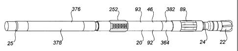
The within invention is comprised of improvements in a drilling direction
control device (20). The device (20) permits directional control over a
drilling bit (22)
connected with the device (20) during rotary drilling operations by
controlling the
deflection of the drilling bit (22). As a result, the direction of the
resulting wellbore may
be controlled.
In particular, the invention relates to improvements in a drilling shaft
deflection assembly for bending a drilling shaft and in an indexing assembly
for
orienting the direction of the bend in a drilling shaft to provide a desired
toolface.
1. General Description of the Drilling Direction Control Device (20) (Figures
1,2,7)
The invention is particularly suited for use with a drilling direction control
device of the type described in U.S. Patent No. 6,244,361 B1 (Halliburton
Ener~y
Services, Inc.), with the result that many of the components of the drilling
direction
control device described in U.S. Patent No. 6,244,361 B1 may be used with the
drilling
direction control device of the present invention.
-31-
CA 02351978 2001-06-28
The drilling direction control device (20) is comprised of a rotatable
drilling shaft (24) which is connectable or attachable to a rotary drilling
bit (22) and to a
rotary drilling string (25) during the drilling operation. More particularly,
the drilling
shaft (24) has a proximal end (26) and a distal end (28). The proximal end
(26) is
drivingly connectable or attachable with the rotary drilling string (25) such
that rotation
of the drilling string (25) from the surface results in a corresponding
rotation of the
drilling shaft (24). The proximal end (26) of the drilling shaft (24) may be
permanently
or removably attached, connected or otherwise affixed with the drilling string
(25) in
any manner and by any structure, mechanism, device or method permitting the
rotation
of the drilling shaft (24) upon the rotation of the drilling string (25).
Preferably, the device (20) is further comprised of a drive connection (29)
for connecting the drilling shaft (24) with the drilling string (25). The
drive connection
(29) may be comprised of any structure, mechanism or device for drivingly
connecting
the drilling shaft (24) and the drilling string (25) so that rotation of the
drilling string
(25) results in a corresponding rotation of the drilling shaft (24).
Similarly, the distal end (28) of the drilling shaft (24) is drivingly
connectable or attachable with the rotary drilling bit (22) such that rotation
of the
drilling shaft (24) by the drilling string (25) results in a corresponding
rotation of the
drilling bit (22). The distal end (28) of the drilling shaft (24) may be
permanently or
removably attached, connected or otherwise affixed with the drilling bit (22)
in any
manner and by any structure, mechanism, device or method permitting the
rotation of
the drilling bit (22) upon the rotation of the drilling shaft (24). In the
preferred
embodiment, a threaded connection is provided therebetween.
The drilling shaft (24) may be comprised of one or more elements or
portions connected, attached or otherwise affixed together in any suitable
manner
providing a unitary drilling shaft (24) between the proximal and distal ends
(26, 28).
-32-
CA 02351978 2001-06-28
Preferably, any connections provided between the elements or portions of the
drilling
shaft (24) are relatively rigid such that the drilling shaft (24) does not
include any
flexible joints or articulations therein. In the preferred embodiment, the
drilling shaft
(24) is comprised of a single, unitary or integral element extending between
the
proximal and distal ends (26, 28). Further, the drilling shaft (24) is tubular
or hollow to
permit drilling fluid to flow therethrough in a relatively unrestricted or
unimpeded
manner.
Finally, the drilling shaft (24) may be comprised of any material suitable
for and compatible with rotary drilling. In the preferred embodiment, the
drilling shaft
(24) is comprised of high strength stainless steel.
Further, the device (20) is comprised of a housing (46) for rotatably
supporting a length of the drilling shaft (24) for rotation therein upon
rotation of the
attached drilling string (25). The housing (46) may support, and extend along,
any
length of the drilling shaft (24). However, preferably, the housing (46)
supports
substantially the entire length of the drilling shaft (24) and extends
substantially
between the proximal and distal ends (26, 28) of the drilling shaft (24).
In the preferred embodiment, the housing (46) has a proximal end (48)
adjacent or in proximity to the proximal end (26) of the drilling shaft (24).
Specifically,
the proximal end (26) of the drilling shaft (24) extends from the proximal end
(48) of the
housing (46) for connection with the drilling string (25). However, in
addition, a
portion of the adjacent drilling string (25) may extend within the proximal
end (48) of
the housing (46). Similarly, in the preferred embodiment, the housing (46) has
a distal
end (50) adjacent or in proximity to the distal end (28) of the drilling shaft
(24).
Specifically, the distal end (28) of the drilling shaft (24) extends from the
distal end (50)
of the housing (46) for connection with the drilling bit (22).
-33-
CA 02351978 2001-06-28
The housing (46) may be comprised of one or more tubular or hollow
elements, sections or components permanently or removably connected, attached
or
otherwise affixed together to provide a unitary or integral housing (46)
permitting the
drilling shaft (24) to extend therethrough.
The device (20) is further comprised of at least one distal radial bearing
(82) which is contained within the housing (46) for rotatably supporting the
drilling
shaft (24) radially at a distal radial bearing location (86) defined thereby.
The distal radial bearing (82) is comprised of a fulcrum bearing (88), also
referred to as a focal bearing, or some other bearing which facilitates the
pivoting of the
drilling shaft (24) at the distal radial bearing location (86) upon the
controlled deflection
of the drilling shaft (24) by the device (20) to produce a bending or
curvature of the
drilling shaft (24) in order to orient or direct the drilling bit (22).
The device (20) may optionally be further comprised of a near bit stabilizer
(89), preferably located adjacent to the distal end (50) of the housing (46)
and preferably
coinciding with the distal radial bearing location (86). The near bit
stabilizer (89) may
be comprised of any type of stabilizer and may be either adjustable or non-
adjustable.
The device (20) is further comprised of at least one proximal radial bearing
(84) which is contained within the housing (46) for rotatably supporting the
drilling
shaft (24) radially at a proximal radial bearing location (90) defined
thereby.
The proximal radial bearing (84) may be comprised of any radial bearing
able to rotatably radially support the drilling shaft (24) within the housing
(46) at the
proximal radial bearing location (90), but the proximal radial bearing (84) is
preferably
comprised of a cantilever bearing.
-34-
CA 02351978 2001-06-28
Upon deflection of the drilling shaft (24) by the device (20), as described
further below, the curvature or bending of the drilling shaft (24) is produced
downhole
of the cantilever proximal radial bearing (84). In other words, the deflection
of the
drilling shaft (24), and thus the curvature of the drilling shaft (24), occurs
between the
proximal radial bearing location (90) and the distal radial bearing location
(86). The
cantilever nature of the proximal radial bearing (84) inhibits the bending of
the drilling
shaft (24) uphole or above the proximal radial bearing (84). The fulcrum
bearing
comprising the distal radial bearing (82) facilitates the pivoting of the
drilling shaft (24)
and permits the drilling bit (22) to tilt in any desired direction.
Specifically, the drilling
bit (22) is permitted to tilt in the opposite direction of the bending
direction.
The device (20) is further comprised of a drilling shaft deflection assembly
(92) contained within the housing (46) for bending the drilling shaft (24)
therein. The
drilling shaft deflection assembly (92) is located axially at a location
between the distal
radial bearing location (86) and the proximal radial bearing location (90) so
that the
deflection assembly (92) bends the drilling shaft (24) between the distal
radial bearing
location (86) and the proximal radial bearing location (90). Various
embodiments of the
drilling shaft deflection assembly (92) are described in detail below.
The device (20) may also be further comprised of an indexing assembly
(93) contained within the housing (46) for orienting the deflection mechanism
to
provide a desired toolface. The indexing assembly (93) may be integrated with
the
deflection assembly (92) or it may be comprised of a separate apparatus.
Various
embodiments of the indexing assembly (93) are described in detail below.
In addition to the radial bearings (82, 84) for rotatably supporting the
drilling shaft (24) radially, the device (20) further preferably includes one
or more thrust
bearings for rotatably supporting the drilling shaft (24) axially.
-35-
CA 02351978 2001-06-28
Preferably, the device (20) is comprised of at least one distal thrust bearing
(94) and at least one proximal thrust bearing (96). The thrust bearings (94,
96) may be
positioned at any locations along the length of the drilling shaft (24)
permitting the
bearings (94, 96) to rotatably support the drilling shaft (24) axially within
the housing
(46).
Preferably, at least one distal thrust bearing (94) is located axially at a
distal thrust bearing location (98) which is preferably located axially
between the distal
end (50) of the housing (46) and the deflection assembly (92). The distal
thrust bearing
(94) may be comprised of any suitable thrust bearing but is preferably
comprised of the
fulcrum bearing (88) described above so that the distal thrust bearing
location (98) is at
the distal radial bearing location (86).
Preferably at least one proximal thrust bearing (96) is located axially at a
proximal thrust bearing location (100) which is preferably located axially
between the
proximal end (48) of the housing (46) and the deflection assembly (92). Most
preferably
the proximal thrust bearing location (100) is located axially between the
proximal end
(48) of the housing (46) and the proximal radial bearing location (90). The
proximal
thrust bearing (96) may be comprised of any suitable thrust bearing.
As a result of the thrust bearings (94, 96), most of the weight on the
drilling bit (22) may be transferred into and through the housing (46) as
compared to
through the drilling shaft (24) of the device (20). Thus, the drilling shaft
(24) may be
permitted to be slimmer and more controllable. As well, most of the drilling
weight
bypasses the drilling shaft (24) substantially between its proximal and distal
ends (48,
50) and thus bypasses the other components of the device (20) including the
deflection
assembly (92). More particularly, weight applied on the drilling bit (22)
through the
drill string (25) is transferred, at least in part, from the drilling string
(25) to the
proximal end (48) of the housing (46) by the proximal thrust bearing (96) at
the
-36-
CA 02351978 2001-06-28
proximal thrust bearing location (100). The weight is further transferred, at
least in
part, from the distal end (50) of the housing (46) to the drilling shaft (24),
and thus the
attached drilling bit (22), by the fulcrum bearing (88) at the distal thrust
bearing location
(100).
The thrust bearings (94, 96) are preferably preloaded. Any mechanism,
structure, device or method capable of preloading the thrust bearings (94, 96)
may be
utilized.
Due to rotation of the drilling shaft (24) during rotary drilling, there will
be a tendency for the housing (46) to rotate during the drilling operation. As
a result,
the device (20) is preferably comprised of an anti-rotation device (252)
associated with
the housing (46) for restraining rotation of the housing (46) within the
wellbore. Any
type of anti-rotation device (252) or any mechanism, structure, device or
method
capable of restraining or inhibiting the tendency of the housing (46) to
rotate upon
rotary drilling may be used. Further, one or more such devices (252) may be
used as
necessary to provide the desired result.
As well, the device (252) may be associated with any portion of the
housing (46). In other words, the anti-rotation device (252) may be located at
any
location or position along the length of the housing (46) between its proximal
and distal
ends (48, 50). The anti-rotation device (252) may be associated with the
housing (46) in
any manner permitting the functioning of the device (252) to inhibit or
restrain rotation
of the housing (46).
In addition, the drilling direction control device (20) is preferably further
comprised of one or more seals or sealing assemblies for sealing the distal
and proximal
ends (50, 48) of the housing (46) such that the components of the device (20)
located
therebetween are not exposed to various drilling fluids, such as drilling mud.
In
-37-
CA 02351978 2001-06-28
addition to inhibiting the entrance of drilling fluids into the device (20)
from outside,
the seals or sealing assemblies also facilitate the maintenance or retention
of desirable
lubricating fluids within the device (20).
Preferably, the device (20) is comprised of a distal seal or sealing assembly
(280) and a proximal seal or sealing assembly (282). The distal seal (280) is
radially
positioned and provides a rotary seal between the housing (46) and the
drilling shaft
(24) at, adjacent or in proximity to the distal end (50) of the housing (46).
The proximal seal (282) is radially positioned and provides a rotary seal
between the housing (46) and the drilling shaft (24) at, adjacent or in
proximity to the
proximal end (48) of the housing (46). However, where the drilling string (25)
extends
within the proximal end (48) of the housing (46), the proximal seal (282) is
more
particularly positioned between the housing (46) and the drilling string (25).
Thus, the
proximal seal (282) is radially positioned and provides a seal between the
drilling shaft
(24) or the drilling string (25) and the housing (46) at, adjacent or in
proximity to the
proximal end (48) of the housing.
As well, the interior of the housing (46) preferably defines a fluid chamber
(284) between the distal and proximal ends (50, 48) of the housing (46). Thus,
the fluid
chamber (284) is positioned or defined between the distal and proximal seals
(280, 282)
associated with the distal and proximal ends (50, 48) of the housing (46)
respectively.
As indicated above, the fluid chamber (284) is preferably filled with a
lubricating fluid
for lubricating the components of the device (20) within the housing (46).
The distal and proximal seals (280, 282) are preferably mounted about the
drilling shaft (24) and drilling string (25) respectively such that the
drilling shaft (24)
and attached drilling string (25) are permitted to rotate therein while
maintaining the
sealing. Further, the distal and proximal seals (280, 282) preferably provide
a flexible
-38-
CA 02351978 2001-06-28
sealing arrangement or flexible connection between the housing (46) and the
drilling
shaft (24) or drilling string (25) in order to maintain the seal provided
thereby, while
accommodating any movement or deflection of the drilling shaft (24) or
drilling string
(25) within the housing (46). This flexible connection is particularly
important for the
distal seal (280) which is exposed to the pivoting of the drilling shaft (24)
by the
deflection assembly (92). A suitable sealing arrangement is described in
detail in U.S.
Patent No. 6,244,361 B1 (Halliburton Energy Services, Inc.).
The lubricating fluid contained within the fluid chamber (284) of the
housing (46) between the proximal and distal seals (282, 280) has a pressure.
Preferably,
the device (20) is further comprised of a pressure compensation system (326)
for
balancing the pressure of the lubricating fluid contained in the fluid chamber
(284)
within the housing (46) with the ambient pressure outside of the housing (46).
The
pressure compensation system (326) may be located at any position or location
along
the length of the housing (46) between the distal and proximal seals (280,
282).
The pressure compensation system (326) may be comprised of any
mechanism, device or structure capable of providing for or permitting the
balancing of
the pressure of the lubricating fluid contained in the fluid chamber (284)
with the
ambient pressure outside of the housing (46). Preferably, the pressure
compensation
system (326) is comprised of at least one pressure port (328) in the housing
(46) so that
the ambient pressure outside of the housing (46) can be communicated to the
fluid
chamber (284).
Preferably, the pressure of the lubricating fluid contained in the fluid
chamber (284) of the housing (46) is maintained higher than the ambient
pressure
outside of the housing (46) or the annulus pressure in the wellbore.
Specifically, the
pressure compensation system (326) preferably internally maintains a positive
pressure
across the distal and proximal seals (280, 282). As a result, in the event
there is any
-39-
CA 02351978 2001-06-28
tendency for the distal and proximal seals (280, 282) to leak and permit the
passage of
fluid across the seals (280, 282), the passage of any such fluid will tend to
be lubricating
fluid from within the fluid chamber (284) to outside of the device (20).
In order to provide a pressure within the fluid chamber (284) of the
housing (46) higher than the outside annulus pressure, the pressure
compensation
system (326) is further preferably comprised of a supplementary pressure
source (330).
The supplementary pressure source (330) exerts pressure on the lubricating
fluid
contained in the fluid chamber (284) so that the pressure of the lubricating
fluid
contained in the fluid chamber (284) is maintained higher than the ambient
pressure
outside of the housing (46). The pressure differential between the fluid
chamber (284)
and outside the housing (46) may be selected according to the expected
drilling
conditions. However, preferably, only a slightly positive pressure is provided
in the
fluid chamber (284) by the supplementary pressure source (330).
The supplementary pressure may be provided in any manner or by any
method, and the supplementary pressure source (330) may be comprised of any
structure, device or mechanism, capable of providing the desired supplementary
pressure within the fluid chamber (284) to generate the desired pressure
differential
between the fluid chamber (284) and outside the housing (46).
Preferably the pressure compensation system (326) is further comprised of
a balancing piston assembly (336) which includes a movable piston (340)
contained
within a piston chamber (338). The piston (340) separates the piston chamber
(338) into
a fluid chamber side (342) and a balancing side (344). The fluid chamber side
(342) is
connected with the fluid chamber (284) and is preferably located distally or
downhole
of the piston (340). The pressure port (328) communicates with the balancing
side (344)
of the piston chamber (338), which is preferably located proximally or uphole
of the
piston (340). Further, the supplementary pressure source (330) acts on the
balancing
-40-
CA 02351978 2001-06-28
side (344) of the piston chamber (338). Specifically, the supplementary
pressure source
(330) acts on the balancing side (344) by exerting the supplementary pressure
on the
piston (340).
Preferably the supplementary pressure source (330) is comprised of a
biasing device located within the balancing side (344) of the piston chamber
(338) and
which exerts the supplementary pressure on the piston (340). The biasing
device may
be comprised of any device, structure or mechanism capable of biasing the
piston (340)
in the manner described above. Preferably the biasing device is comprised of a
spring
(346).
Preferably the device (20) has the capability to communicate electrical
signals between two members which rotate relative to each other without having
any
contact therebetween. For example, this communication is required when
downloading
operating parameters for the device (20) or communicating downhole information
from
the device (20) either further uphole along the drilling string (25) or to the
surface.
Specifically, the electrical signals must be communicated between the drilling
shaft (24)
and the housing (46), which rotate relative to each other during the rotary
drilling
operation.
The communication link between the drilling shaft (24) and the housing
(46) may be provided by any direct or indirect coupling or communication
method or
any mechanism, structure or device for directly or indirectly coupling the
drilling shaft
(24) with the housing (46). For instance, the communication between the
housing (46)
and the drilling shaft (24) may be provided by a slip ring or a gamma-at-bit
communication toroid coupler. However, in the preferred embodiment, the
communication between the drilling shaft (24) and the housing (46) is provided
by an
electromagnetic coupling device (350) between the housing (46) and the
drilling shaft.
-41-
CA 02351978 2001-06-28
The deflection assembly (92) and the indexing assembly (93) may be
actuated manually. Preferably, however, the device (20) is further comprised
of a
controller (360) for controlling the actuation of the drilling shaft
deflection assembly (92)
and the indexing assembly (93) to provide directional drilling control. The
controller
(360) of the device (20) is preferably associated with the housing (46) and is
preferably
comprised of an electronics insert positioned within the housing (46).
Information or
data provided by the various downhole sensors of the device (20) is
communicated to
the controller (360) in order that the deflection assembly (92) and the
indexing assembly
(93) may be actuated with reference to and in accordance with the information
or data
provided by the sensors.
The drilling direction control device (20) is preferably comprised of a
housing orientation sensor apparatus (362) which is associated with the
housing (46) for
sensing the orientation of the housing (46) within the wellbore. Since the
housing (46) is
substantially restrained from rotating during drilling, the orientation of the
housing (46)
which is sensed by the housing orientation sensor apparatus (362) provides the
reference orientation for the device (20).
The housing orientation sensor apparatus (362) may be comprised of any
sensor or sensors, such as one or a combination of magnetometers and
accelerometers,
capable of sensing the orientation of the housing (46). The housing
orientation sensor
apparatus (362) is preferably located as close as possible to the distal end
(50) of the
housing (46). The housing orientation sensor apparatus (362) preferably senses
the
orientation of the housing (46) in three dimensions in space. Alternatively,
the housing
orientation sensor apparatus (362) may be designed to sense the orientation of
the
housing (46) in fewer than three dimensions. For example, the housing
orientation
sensor apparatus (362) may be designed to sense the orientation of the housing
(46)
relative to gravity and/or the earth's magnetic field. A preferred embodiment
of
housing orientation sensor apparatus (362) is described in detail below.
-42-
CA 02351978 2001-06-28
Preferably the housing orientation sensor apparatus (362) is contained
within or is part of an ABI or at-bit-inclination insert associated with the
housing (46).
Preferably, the ABI insert (364) is connected or mounted with the housing (46)
at,
adjacent or in close proximity with its distal end (68). Referring to Figures
1(a) and 1(b),
the ABI insert (364) is depicted as located distally of the deflection
assembly (92).
Referring to Figure 7(d), the ABI insert (364) is depicted as located
proximally of the
deflection assembly (92). Either configuration is possible, with the preferred
configuration depending upon the design of the deflection assembly (92), the
indexing
assembly (93) and the other components of the drilling direction control
device (20).
The drilling direction control device (20) may also be comprised of a
deflection assembly orientation sensor apparatus (366) associated with the
deflection
assembly (92) for sensing the orientation of the deflection mechanism.
Alternatively the
deflection mechanism may be designed to maintain a constant orientation
relative to the
housing (46) so that the orientation of the deflection mechanism can be
determined
from the orientation of the housing (46), thus eliminating the need for a
separate
deflection assembly orientation sensor apparatus (366).
Where provided, the deflection assembly orientation sensor apparatus
(366) preferably senses the orientation of the deflection mechanism relative
to the
housing (46). However, the deflection assembly orientation sensor apparatus
(366) may
also sense the orientation of the deflection mechanism without reference to
the
orientation of the housing (46), in which case it may be possible to eliminate
the housing
orientation sensor apparatus (362).
The deflection assembly orientation sensor apparatus (366) may be
comprised of any sensor or sensors, such as one or a combination of
magnetometers
-43-
CA 02351978 2001-06-28
and accelerometers, capable of sensing the position of the deflection assembly
(92) in
space or relative to the housing (46).
The controller (360) may also be operatively connected with a drilling
string orientation sensor apparatus (376) so that the deflection assembly (92)
and the
indexing assembly (93) may further be actuated with reference to the
orientation of the
drilling string (25). The drilling string orientation sensor apparatus (376)
is connected,
mounted or otherwise associated with the drilling string (25). The controller
(360) may
be operatively connected with the drilling string orientation sensor apparatus
(376) in
any manner and by any mechanism, structure, device or method permitting or
providing for the communication of information or data therebetween. However,
preferably, the operative connection between the controller (360) and the
drilling string
orientation sensor apparatus (376) is provided by the electromagnetic coupling
device
(350).
The drilling string orientation sensor apparatus (376) may be comprised of
any sensor or sensors, such as one or a combination of magnetometers and
accelerometers, capable of sensing the orientation of the drilling string
(25)). In
addition, the drilling string orientation sensor apparatus (376) preferably
senses the
orientation of the drilling string (25) in three dimensions in space.
The deflection assembly (92) and the indexing assembly (93) are therefore
preferably actuated to reflect a desired orientation of the drilling string
(25) by taking
into consideration the orientation of the drilling string (25), the
orientation of the
housing (46) and the orientation of the deflection assembly (92) relative to
the housing
(46).
As well, while drilling, the housing (46) may tend to slowly rotate in the
same direction of rotation of the drilling shaft (24) due to the small amount
of torque
-44-
CA 02351978 2001-06-28
that is transmitted from the drilling shaft (24) to the housing (46). This
motion causes
the toolface of the drilling bit (22) to move out of the desired position. The
various
sensor apparatuses (362, 366, 376) may sense this change and communicate the
information to the controller (360). The controller (360) preferably keeps the
toolface of
the drilling bit (22) on target by automatically adjusting the orientation of
the deflection
mechanism to compensate for the rotation of the housing (46).
In order that information or data may be communicated along the drilling
string (25) from or to downhole locations, such as from or to the controller
(360) of the
device (20), the device (20) may be comprised of a drilling string
communication system
(378). More particularly, the drilling string orientation sensor apparatus
(376) is also
preferably operatively connected with the drilling string communication system
(378)
so that the orientation of the drilling string (25) may be communicated to an
operator of
the device (20). The operator of the device (20) may be either a person at the
surface in
charge or control of the drilling operations or may be comprised of a computer
or other
operating system for the device (20).
The drilling string communication system (378) may be comprised of any
system able to communicate or transmit data or information from or to downhole
locations. However, preferably, the drilling string communication system (378)
is
comprised of an MWD or Measurement-While-Drilling system or device.
The device (20) may be comprised of any further number of sensors as
required or desired for any particular drilling operation, such as sensors for
monitoring
other internal parameters of the device (20).
The device (20) may be further comprised of a device memory (380) for
storing data generated by one or more of the housing orientation sensor
apparatus
(362), the deflection assembly orientation sensor apparatus (366), the
drilling string
-45-
CA 02351978 2001-06-28
orientation sensor apparatus (376) or data obtained from some other source
such as, for
example an operator of the device (20). The device memory (380) is preferably
associated with the controller (20), but may be positioned anywhere between
the
proximal and distal ends (48, 50) of the housing (46), along the drilling
string (25), or
may even be located outside of the borehole. During operation of the device
(20), data
may be retrieved from the device memory (380) as needed in order to control
the
operation of the device (20), including the actuation of the deflection
assembly (92) and
the indexing assembly (93).
Finally, the device (20) may be further comprised of a housing locking
assembly (382) for selectively engaging the housing (46) with the drilling
shaft (24) so
that the drilling shaft (24) and the housing (46) will rotate together. This
housing
locking assembly (382) is particularly advantageous in circumstances where the
housing
(46) has become stuck in a wellbore, since the application of torque to the
housing (46)
via the drilling string (25) and the drilling shaft (24) may be sufficient to
dislodge the
housing (46). A preferred embodiment of housing locking assembly (382) is
described
in detail below.
2. Detailed Description of Deflection Assembly (92)
As indicated above, the device (20) includes a drilling shaft deflection
assembly (92) contained within the housing (46), for bending the drilling
shaft (24). The
deflection assembly (92) may be comprised of any structure or apparatus
capable of
bending the drilling shaft (24) or deflecting the drilling shaft (24)
laterally or radially
within the housing (46) and having the following basic components:
(a) a deflection mechanism (384) for imparting lateral movement to the
drilling shaft (24) in order to bend the drilling shaft (24);
-46-
CA 02351978 2001-06-28
(b) a deflection actuator (386) for actuating the deflection mechanism (384)
in
response to longitudinal movement of the deflection actuator (386); and
(c) a deflection linkage mechanism (388) between the deflection mechanism
(384) and the deflection actuator (386) for converting longitudinal
movement of the deflection actuator (386) to lateral movement of the
drilling shaft (24).
Figure 7 depicts in detail a drilling direction control device (20) within the
scope of the invention which includes a third preferred embodiment of
deflection
assembly (92). Regardless of the chosen design of deflection assembly (92),
the
components comprising the deflection assembly (92) may be located generally at
the
location of the deflection assembly (92) as depicted in Figure 7(c), with
minor
modification to the device (20) as depicted in Figure 7.
(a) First Preferred Embodiment of Deflection Assembly (92~(Figures 2-5)
In the first preferred embodiment of deflection assembly (92), the
deflection mechanism (384) is comprised of a double ring eccentric mechanism.
Although these eccentric rings may be located a spaced distance apart along
the length
of the drilling shaft (24), preferably, the deflection mechanism (384) is
comprised of an
eccentric outer ring (156) and an eccentric inner ring (158) provided at a
single location
or position along the drilling shaft (24). The rotation of the two eccentric
rings (156,
158) imparts a controlled deflection of the drilling shaft (24) at the
location of the
deflection mechanism (384).
Particularly, the outer ring (156) has a circular outer peripheral surface
(160) and defines therein a circular inner peripheral surface (162). The outer
ring (156),
and preferably the circular outer peripheral surface (160) of the outer ring
(156), is
-47-
CA 02351978 2001-06-28
rotatably supported by or rotatably mounted on, directly or indirectly, the
circular
inner peripheral surface (78) of the housing (46). The circular outer
peripheral surface
(160) may be supported or mounted on the circular inner peripheral surface
(78) by any
supporting structure, mechanism or device permitting the rotation of the outer
ring
(156) relative to the housing (46), such as by a roller bearing mechanism or
assembly.
The circular inner peripheral surface (162) of the outer ring (156) is formed
and positioned within the outer ring (156) such that it is eccentric with
respect to the
housing (46). In other words, the circular inner peripheral surface (162) is
deviated
from the housing (46) to provide a desired degree or amount of deviation.
More particularly, the circular inner peripheral surface (78) of the housing
(46) is centered on the centre of the drilling shaft (24), or the rotational
axis "A" of the
drilling shaft (24), when the drilling shaft (24) is in an undeflected
condition or the
deflection assembly (92) is inoperative. The circular inner peripheral surface
(162) of the
outer ring (156) is centered on point "B" which is deviated from the
rotational axis of
the drilling shaft (24) by a distance "e".
Similarly, the inner ring (158) has a circular outer peripheral surface (166)
and defines therein a circular inner peripheral surface (168). The inner ring
(158), and
preferably the circular outer peripheral surface (166) of the inner ring
(158), is rotatably
supported by or rotatably mounted on, either directly or indirectly, the
circular inner
peripheral surface (162) of the outer ring (156). The circular outer
peripheral surface
(166) may be supported by or mounted on the circular inner peripheral surface
(162) by
any supporting structure, mechanism or device permitting the rotation of the
inner ring
(158) relative to the outer ring (156), such as by a roller bearing mechanism
or assembly.
The circular inner peripheral surface (168) of the inner ring (158) is formed
and positioned within the inner ring (158) such that it is eccentric with
respect to the
-48-
CA 02351978 2001-06-28
circular inner peripheral surface (162) of the outer ring (156). In other
words, the
circular inner peripheral surface (168) of the inner ring (158) is deviated
from the
circular inner peripheral surface (162) of the outer ring (156) to provide a
desired degree
or amount of deviation.
More particularly, the circular inner peripheral surface (168) of the inner
ring (158) is centered on point "C", which is deviated from the centre "B" of
the circular
inner peripheral surface (162) of the outer ring (156) by the same distance
"e". As
described, preferably, the degree of deviation of the circular inner
peripheral surface
(162) of the outer ring (156) from the housing (46), defined by distance "e",
is
substantially equal to the degree of deviation of the circular inner
peripheral surface
(168) of the inner ring (158) from the circular inner peripheral surface (162)
of the outer
ring (156), also defined by distance "e".
The drilling shaft (24) extends through the circular inner peripheral
surface (168) of the inner ring (158) and is rotatably supported thereby. The
drilling
shaft (24) may be supported by the circular inner peripheral surface (168) by
any
supporting structure, mechanism or device permitting the rotation of the
drilling shaft
(24) relative to the inner ring (158), such as by a roller bearing mechanism
or assembly.
As a result of the above described configuration, the drilling shaft (24) may
be moved, and specifically may be laterally or radially deviated within the
housing (46),
upon the movement of the centre of the circular inner peripheral surface (168)
of the
inner ring (158). Specifically, upon the rotation of the inner and outer rings
(158, 156),
either independently or together, the centre of the drilling shaft (24) may be
moved
with the centre of the circular inner peripheral surface (168) of the inner
ring (158) and
positioned at any point within a circle having a radius summed up by the
amounts of
deviation of the circular inner peripheral surface (168) of the inner ring
(158) and the
circular inner peripheral surface (162) of the outer ring (156).
-49-
CA 02351978 2001-06-28
In other words, by rotating the inner and outer rings (158, 156) relative to
each other, the centre of the circular inner peripheral surface (168) of the
inner ring (158)
can be moved in any position within a circle having the predetermined or
predefined
radius as described above. Thus, the portion or section of the drilling shaft
(24)
extending through and supported by the circular inner peripheral surface (168)
of the
inner ring (158) can be deflected by an amount in any direction perpendicular
to the
rotational axis of the drilling shaft (24).
As a result, it is possible with the double eccentric ring configuration
(156,158) to control both the tool face orientation and the amount of
deflection of the
drilling bit (22) connected with the drilling shaft (24).
More particularly, since the circular inner peripheral surface (162) of the
outer ring (156) has the centre B, which is deviated from the rotational
centre A of the
drilling shaft (24) by the distance "e", the locus of the centre B is
represented by a circle
having a radius "e" around the centre A. Further, since the circular inner
peripheral
surface (168) of the inner ring (158) has the centre C, which is deviated from
the centre B
by a distance "e", the locus of the centre "C" is represented by a circle
having a radius
"e" around the centre B. As a result, the centre C may be moved in any desired
position
within a circle having a radius of "2e" around the centre A. Accordingly, the
portion of
the drilling shaft (24) supported by the circular inner peripheral surface
(168) of the
inner ring (158) can be deflected in any direction on a plane perpendicular to
the
rotational axis of the drilling shaft (24) by a distance of up to "2e" (i.e.,
"e" plus "e"),
thus providing for unlimited variation in a "Deflection ON" setting.
In addition, as stated, the deviation distances "e" are preferably
substantially similar in order to permit the operation of the device (20) such
that the
drilling shaft (24) is undeflected within the housing (24) when directional
drilling is not
-50-
CA 02351978 2001-06-28
required. More particularly, since the degree of deviation of each of the
centres B and C
of the circular inner peripheral surface (162) of the outer ring (156) and the
circular
inner peripheral surface (168) of the inner ring (158) respectively is
preferably defined
by the same or equal distance "e", the centre C of the portion of the drilling
shaft (24)
extending through the deflection assembly (92) can be positioned on the
rotational axis
A of the drilling shaft (24) (i.e., "e" minus "e"), in which case the device
(20) is in a zero
deflection mode or is set at a "Deflection OFF" setting.
Providing for unlimited variation in the deflection of the drilling shaft (24)
as described above results in the deflection assembly (92) also providing the
function of
the indexing assembly (93). Although such a dual function deflection assembly
(92)
may be desirable, it may also be relatively complex to construct, operate and
maintain.
As a result, in the first preferred embodiment of deflection assembly (92),
the deflection assembly (92) is configured to operate only in a "Deflection
OFF" setting
and a "Deflection ON" setting. The Deflection OFF setting is provided by
orienting the
eccentric rings (156,158) so that the eccentricities of the inner surfaces of
the rings
(162,168) cancel each other (i.e., "e" minus "e"). The Deflection ON setting
is provided
by orienting the eccentric rings (156,158) so that the eccentricities of the
inner surfaces of
the rings (162,168) add to each other (i.e., "e" plus "e").
This simplified configuration simplifies the actuation of the deflection
assembly (92), but requires a separate indexing step to be performed in order
to orient
the bend in the drilling shaft (24) to achieve a desired toolface orientation.
The deflection mechanism comprising the inner and outer rings (158, 156)
may be actuated by any suitable combination of longitudinally movable
deflection
actuator (386) and deflection linkage mechanism (388). Preferably the inner
and outer
-51-
CA 02351978 2001-06-28
rings (158,156) are actuated either directly or indirectly using the rotation
of the drilling
shaft (24).
In the first preferred embodiment of deflection assembly (92), the
deflection actuator (384) is comprised of a longitudinally movable sleeve cam
(390).
In the first preferred embodiment of deflection assembly (92), the
deflection linkage mechanism (388) is provided by a first track (392) and a
second track
(394) in the sleeve cam (390) which engage a rotatable first deflection
linkage member
(396) and a rotatable second deflection linkage member (398).
It is noted that the sleeve cam (390) is capable of longitudinal movement
but not rotation, while the deflection linkage members (396,398) are capable
of rotation
but not longitudinal movement. In this manner, longitudinal movement of the
sleeve
cam (390) is converted to rotation of the deflection linkage members
(396,398).
The first deflection linkage member (396) in turn is connected with one of
the outer ring (156) and the inner ring (158) and the second deflection
linkage member
(398) is connected with the other of the outer ring (156) and the inner ring
(158).
At least one of the tracks (392,394) is a spiral track. If both of the tracks
(392,394) are spiral tracks, they either spiral in opposite directions or at
different rates so
that longitudinal movement of the sleeve cam (390) will cause the deflection
linkage
members (396,398) to move in the tracks (392,398) and will cause the rings
(156,158) to
rotate either in different directions or at different rates.
Referring to Figure 5, the sleeve cam (390) is comprised of a hollow tube,
the first deflection linkage member (396) is comprised of a hollow tube
telescopically
-52-
CA 02351978 2001-06-28
received within the sleeve cam (390), and the second deflection linkage member
(398) is
a hollow tube telescopically received within the first deflection linkage
member (396).
Referring to Figure 5, the first track (392) is comprised of a continuous
channel in the sleeve cam which engages a first pin (400) on the first
deflection linkage
member (396). Similarly, the second track (394) is comprised of a continuous
channel in
the sleeve cam (390) which engages a second pin (402) on the second deflection
linkage
member (398). Preferably a gate mechanism (not shown) is provided for each of
the
track/pin assemblies to restrict movement of the pins in the tracks to one
direction.
Referring to Figure 3, the first track (392) is a spiral track and the second
track (394) is a straight track, so that the first deflection linkage member
(396) will
impart rotation to one of the rings (156,158) upon longitudinal movement of
the sleeve
cam (390) while the second deflection linkage member (398) will impart no
rotation to
the other of the rings (156,158) upon longitudinal movement of the sleeve cam
(390).
Referring to Figure 4, the first track (392) is a spiral track and the second
track (394) is also a spiral track in the opposite direction, so that the
first deflection
linkage member (396) will impart rotation to one of the rings (156,158) in one
direction
upon longitudinal movement of the sleeve cam (390) while the second deflection
linkage member (398) will impart rotation to the other of the rings (156,158)
in the
opposite direction upon longitudinal movement of the sleeve cam (390). The
embodiment of sleeve cam (390) depicted in Figure 4 facilitates a shorter
sleeve cam
(390) than the embodiment of sleeve cam (390) depicted in Figure 3.
The deflection linkage members (396,398) each include a drive end (404) to
which the rings (156,158) may be directly or indirectly connected to provide
for
actuation of the deflection mechanism (384).
-53-
CA 02351978 2001-06-28
The reciprocation of the sleeve cam (390) is powered by a power source
(406). Referring to Figure 7(c), the preferred power source (406) for the
deflection
assembly (92) is comprised of a hydraulic pump, a cylinder, and a piston which
is either
directly or directly connected with the sleeve cam (390). Preferably the power
source
(406) is double acting so that it provides power to reciprocate the sleeve cam
in opposite
directions, in order to move the deflection mechanism (384) between a
Deflection OFF
position and a Deflection ON position.
The deflection assembly (92) as described above may thus be used to
provide deflection of the drilling shaft (24). Indexing of the deflection
mechanism (384)
to provide a desired toolface orientation can then be provided by a separate
indexing
assembly (93) such as the embodiments of indexing assembly (93) describe
below.
Alternatively, in the first preferred embodiment of deflection assembly
(92), the indexing assembly (93) may be comprised of an "extension" of the
deflection
assembly (92). Specifically, and referring to Figures 3-5, each of the first
track (392) and
the second track (394) may be comprised of a deflection segment (407) and an
indexing
segment (409).
The deflection segments (407) of the tracks (392,394) serve to deflect and
straighten the drilling shaft (24) while the indexing segments (409) of the
tracks
(392,394) serve to rotate both rings (156,158) at the same rate and in the
same direction
in order to orient the direction of the bend in the drilling shaft (24). Each
cycle of
actuation of the sleeve cam through the indexing segments (409) will provide a
predetermined rotation of the deflection mechanism (384) which depends upon
the
shape and slope of the spiral of the indexing segments (409).
Finally, if the deflection assembly (92) is not intended to perform an
indexing function, it is possible to omit the second deflection linkage
mechanism,
-54-
CA 02351978 2001-06-28
including the second track (394), the second pin (402), and the second
deflection linkage
member (398), since the drilling shaft (24) can be bent simply by rotation of
one of the
rings (156,158) relative to the other ring without any need for rotating the
other ring.
Indexing of the deflection mechanism (384) can then be performed by a separate
indexing assembly (93).
(b) Second Preferred Embodiment of Deflection Assembl,~92~(Figure 6)
The second preferred embodiment of deflection assembly (92) is
essentially a variation of the first embodiment of deflection assembly (92).
The
difference between the two embodiments relates primarily to the design of the
deflection mechanism (384).
Specifically, the outer ring (156) of the first preferred embodiment is
replaced with a rotary camming surface (408) and the inner ring (158) is
replaced with a
follower member (410). Rotation of the camming surface (408) relative to the
follower
member (410) will serve to deflect the drilling shaft (24). Coordinated
rotation of both
the caroming surface (408) and the follower member (410) may serve to index
the
deflection mechanism (384) to provide a desired orientation for the bend in
the drilling
shaft (24).
Longitudinal movement of the deflection actuator (386) is therefore
converted by the deflection linkage mechanism (388) and the deflection
mechanism
(384) into deflection of the drilling shaft (24). Similarly, longitudinal
movement of the
deflection actuator (386) may be used to provide an indexing function as
described
above with respect to the first preferred embodiment of deflection assembly
(92).
(c) Third Preferred Embodiment of Deflection Assembly~92;~ (Figures 7-13)
-55-
CA 02351978 2001-06-28
The third embodiment of deflection assembly (92) may be implemented in
many designs which fall within the scope of the invention. Two such designs
are
depicted in Figures 7-13.
In the third embodiment, the deflection mechanism (384) is comprised of
at least one follower member (410), and the deflection linkage mechanism (388)
is
comprised of at least one longitudinally movable camming surface (412). The
deflection
actuator (386) is comprised of a longitudinally movable deflection actuator
member
(414).
The follower member (410) is capable of lateral movement between the
housing (46) and the drilling shaft (24) but is not capable of longitudinal
movement.
The follower member (410) directly or indirectly engages the drilling shaft
(24) so that
lateral movement of the follower member (410) results in lateral movement of
the
drilling shaft (24).
The actuation of the deflection assembly (92) is powered by the power
source (406). An exemplary power source is depicted in Figure 7(c) and
schematically
in Figure 8. Preferably the power source (406) is double acting in order to
provide
power to move the caroming surface or surfaces (412) in opposite directions.
The caroming surface (412) may be integrated with the deflection actuator
member (414) or it may be a separate component which is connected with the
deflection
actuator member (414).
The follower member (410) and the caroming surface (412) provide
complementary ramp surfaces which engage each other to move the follower
member
(410) laterally in response to longitudinal movement of the caroming surface.
The
lateral movement of the follower member results in deflection of the drilling
shaft (24).
-56-
CA 02351978 2001-06-28
The follower member (410) may include a plurality of follower member
surfaces (416) for engaging a plurality of camming surfaces (412). This
configuration of
follower member is useful either for providing support for opposing sides of
the
drilling shaft (24) in the case of uni-axial deflection, or for facilitating
multi-axial
deflection of the drilling shaft (24) with a single follower member (410).
Alternatively,
the same results can be achieved with a plurality of follower members (410).
Figure 7(c) and Figures 8-10 depict a deflection assembly (92) which
provides for uni-axial deflection of the drilling shaft (24).
Figures 7(c), 9 and 10 depict a uni-axial deflection mechanism (384) which
includes a single camming surface (412), a single follower member (410) and a
single
follower member surface (416). The disadvantage to this configuration is that
the
drilling shaft (24) is not supported in two positions at the location of the
bend, with the
result that the drilling shaft (24) may be prone to whipping or buckling at
the location
of the bend.
Figure 8 depicts schematically a uni-axial deflection mechanism (384)
which includes two caroming surfaces (412), a single follower member (410),
and two
follower member surfaces (416). It is noted that the complementary ramp
surfaces for
the two sets of caroming surface (412) / follower member surface (416) are
directed in
opposing directions to accommodate both bending and support of the drilling
shaft
(24). This configuration for uni-axial bending of the drilling shaft
facilitates support for
the drilling shaft (24) both above and below the bend.
Figures 11-13 depict a deflection assembly (92) which provides for bi-axial
deflection of the drilling shaft (24).
-57-
CA 02351978 2001-06-28
This bi-axial deflection may be achieved by providing two independent
deflection assemblies (92) which provide deflection about different axes.
Alternatively,
and as depicted in Figures 11-13, bi-axial deflection may be achieved by
duplicating
some components of the deflection assembly (92) while sharing other components
of the
deflection assembly (92).
Specifically, Figure 13 depicts a single follower member (410) which
includes four follower member surfaces (416). Two follower member surfaces
(416) are
utilized for bending the drilling shaft (24) about an axis, in order to
provide two
positions of support for the drilling shaft (24) (i.e., above and below the
bend).
Deflection in a single axis therefore requires movement of two separate
camming surfaces (412) relative to two follower member surfaces (416).
Referring to
Figure 12, this may be accomplished by providing a deflection linkage member
(418)
which includes two opposed caroming surfaces (412). The deflection linkage
member
(418) is connected with or is part of the deflection actuator member (414).
Longitudinal
movement of the deflection actuator member (414) results in longitudinal
movement of
the deflection linkage member (418) and thus longitudinal movement of the two
caroming surfaces (412).
Deflection in two axes is accomplished by providing two separate
deflection actuators (386) and two separate deflection linkage mechanisms
(388), while
maintaining a single deflection mechanism (384). Each deflection actuator
(386)
comprises a deflection actuator member (414) and each deflection linkage
mechanism
(388) comprises a deflection linkage member (418). The deflection actuators
may be
powered by a common power source (406) or by separate power sources (406).
In the embodiment of deflection assembly (92) which facilitates bi-axial
deflection of the drilling shaft (24) with a single follower member (410) as a
deflection
-58-
CA 02351978 2001-06-28
mechanism (384), forced lateral motion of the follower member (410) must be
addressed. In other words, lateral movement of the follower member (410) along
one
axis will result in relative transverse movement between the caroming surfaces
(412)
and the follower member surfaces (416) which are parallel to the plane of the
lateral
movement. In the preferred embodiment as depicted in Figure 13, forced lateral
motion
is addressed by providing relatively large planar follower member surfaces
(416) and
by ensuring that the caroming surfaces (412) and the follower member surfaces
(416)
accommodate the forced lateral motion, either by choice of materials or by
choice of any
bearings which may be provided between the caroming surfaces (412) and the
follower
member surfaces (416).
3. Detailed Description of Indexing Assembl,~(93)
The indexing assembly (93) may be comprised of any structure or
apparatus which is capable of orienting the deflection mechanism (384) to
achieve a
desired toolface orientation.
The invention encompasses any indexing assembly (93) which includes
the following basic components:
(a) an indexing mechanism (420) for imparting rotational movement to the
deflection mechanism (384);
(b) an indexing actuator (422) for actuating the indexing mechanism (420) in
response to longitudinal movement of the indexing actuator (422); and
(c) an indexing linkage mechanism (424) between the indexing mechanism
(420) and the indexing actuator (422) for converting longitudinal
-59-
CA 02351978 2001-06-28
movement of the indexing actuator (422) to rotational movement of the
deflection mechanism (384).
Figure 7 depicts in detail a drilling direction control device (20) within the
scope of the invention which includes a first preferred embodiment of indexing
assembly (93). Regardless of the chosen design of indexing assembly (93), the
components comprising the indexing assembly (93) may be located generally at
the
location of the indexing assembly (93) as depicted in Figure 7(c), with minor
modification to the device (20) as depicted in Figure 7.
(a) First Preferred Embodiment of Indexing Assembh 93~(Figures 7,8 10)
Figures 7,8 and 10 depict a first preferred embodiment of indexing
assembly (93). The first preferred embodiment of indexing assembly (93) is
very similar
in principle to the Sperry-Sun Drilling Services Coiled Tubing BHA Orienter,
which has
been adapted for use in orienting the deflection mechanism (384).
Referring to Figure 8, in the first preferred embodiment of indexing
assembly (93), the indexing mechanism (420) is comprised of a rotatable
ratchet
mechanism (426), the indexing actuator (422) is comprised of a longitudinally
movable
piston (428), and the indexing linkage mechanism (424) is comprised of a
longitudinally
movable barrel cam (430).
In the first preferred embodiment of indexing assembly (93), the indexing
linkage mechanism (424) is further comprised of a helical groove (432) in the
outer
surface of the barrel cam (430) which engages a pin (434) on the inner surface
of the
housing (46) so that longitudinal movement of the piston (428) and the barrel
cam (430)
will cause the barrel cam (430) to rotate relative to the housing (46) as the
pin (434)
travels the length of the helical groove (432).
-60-
CA 02351978 2001-06-28
The indexing assembly (93) is further comprised of the power source
(406). A single power source (406) may be shared between the deflection
assembly (92)
and the indexing assembly (93). Alternatively, separate power sources (406)
may be
provided for the deflection assembly (92) and the indexing assembly (93). The
various
power sources (406) may be identical, or may be different from each other. For
example, the power source (406) for the indexing assembly (93) may be
comprised of a
similar power source (406) as that used in the Sperry-Sun Drilling Services
Coiled
Tubing BHA Orienter, in which the piston (428) is driven by drilling fluid
passing
through the device (20) instead of by a separate hydraulic system.
The first embodiment of indexing assembly (93) may be used with any of
the embodiments of deflection assembly (92) described above, but will be
unnecessary
where the deflection assembly (92) also provides an indexing function, as
described
below.
(b) Second Preferred Embodiment of Indexing Assembly (93~(Figures 3-5)
The second preferred embodiment of indexing assembly (93) is designed
specifically for use with the first and second preferred embodiments of
deflection
assembly (92), but could be adapted for use with other designs of deflection
assembly
(92) as well.
In the second preferred embodiment of indexing assembly (93), the
indexing mechanism (420) is comprised of the deflection mechanism (384) of the
first
preferred embodiment of deflection assembly (92), the indexing actuator (422)
is
comprised of the deflection actuator (386) of the first preferred embodiment
of
deflection assembly (92), and the indexing linkage mechanism (424) is
comprised of the
-61-
CA 02351978 2001-06-28
deflection linkage mechanism (388) of the first preferred embodiment of
deflection
assembly.
The operation of the second preferred embodiment of indexing assembly
(93) has been described above in connection with the description of the first
preferred
embodiment of deflection assembly (92), in which the indexing function is
provided by
indexing segments (409) in the tracks of the sleeve cam (390).
(c) Third Preferred Embodiment of Indexing Assembl,~Figures 2-6,11-13)
The third preferred embodiment of indexing assembly (93) relies upon
mufti-axial deflection of the drilling shaft (24) to orient the bend in the
drilling shaft
(24), and may be used wherever the deflection mechanism (384) facilitates
mufti-axial
deflection of the drilling shaft (24).
A detailed description of the operation of the third preferred embodiment
of indexing assembly (93) may be found in U.S. Patent No. 6,244,361 B1 in
connection
with a deflection mechanism (384) similar to that which is included in the
first preferred
embodiment of deflection assembly (92).
4. Detailed Description of Housing Orientation Sensor Apparatus 362) (Figure
14)
The housing orientation sensor apparatus (362) depicted in Figure 14 is
relatively simple in comparison with conventional sensor apparatus such as
three
dimensional magnetometers and accelerometers. The apparatus (362) depicted in
Figure 14 is intended for use where it is necessary to determine the
orientation of the
housing (46) relative only to gravity.
-62-
CA 02351978 2001-06-28
Referring to Figure 14, the housing orientation sensor apparatus (362) is
comprised of:
(a) a housing reference indicator (436) which is fixedly connected with the
housing (46) at a housing reference position (438);
(b) a circular track (440) surrounding the drilling shaft (24), which circular
track (440) houses a metallic gravity reference indicator (442) which moves
freely about the circular track (440) in response to gravity, for providing a
gravity reference position (444); and
(c) a proximity assembly (446) associated with and rotatable with the drilling
shaft (24), which proximity assembly (446) includes a housing reference
sensor (448) and a gravity reference sensor (450), wherein the housing
reference sensor (448) and the gravity reference sensor (450) have a fixed
proximity to each other.
In the preferred embodiment, the housing reference indicator (436) is
comprised of one or more magnets, the housing reference sensor (448) is
comprised of
one or more Hall Effect sensors, the gravity reference indicator (442) is
comprised of a
movable metallic weight, and the gravity reference sensor (450) is comprised
of a
magnetic proximity sensor. Most preferably the metallic weight is a metal ball
which is
free to roll around the circular track (440).
The circular track (440) is preferably comprised of a non-metallic material
so that it does not interfere with the sensing of the gravity reference
indicator (442).
Preferably the circular track (440) is fixed in relation to the housing (46).
-63-
CA 02351978 2001-06-28
The proximity assembly (446) is fixed to the drilling shaft (24) so that it
will rotate with the drilling shaft (24). The proximity assembly (446) may be
integral
with the drilling shaft (24) or may be fixedly connected with the drilling
shaft (24).
The position of the housing reference indicator (436) is fixed in relation to
the housing (46) at a known orientation relative to a reference position (such
as a
theoretical "high side"). The relative positions of the housing reference
sensor (448) and
the gravity reference sensor (450) are fixed in relation to each other. As a
result, by
sensing the relative positions of the housing reference indicator (436) and
the gravity
reference indicator (442), it is possible to determine the orientation of the
housing (46)
relative to gravity (i.e., the actual low side).
The configuration described above may be altered so that the housing
reference indicator (436) is on the proximity assembly (446) and the housing
reference
sensor is on the housing (46). Similarly, it may be possible to locate the
gravity
reference indicator (442) on the proximity assembly (446) and thus locate the
gravity
reference sensor (450) in the circular track (440), although this
configuration may be
impractical.
5. Detailed Description of Housing Locking Assembly (382~(Fi ug re 15)
The housing locking assembly (382) may be comprised of any structure or
apparatus which is capable of engaging the drilling shaft (24) with the
housing (46) so
that they rotate together.
The housing locking assembly (382) is comprised of a housing locking
mechanism (452) for engaging the drilling shaft (24) with the housing (46) and
is further
comprised of a housing locking actuator (454) for actuating the housing
locking
mechanism (452).
-64-
CA 02351978 2001-06-28
In the preferred embodiment of housing locking assembly (382), the
housing locking mechanism (452) is comprised of a locking sleeve (456) which
is
longitudinally movable between positions where the drilling shaft (24) and the
housing
(46) are engaged and disengaged, and the housing locking actuator (454) is
comprised
of a longitudinally movable locking actuator member (458) which is connected
with the
locking sleeve (456). The locking actuator member (458) may be integral with
the
locking sleeve (456) as part of the locking sleeve (456) or may be otherwise
connected
with the locking sleeve (456).
In the preferred embodiment, the housing locking mechanism (452) is
further comprised of complementary engagement surfaces (460) on each of the
drilling
shaft (24), the housing (46) and the locking sleeve (456) so that when the
locking sleeve
(456) is actuated to engage the drilling shaft (24) and the housing (46), the
engagement
surfaces (460) on each of the drilling shaft (24), the housing (46) and the
locking sleeve
(456) are brought into engagement.
The complementary engagement surfaces (460) on the housing (46) may
be integral with the housing (46) or may be provided by a structure which is
cormected
with the housing (46), such as a locking ring (462).
In the preferred embodiment, the complementary engagement surfaces
(460) are comprised of splines.
The housing locking actuator (454) includes the power source (406). The
power source (406) may be comprised of the flow of drilling fluid through the
device
(20). Preferably, however, the power source (406) is comprised of a hydraulic
system
which is powered by rotation of the drilling shaft (24). In the preferred
embodiment,
the power source (406) for the housing locking assembly (382) is double acting
so that
-65-
CA 02351978 2001-06-28
the power source (406) is effective both to engage and disengage the drilling
shaft (24)
and the housing (46).
In the preferred embodiment the power source (406) for the housing
locking assembly (382) is separate from the power sources (406) for the
deflection
assembly (92) and the indexing assembly (93). A single power source (406) may,
however, be used to power each of the deflection assembly (92), the indexing
assembly
(93) and the housing locking assembly (382).
-66-