Language selection

Search

Patent 2352026 Summary

Third-party information liability

Some of the information on this Web page has been provided by external sources. The Government of Canada is not responsible for the accuracy, reliability or currency of the information supplied by external sources. Users wishing to rely upon this information should consult directly with the source of the information. Content provided by external sources is not subject to official languages, privacy and accessibility requirements.

Claims and Abstract availability

Any discrepancies in the text and image of the Claims and Abstract are due to differing posting times. Text of the Claims and Abstract are posted:

  • At the time the application is open to public inspection;
  • At the time of issue of the patent (grant).
(12) Patent: (11) CA 2352026
(54) English Title: AUGER-LIKE DRYWALL SCREW
(54) French Title: VIS EN FORME DE TARIERE POUR CLOISONS SECHES
Status: Deemed expired
Bibliographic Data
(51) International Patent Classification (IPC):
  • F16B 35/00 (2006.01)
  • F16B 25/00 (2006.01)
  • F16B 33/02 (2006.01)
(72) Inventors :
  • GAUDRON, PAUL (United States of America)
(73) Owners :
  • POWERS PRODUCTS III, L.L.C. (United States of America)
(71) Applicants :
  • POWERS PRODUCTS III, L.L.C. (United States of America)
(74) Agent: SMART & BIGGAR
(74) Associate agent:
(45) Issued: 2008-11-18
(22) Filed Date: 2001-07-03
(41) Open to Public Inspection: 2002-02-08
Examination requested: 2004-06-23
Availability of licence: N/A
(25) Language of filing: English

Patent Cooperation Treaty (PCT): No

(30) Application Priority Data:
Application No. Country/Territory Date
09/634428 United States of America 2000-08-08

Abstracts

English Abstract

The present invention relates to a screw having a head, shank, and a helical thread. The head is optionally adapted to be engaged by a driving tool. The shank is attached to the head and has a free distal end, and is tapered to decrease in diameter from the head to the distal end. The helical thread has the geometry of an auger with a pitch diameter of at least twice the largest minimum diameter of the shank.


French Abstract

La présente invention porte sur une vis dotée d'une tête, d'une tige et d'un filetage hélicoïdal. La tête, en option, est adaptée pour entrer en contact avec un outil d'entraînement. La tige est fixée à la tête et comprend une extrémité distale libre, et elle est effilée pour réduire le diamètre à partir de la tête à l'extrémité distale. Le filetage hélicoïdal a la géométrie d'une tarière avec un diamètre de fonctionnement d'au moins deux fois le diamètre minimal le plus large de la tige.

Claims

Note: Claims are shown in the official language in which they were submitted.


-5-

CLAIMS:


1. An auger-like screw for use with dry wall,
comprising:

a. a head portion, adapted to be engaged by a
driving tool;

b. a shank portion, having a proximal end and a
free distal end, wherein said proximal end is attached to
said head portion, and said shank portion having a decrease
in diameter from said proximal end to said free distal end;
and

c. a helical thread, with a geometry of an auger,
having an outside diameter to shank diameter ratio of at
least 2 to 1, and wherein said helical thread has a constant
outside diameter for a substantial portion along the length
of said shank.


2. The auger-like screw of claim 1, wherein said
helical thread is spaced at intervals of approximately 0.5
to 1.0 cm.


3. The auger-like screw of claim 2, wherein said
helical thread is spaced at intervals of

approximately 0.8 cm.


4. The auger-like screw of claim 1, wherein said
ratio is approximately 2.5 to 1.


5. A screw for use with dry wall, comprising:

a. a head, adapted to be engaged by a driving
tool;

b. a thin shank with a slight taper, having a
proximal end and a free distal end, wherein said proximal


-6-

end is attached to said head, and said shank having a
decrease in diameter from said proximal end to said free
distal end; and

c. a helical thread, with a geometry of an auger,
having an outside diameter to shank diameter ratio of at
least 2 to 1, and wherein said helical thread has a constant
outside diameter for a substantial portion along the length
of said shank.


6. A screw comprising:

a head, optionally adapted to be engaged by a
driving tool;

a shank attached to the head and having a free
distal end,

the shank being tapered to decrease in diameter
from the head to the distal end; and

a helical thread in the geometry of an auger
having a pitch diameter of at least about twice the largest
minimum diameter of the shank.


7. The screw of clam 6, wherein the thread has a
first portion of constant diameter.


8. The screw of claim 7, wherein the thread has a
second portion associated with the distal end wherein the
pitch diameter lessens.


9. The screw of claim 6, comprised of metal.

10. The screw of claim 6, comprised of plastic.


11. The screw of claim 6, wherein the head is adapted
to be engaged by a screwdriver.


Description

Note: Descriptions are shown in the official language in which they were submitted.


CA 02352026 2007-08-02
75361-74

-1-
AUGER-LIKE DRYWALL SCREW
BACKGROUND OF THE INVENTION.

1. Field of the Invention.

This invention relates to a novel screw for use with drywall (gypsum
plasterboard, sheetrock, etc.) for the homeowner in hanging articles
therefrom.

2. The State of the Art.

Screws have existed for many years and are based on the principle of the
inclined plane providing a wedging action to force the head of the screw into
the
substrate. Different screws have been developed for different materials,

principally for wood and sheet metal, but also for drywall. A typical drywall
screw has a body of a constant diameter and a thread designed to cut into both
the
drywall and the fixture to which it is support (often a metal stud).

Homeowners typically hang pictures, shelves, plants, and other devices or
decoration from their interior walls. Devices such as picture hangers
typically

use a nail and a fulcrum device; the nail can easily come out of the wall or
it may
tear through the sheetrock. Larger fastening devices can be unsightly and are
likely oversized for the job at hand, such as hanging a picture.

What is needed is a small screw with the holding power of a larger screw,
which can be removed, and which does not degrade the drywall significantly

when removed.


CA 02352026 2007-08-02
75361-74

-2-
SUMMARY AND OBJECTS OF THE INVENTION.

One object of an embodiment of this invention is
to provide a relatively small screw with improved holding
power for use in drywall. Another object of an embodiment
is to provide such a screw that can be removed easily
without destroying or degrading the drywall.

An aspect of the invention provides a screw having
a tapered shank and a thread having a diameter and a pitch
greater than the minor diameter, and a head adapted for
being driven by a tool. In essence, one can envision this
screw as a corkscrew having a typical screw head.

Another aspect of the invention provides an auger-
like screw for use with dry wall, comprising: a. a head
portion, adapted to be engaged by a driving tool; b. a shank
portion, having a proximal end and a free distal end,
wherein said proximal end is attached to said head portion,
and said shank portion having a decrease in diameter from
said proximal end to said free distal end; and c. a helical
thread, with a geometry of an auger, having an outside
diameter to shank diameter ratio of at least 2 to 1, and
wherein said helical thread has a constant outside diameter
for a substantial portion along the length of said shank.

A further aspect of the invention provides a screw
for use with dry wall, comprising: a. a head, adapted to be
engaged by a driving tool; b. a thin shank with a slight
taper, having a proximal end and a free distal end, wherein
said proximal end is attached to said head, and said shank
having a decrease in diameter from said proximal end to said
free distal end; and c. a helical thread, with a geometry of

an auger, having an outside diameter to shank diameter ratio
of at least 2 to 1, and wherein said helical thread has a


CA 02352026 2007-08-02
75361-74

-2a-
constant outside diameter for a substantial portion along
the length of said shank.

A still further aspect of the invention provides a
screw comprising: a head, optionally adapted to be engaged
by a driving tool; a shank attached to the head and having a
free distal end, the shank being tapered to decrease in
diameter from the head to the distal end; and a helical
thread in the geometry of an auger having a pitch diameter
of at least about twice the largest minimum diameter of the
shank.


CA 02352026 2007-08-02
75361-74

-2b-
BRIEF DESCRIPTION OF THE DRAWINGS

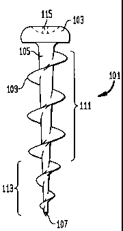
Figs. lA, 1B, and 1C are, respectively, top, side, and bottom views of the
screw.

Figs. 2A and 2B are idealized cross sectional views of a conventional

screw and the instant screw, respectively, in drywall and the holes made by
each
when removed.

DETAILED DESCRIPTION OF SPECIFIC EMBODIMENTS.

With reference to Fig. 1B is seen an idealized side view of the novel screw
101 having a head 103 from which depends a shank 105 that tapers to the tip
107,
the taper being largest at the head and becoming smaller towards the tip.
Disposed on the shank is a helical thread 109 having the geometry of an auger.
For the main portion of the thread 111 the pitch diameter is constant, like a
machine screw. For the bottom portion of the thread 113, the pitch diameter

tapers like a wood screw. Fig. lA is a top view showing the head 103 and a
cavity 115 adapted for receiving a Phillips-type screw driver, although it
should
be understood that any type of driver cavity is suitable. Fig. 1 C is a bottom
view.

The advantage of this novel screw is that the thread is much wider tha.n the
shank, thereby providing a large surface area for cutting into diywall. The
large
tlu=ead (compared with the shank diameter) provides significant pull-out

resistance and holding power. It is preferred that the pitch diameter be at
least
about twice the shank (minor) diameter at the shank's widest point. Because
the
shank is tapered, the pitch diameter in the main portion becomes about four
times
the shank diameter.


CA 02352026 2007-08-02
75361-74

-3-
The reduced diameter shank leaves only a relatively small hole when the
screw is removed.

The bottom portion of the thread had a reduced pitch diameter, although
the pitch is relatively constant. This reduced pitch diameter allows the screw
to
be started easily in drywall, effectively providing a tap.

Fig. 2A shows a cross section of a sheet of drywall 201 in which a
conventional screw 203 has been driven. When the screw is removed it leaves a
hole or bore 205 in which the portions 207 of the drywall engaged by the screw
are seen to be quite small in relation to the bore. In contrast, in Fig. 2B
shows a

similar cross section of a sheet of drywall 201 in which the instant auger
screw
209 has been driven. When the novel screw is removed, the bore 211 revealed is
relatively smaller and thus more cosmetically appealing for repair. Also, the
portions 213 of the drywall engaged by the auger are relatively larger than.
those
left by the conventional screw. It can also be seen that the portions 213
engage

more surface area than those of the conventional screw, thus providing
improved
holding.

In addition, the comparison of Figs. 2A and 2B shows why the present
invention is an improvement over existing screws. The holding power of the
screw is related to the amount of substrate material held between each turn of
the

thread, the number of threads, and the intrinsic strength of the substrate
material.
Gypsum drywall, because of its frangible nature, requires a relatively large
thickness to be strong (a drywall screw is useful only in holding the drywall
to
another substrate). The relatively fine threads of a typical screw (Fig. 2A)
do not
allow for a sufficient amount of material therebetween, especially because the

drywall substrate is a rather frangible material. On the other hand, the
present
screw holds relatively large amount of material between one pitch revolution;
as
shown in Fig. 2B, about one-half of the thickness of the wall is held between
a
single turn of the thread.


CA 02352026 2001-07-03

-4-
This screw essentially slices into the wall and has a relatively small shank
diameter compared with the major diameter. Thus, less of the drywall is
destroyed when the screw is driven, and so when the screw is removed there is
a
much smaller hole to repair than with a conventional screw. The ratio of the

major to minor diameters, and independently thereof the ratio of the major
diameter to the pitch, is preferably at least about 1.5:1, more preferably at
least
about 1.75:1, and most preferably about 2:1 or more. In the screw shown in
Fig.
1B, exemplary dimensions are 0.33 inch for the major diameter and for the
pitch,
and 0.14 inch for the minor diameter; at the bottom portion where the shank is

tapered, the diameter of the tip is about 0.04 inch.

While the novel screw has been shown with a Philips-type head, the head
can have a structure adapted to engage a flat head screw driver or a hex or
square
driver, or the head can be a hex head like a bolt, especially for hanging
shelving
and the like which are relatively heavy objects. Also, the head can be
replaced

with a hook or similar device to function as a picture hanger. Also, while a
single
auger is shown, a double auger thread can be used.

The instant auger screw is preferably made of metal, but could be made
from a hard plastic as well.

The foregoing description is meant to be illustrative and not limiting.
Various changes, modifications, and additions may become apparent to the
skilled artisan upon a perusal of this specification, and such are meant to be
within the scope and spirit of the invention as defined by the claims.

Representative Drawing
A single figure which represents the drawing illustrating the invention.
Administrative Status

For a clearer understanding of the status of the application/patent presented on this page, the site Disclaimer , as well as the definitions for Patent , Administrative Status , Maintenance Fee  and Payment History  should be consulted.

Administrative Status

Title Date
Forecasted Issue Date 2008-11-18
(22) Filed 2001-07-03
(41) Open to Public Inspection 2002-02-08
Examination Requested 2004-06-23
(45) Issued 2008-11-18
Deemed Expired 2016-07-04

Abandonment History

There is no abandonment history.

Payment History

Fee Type Anniversary Year Due Date Amount Paid Paid Date
Application Fee $300.00 2001-07-03
Registration of a document - section 124 $100.00 2002-07-02
Maintenance Fee - Application - New Act 2 2003-07-03 $100.00 2003-05-20
Maintenance Fee - Application - New Act 3 2004-07-05 $100.00 2004-06-07
Request for Examination $800.00 2004-06-23
Maintenance Fee - Application - New Act 4 2005-07-04 $100.00 2005-07-04
Maintenance Fee - Application - New Act 5 2006-07-03 $200.00 2006-06-12
Maintenance Fee - Application - New Act 6 2007-07-03 $200.00 2007-06-26
Maintenance Fee - Application - New Act 7 2008-07-03 $200.00 2008-06-04
Final Fee $300.00 2008-09-02
Maintenance Fee - Patent - New Act 8 2009-07-03 $200.00 2009-06-23
Maintenance Fee - Patent - New Act 9 2010-07-05 $400.00 2011-02-04
Maintenance Fee - Patent - New Act 10 2011-07-04 $450.00 2011-10-06
Maintenance Fee - Patent - New Act 11 2012-07-03 $450.00 2013-06-17
Maintenance Fee - Patent - New Act 12 2013-07-03 $250.00 2013-06-17
Maintenance Fee - Patent - New Act 13 2014-07-03 $250.00 2014-06-30
Owners on Record

Note: Records showing the ownership history in alphabetical order.

Current Owners on Record
POWERS PRODUCTS III, L.L.C.
Past Owners on Record
GAUDRON, PAUL
Past Owners that do not appear in the "Owners on Record" listing will appear in other documentation within the application.
Documents

To view selected files, please enter reCAPTCHA code :


To view images, click a link in the Document Description column. To download the documents, select one or more checkboxes in the first column and then click the "Download Selected in PDF format (Zip Archive)" or the "Download Selected as Single PDF" button.

List of published and non-published patent-specific documents on the CPD .

If you have any difficulty accessing content, you can call the Client Service Centre at 1-866-997-1936 or send them an e-mail at CIPO Client Service Centre.


Document
Description 
Date
(yyyy-mm-dd) 
Number of pages   Size of Image (KB) 
Abstract 2001-07-03 1 13
Description 2001-07-03 4 180
Claims 2001-07-03 1 34
Drawings 2001-07-03 2 18
Representative Drawing 2002-01-11 1 2
Representative Drawing 2007-12-06 1 3
Cover Page 2002-02-01 1 26
Description 2007-08-02 6 228
Claims 2007-08-02 2 57
Representative Drawing 2008-10-27 1 4
Cover Page 2008-10-27 1 29
Correspondence 2001-07-27 1 23
Assignment 2001-07-03 2 81
Assignment 2002-07-02 4 169
Assignment 2002-07-25 1 28
Prosecution-Amendment 2004-06-23 1 33
Prosecution-Amendment 2007-02-05 3 80
Prosecution-Amendment 2007-08-02 11 409
Correspondence 2008-09-02 1 37
Fees 2009-06-23 1 35
Fees 2011-10-06 2 92