Sélection de la langue

Search

Sommaire du brevet 2352026 

Énoncé de désistement de responsabilité concernant l'information provenant de tiers

Une partie des informations de ce site Web a été fournie par des sources externes. Le gouvernement du Canada n'assume aucune responsabilité concernant la précision, l'actualité ou la fiabilité des informations fournies par les sources externes. Les utilisateurs qui désirent employer cette information devraient consulter directement la source des informations. Le contenu fourni par les sources externes n'est pas assujetti aux exigences sur les langues officielles, la protection des renseignements personnels et l'accessibilité.

Disponibilité de l'Abrégé et des Revendications

L'apparition de différences dans le texte et l'image des Revendications et de l'Abrégé dépend du moment auquel le document est publié. Les textes des Revendications et de l'Abrégé sont affichés :

  • lorsque la demande peut être examinée par le public;
  • lorsque le brevet est émis (délivrance).
(12) Brevet: (11) CA 2352026
(54) Titre français: VIS EN FORME DE TARIERE POUR CLOISONS SECHES
(54) Titre anglais: AUGER-LIKE DRYWALL SCREW
Statut: Périmé et au-delà du délai pour l’annulation
Données bibliographiques
(51) Classification internationale des brevets (CIB):
  • F16B 35/00 (2006.01)
  • F16B 25/00 (2006.01)
  • F16B 33/02 (2006.01)
(72) Inventeurs :
  • GAUDRON, PAUL (Etats-Unis d'Amérique)
(73) Titulaires :
  • POWERS PRODUCTS III, L.L.C.
(71) Demandeurs :
  • POWERS PRODUCTS III, L.L.C. (Etats-Unis d'Amérique)
(74) Agent: SMART & BIGGAR LP
(74) Co-agent:
(45) Délivré: 2008-11-18
(22) Date de dépôt: 2001-07-03
(41) Mise à la disponibilité du public: 2002-02-08
Requête d'examen: 2004-06-23
Licence disponible: S.O.
Cédé au domaine public: S.O.
(25) Langue des documents déposés: Anglais

Traité de coopération en matière de brevets (PCT): Non

(30) Données de priorité de la demande:
Numéro de la demande Pays / territoire Date
09/634428 (Etats-Unis d'Amérique) 2000-08-08

Abrégés

Abrégé français

La présente invention porte sur une vis dotée d'une tête, d'une tige et d'un filetage hélicoïdal. La tête, en option, est adaptée pour entrer en contact avec un outil d'entraînement. La tige est fixée à la tête et comprend une extrémité distale libre, et elle est effilée pour réduire le diamètre à partir de la tête à l'extrémité distale. Le filetage hélicoïdal a la géométrie d'une tarière avec un diamètre de fonctionnement d'au moins deux fois le diamètre minimal le plus large de la tige.


Abrégé anglais

The present invention relates to a screw having a head, shank, and a helical thread. The head is optionally adapted to be engaged by a driving tool. The shank is attached to the head and has a free distal end, and is tapered to decrease in diameter from the head to the distal end. The helical thread has the geometry of an auger with a pitch diameter of at least twice the largest minimum diameter of the shank.

Revendications

Note : Les revendications sont présentées dans la langue officielle dans laquelle elles ont été soumises.


-5-
CLAIMS:
1. An auger-like screw for use with dry wall,
comprising:
a. a head portion, adapted to be engaged by a
driving tool;
b. a shank portion, having a proximal end and a
free distal end, wherein said proximal end is attached to
said head portion, and said shank portion having a decrease
in diameter from said proximal end to said free distal end;
and
c. a helical thread, with a geometry of an auger,
having an outside diameter to shank diameter ratio of at
least 2 to 1, and wherein said helical thread has a constant
outside diameter for a substantial portion along the length
of said shank.
2. The auger-like screw of claim 1, wherein said
helical thread is spaced at intervals of approximately 0.5
to 1.0 cm.
3. The auger-like screw of claim 2, wherein said
helical thread is spaced at intervals of
approximately 0.8 cm.
4. The auger-like screw of claim 1, wherein said
ratio is approximately 2.5 to 1.
5. A screw for use with dry wall, comprising:
a. a head, adapted to be engaged by a driving
tool;
b. a thin shank with a slight taper, having a
proximal end and a free distal end, wherein said proximal

-6-
end is attached to said head, and said shank having a
decrease in diameter from said proximal end to said free
distal end; and
c. a helical thread, with a geometry of an auger,
having an outside diameter to shank diameter ratio of at
least 2 to 1, and wherein said helical thread has a constant
outside diameter for a substantial portion along the length
of said shank.
6. A screw comprising:
a head, optionally adapted to be engaged by a
driving tool;
a shank attached to the head and having a free
distal end,
the shank being tapered to decrease in diameter
from the head to the distal end; and
a helical thread in the geometry of an auger
having a pitch diameter of at least about twice the largest
minimum diameter of the shank.
7. The screw of clam 6, wherein the thread has a
first portion of constant diameter.
8. The screw of claim 7, wherein the thread has a
second portion associated with the distal end wherein the
pitch diameter lessens.
9. The screw of claim 6, comprised of metal.
10. The screw of claim 6, comprised of plastic.
11. The screw of claim 6, wherein the head is adapted
to be engaged by a screwdriver.

Description

Note : Les descriptions sont présentées dans la langue officielle dans laquelle elles ont été soumises.

CA 02352026 2007-08-02
75361-74
-1-
AUGER-LIKE DRYWALL SCREW
BACKGROUND OF THE INVENTION.
1. Field of the Invention.
This invention relates to a novel screw for use with drywall (gypsum
plasterboard, sheetrock, etc.) for the homeowner in hanging articles
therefrom.
2. The State of the Art.
Screws have existed for many years and are based on the principle of the
inclined plane providing a wedging action to force the head of the screw into
the
substrate. Different screws have been developed for different materials,
principally for wood and sheet metal, but also for drywall. A typical drywall
screw has a body of a constant diameter and a thread designed to cut into both
the
drywall and the fixture to which it is support (often a metal stud).
Homeowners typically hang pictures, shelves, plants, and other devices or
decoration from their interior walls. Devices such as picture hangers
typically
use a nail and a fulcrum device; the nail can easily come out of the wall or
it may
tear through the sheetrock. Larger fastening devices can be unsightly and are
likely oversized for the job at hand, such as hanging a picture.
What is needed is a small screw with the holding power of a larger screw,
which can be removed, and which does not degrade the drywall significantly
when removed.

CA 02352026 2007-08-02
75361-74
-2-
SUMMARY AND OBJECTS OF THE INVENTION.
One object of an embodiment of this invention is
to provide a relatively small screw with improved holding
power for use in drywall. Another object of an embodiment
is to provide such a screw that can be removed easily
without destroying or degrading the drywall.
An aspect of the invention provides a screw having
a tapered shank and a thread having a diameter and a pitch
greater than the minor diameter, and a head adapted for
being driven by a tool. In essence, one can envision this
screw as a corkscrew having a typical screw head.
Another aspect of the invention provides an auger-
like screw for use with dry wall, comprising: a. a head
portion, adapted to be engaged by a driving tool; b. a shank
portion, having a proximal end and a free distal end,
wherein said proximal end is attached to said head portion,
and said shank portion having a decrease in diameter from
said proximal end to said free distal end; and c. a helical
thread, with a geometry of an auger, having an outside
diameter to shank diameter ratio of at least 2 to 1, and
wherein said helical thread has a constant outside diameter
for a substantial portion along the length of said shank.
A further aspect of the invention provides a screw
for use with dry wall, comprising: a. a head, adapted to be
engaged by a driving tool; b. a thin shank with a slight
taper, having a proximal end and a free distal end, wherein
said proximal end is attached to said head, and said shank
having a decrease in diameter from said proximal end to said
free distal end; and c. a helical thread, with a geometry of
an auger, having an outside diameter to shank diameter ratio
of at least 2 to 1, and wherein said helical thread has a

CA 02352026 2007-08-02
75361-74
-2a-
constant outside diameter for a substantial portion along
the length of said shank.
A still further aspect of the invention provides a
screw comprising: a head, optionally adapted to be engaged
by a driving tool; a shank attached to the head and having a
free distal end, the shank being tapered to decrease in
diameter from the head to the distal end; and a helical
thread in the geometry of an auger having a pitch diameter
of at least about twice the largest minimum diameter of the
shank.

CA 02352026 2007-08-02
75361-74
-2b-
BRIEF DESCRIPTION OF THE DRAWINGS
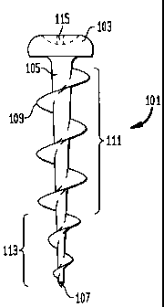
Figs. lA, 1B, and 1C are, respectively, top, side, and bottom views of the
screw.
Figs. 2A and 2B are idealized cross sectional views of a conventional
screw and the instant screw, respectively, in drywall and the holes made by
each
when removed.
DETAILED DESCRIPTION OF SPECIFIC EMBODIMENTS.
With reference to Fig. 1B is seen an idealized side view of the novel screw
101 having a head 103 from which depends a shank 105 that tapers to the tip
107,
the taper being largest at the head and becoming smaller towards the tip.
Disposed on the shank is a helical thread 109 having the geometry of an auger.
For the main portion of the thread 111 the pitch diameter is constant, like a
machine screw. For the bottom portion of the thread 113, the pitch diameter
tapers like a wood screw. Fig. lA is a top view showing the head 103 and a
cavity 115 adapted for receiving a Phillips-type screw driver, although it
should
be understood that any type of driver cavity is suitable. Fig. 1 C is a bottom
view.
The advantage of this novel screw is that the thread is much wider tha.n the
shank, thereby providing a large surface area for cutting into diywall. The
large
tlu=ead (compared with the shank diameter) provides significant pull-out
resistance and holding power. It is preferred that the pitch diameter be at
least
about twice the shank (minor) diameter at the shank's widest point. Because
the
shank is tapered, the pitch diameter in the main portion becomes about four
times
the shank diameter.

CA 02352026 2007-08-02
75361-74
-3-
The reduced diameter shank leaves only a relatively small hole when the
screw is removed.
The bottom portion of the thread had a reduced pitch diameter, although
the pitch is relatively constant. This reduced pitch diameter allows the screw
to
be started easily in drywall, effectively providing a tap.
Fig. 2A shows a cross section of a sheet of drywall 201 in which a
conventional screw 203 has been driven. When the screw is removed it leaves a
hole or bore 205 in which the portions 207 of the drywall engaged by the screw
are seen to be quite small in relation to the bore. In contrast, in Fig. 2B
shows a
similar cross section of a sheet of drywall 201 in which the instant auger
screw
209 has been driven. When the novel screw is removed, the bore 211 revealed is
relatively smaller and thus more cosmetically appealing for repair. Also, the
portions 213 of the drywall engaged by the auger are relatively larger than.
those
left by the conventional screw. It can also be seen that the portions 213
engage
more surface area than those of the conventional screw, thus providing
improved
holding.
In addition, the comparison of Figs. 2A and 2B shows why the present
invention is an improvement over existing screws. The holding power of the
screw is related to the amount of substrate material held between each turn of
the
thread, the number of threads, and the intrinsic strength of the substrate
material.
Gypsum drywall, because of its frangible nature, requires a relatively large
thickness to be strong (a drywall screw is useful only in holding the drywall
to
another substrate). The relatively fine threads of a typical screw (Fig. 2A)
do not
allow for a sufficient amount of material therebetween, especially because the
drywall substrate is a rather frangible material. On the other hand, the
present
screw holds relatively large amount of material between one pitch revolution;
as
shown in Fig. 2B, about one-half of the thickness of the wall is held between
a
single turn of the thread.

CA 02352026 2001-07-03
-4-
This screw essentially slices into the wall and has a relatively small shank
diameter compared with the major diameter. Thus, less of the drywall is
destroyed when the screw is driven, and so when the screw is removed there is
a
much smaller hole to repair than with a conventional screw. The ratio of the
major to minor diameters, and independently thereof the ratio of the major
diameter to the pitch, is preferably at least about 1.5:1, more preferably at
least
about 1.75:1, and most preferably about 2:1 or more. In the screw shown in
Fig.
1B, exemplary dimensions are 0.33 inch for the major diameter and for the
pitch,
and 0.14 inch for the minor diameter; at the bottom portion where the shank is
tapered, the diameter of the tip is about 0.04 inch.
While the novel screw has been shown with a Philips-type head, the head
can have a structure adapted to engage a flat head screw driver or a hex or
square
driver, or the head can be a hex head like a bolt, especially for hanging
shelving
and the like which are relatively heavy objects. Also, the head can be
replaced
with a hook or similar device to function as a picture hanger. Also, while a
single
auger is shown, a double auger thread can be used.
The instant auger screw is preferably made of metal, but could be made
from a hard plastic as well.
The foregoing description is meant to be illustrative and not limiting.
Various changes, modifications, and additions may become apparent to the
skilled artisan upon a perusal of this specification, and such are meant to be
within the scope and spirit of the invention as defined by the claims.

Dessin représentatif
Une figure unique qui représente un dessin illustrant l'invention.
États administratifs

2024-08-01 : Dans le cadre de la transition vers les Brevets de nouvelle génération (BNG), la base de données sur les brevets canadiens (BDBC) contient désormais un Historique d'événement plus détaillé, qui reproduit le Journal des événements de notre nouvelle solution interne.

Veuillez noter que les événements débutant par « Inactive : » se réfèrent à des événements qui ne sont plus utilisés dans notre nouvelle solution interne.

Pour une meilleure compréhension de l'état de la demande ou brevet qui figure sur cette page, la rubrique Mise en garde , et les descriptions de Brevet , Historique d'événement , Taxes périodiques et Historique des paiements devraient être consultées.

Historique d'événement

Description Date
Le délai pour l'annulation est expiré 2016-07-04
Lettre envoyée 2015-07-03
Inactive : TME en retard traitée 2013-06-17
Lettre envoyée 2012-07-03
Inactive : TME en retard traitée 2011-10-06
Lettre envoyée 2011-07-04
Inactive : TME en retard traitée 2011-02-04
Lettre envoyée 2010-07-05
Accordé par délivrance 2008-11-18
Inactive : Page couverture publiée 2008-11-17
Préoctroi 2008-09-02
Inactive : Taxe finale reçue 2008-09-02
Un avis d'acceptation est envoyé 2008-03-18
Lettre envoyée 2008-03-18
Un avis d'acceptation est envoyé 2008-03-18
Inactive : Approuvée aux fins d'acceptation (AFA) 2007-11-30
Modification reçue - modification volontaire 2007-08-02
Inactive : Dem. de l'examinateur par.30(2) Règles 2007-02-05
Inactive : CIB de MCD 2006-03-12
Lettre envoyée 2004-07-06
Requête d'examen reçue 2004-06-23
Exigences pour une requête d'examen - jugée conforme 2004-06-23
Toutes les exigences pour l'examen - jugée conforme 2004-06-23
Lettre envoyée 2002-08-21
Inactive : Correspondance - Transfert 2002-07-25
Inactive : Transfert individuel 2002-07-02
Demande publiée (accessible au public) 2002-02-08
Inactive : Page couverture publiée 2002-02-07
Inactive : CIB en 1re position 2001-08-23
Inactive : Lettre de courtoisie - Preuve 2001-07-31
Inactive : Certificat de dépôt - Sans RE (Anglais) 2001-07-27
Exigences de dépôt - jugé conforme 2001-07-27
Demande reçue - nationale ordinaire 2001-07-27

Historique d'abandonnement

Il n'y a pas d'historique d'abandonnement

Taxes périodiques

Le dernier paiement a été reçu le 2008-06-04

Avis : Si le paiement en totalité n'a pas été reçu au plus tard à la date indiquée, une taxe supplémentaire peut être imposée, soit une des taxes suivantes :

  • taxe de rétablissement ;
  • taxe pour paiement en souffrance ; ou
  • taxe additionnelle pour le renversement d'une péremption réputée.

Veuillez vous référer à la page web des taxes sur les brevets de l'OPIC pour voir tous les montants actuels des taxes.

Titulaires au dossier

Les titulaires actuels et antérieures au dossier sont affichés en ordre alphabétique.

Titulaires actuels au dossier
POWERS PRODUCTS III, L.L.C.
Titulaires antérieures au dossier
PAUL GAUDRON
Les propriétaires antérieurs qui ne figurent pas dans la liste des « Propriétaires au dossier » apparaîtront dans d'autres documents au dossier.
Documents

Pour visionner les fichiers sélectionnés, entrer le code reCAPTCHA :


Pour visualiser une image, cliquer sur un lien dans la colonne description du document. Pour télécharger l'image (les images), cliquer l'une ou plusieurs cases à cocher dans la première colonne et ensuite cliquer sur le bouton "Télécharger sélection en format PDF (archive Zip)" ou le bouton "Télécharger sélection (en un fichier PDF fusionné)".

Liste des documents de brevet publiés et non publiés sur la BDBC .

Si vous avez des difficultés à accéder au contenu, veuillez communiquer avec le Centre de services à la clientèle au 1-866-997-1936, ou envoyer un courriel au Centre de service à la clientèle de l'OPIC.


Description du
Document 
Date
(aaaa-mm-jj) 
Nombre de pages   Taille de l'image (Ko) 
Dessin représentatif 2002-01-11 1 2
Page couverture 2002-02-01 1 26
Description 2001-07-03 4 180
Revendications 2001-07-03 1 34
Abrégé 2001-07-03 1 13
Dessins 2001-07-03 2 18
Description 2007-08-02 6 228
Revendications 2007-08-02 2 57
Dessin représentatif 2007-12-06 1 3
Dessin représentatif 2008-10-27 1 4
Page couverture 2008-10-27 1 29
Certificat de dépôt (anglais) 2001-07-27 1 163
Demande de preuve ou de transfert manquant 2002-07-04 1 109
Courtoisie - Certificat d'enregistrement (document(s) connexe(s)) 2002-08-21 1 112
Rappel de taxe de maintien due 2003-03-04 1 106
Accusé de réception de la requête d'examen 2004-07-06 1 177
Avis du commissaire - Demande jugée acceptable 2008-03-18 1 164
Avis concernant la taxe de maintien 2010-08-16 1 170
Quittance d'un paiement en retard 2011-02-17 1 164
Avis concernant la taxe de maintien 2011-08-15 1 170
Quittance d'un paiement en retard 2011-10-17 1 163
Avis concernant la taxe de maintien 2012-08-14 1 170
Quittance d'un paiement en retard 2013-06-17 1 163
Avis concernant la taxe de maintien 2015-08-14 1 171
Correspondance 2001-07-27 1 23
Correspondance 2008-09-02 1 37
Taxes 2009-06-23 1 35
Taxes 2011-10-06 2 92